IEEE ISIE 2006, July 9-12, 2006, Montreal, Quebec, Canada. Induction Motor Fault Detection by using Wavelet decomposition on dqO components. Cusido J.
IEEE ISIE 2006, July 9-12, 2006, Montreal, Quebec, Canada
Induction Motor Fault Detection by using Wavelet decomposition on dqO components Cusido J., Rosero J.A., Ortega J.A., Garcia A., L. Romeral Dept. d'Enginyeria Electr6nica. Universitat Politecnica de Catalunya. C. Colom 1. 08222 Terrassa. Catalunya. Spain, e-mail: romeralaeel.upc.es Abstract: Early detection of interturn shorts during motor operation would eliminate consequential damage to adjacent coils and the stator core, then reducing repair costs and motor outage time. In addition to the benefits gained from early detection of turn insulation breakdown, significant advantages would accrue by locating the faulted coil within the stator winding. Fault location would not only increase the speed of the repair, but would also permit more optimal scheduling of the repair outage. Motor Current Signature Analysis (MCSA) method is widely used as a diagnose tool for industrial applications. On the other hand, Park's transform is the most popular transformation used in vector control algorithms. By analyzing the current spectra of dqO Park components with MCSA method it is possible to improve earlier fault detection. Moreover, using Wavelet transform as signal analysis method it is possible to reduce signal noise effects. Experimental results clearly corroborate the main aim of the paper. Keywords - Electrical drives, Induction motor, Fault detection, Inter turns shorts, dqO transform, Wavelet analysis.
I INTRODUCTION Induction Motor is the most widely used electrical machine that allows converts electrical power to mechanical power. It has become more popular since the appearance of motor control systems. Nowadays the 70% of the industrial applications uses induction machines, and they consume more than 50% of an industrialized nation's total generating
capability.
A great number of these motors are powered by inverters and used in different control applications Vector Control is probably the most popular high performance motor control applications. Since latest seventies, Vector Control Theory has been introduced. Nowadays vector control is a standard industrial solution [1], used in a wide range of machines, robots, and even power systems. In critical applications where a fault could become a serious trouble, not only a robust control system is needed, but also a good diagnostic method is required. Different diagnostic methods are introduced in the bibliography. Among them, MCSA is probably the most widely used, nowadays considered as industrial standard to fault detection in an early state [2] [3]. MCSA focuses its efforts on the spectral analysis of the stator current and has been successfully used to detect mechanical faults [4], such as broken rotor bars, bearing damage and dynamic eccentricity, or electrical faults [5], such as single or multiple phase short circuits, open phase and abnormal connections.
1-4244-0497-5/06/$20.00 C 2006 IEEE
In case of low power machines, the amplitude of the fault harmonic is too small in the incipient fault stage, and the relationship signal to noise is very low, and thus the failure becomes difficult to identify. On the other hand, the signal processing needed by a MCSA method, such as the FFT (Fast Fourier Transform), is difficult to apply in high power induction machines because the slip frequency is very low, the sideband harmonics are close to the fundamental one and the frequency resolution must be high. The problem of frequency accuracy is very tricky in both cases, with low torque operation and very small slip, and at low speed of the machine, because the fault frequency separation from the fundamental harmonic depends directly on the slip and speed. Moreover, medium and large power motors working in fluid control applications like air conditioners and water control often operate at medium power or even less, which implies very slow slip frequencies, and hence quite close harmonics in the side band spectrum, hindering the task of localizing and identifying fault harmonics. Different new techniques have been developed and introduced in order to palliate such problems. Wavelet analysis [6] is applied to view frequency harmonics variation during time. PSD (Power Spectral Density) [7] has been another well know signal technique applied for this purpose. This paper proposes to improve the MCSA method by analyzing dqO components obtained from Park transformation instead of abc stator currents. A better harmonic's amplitude relationship between healthy and faulty motors is shown by using Park's Transform, which combined with Wavelet transformation allows optimizing the fault detection.
II MOTOR'S HARMONICS
a) Teeth wave harmonics The harmonic order is directly related with the slot number per 2 times the polar step, and its magnitude depends on the distribution winding factor. Every stator harmonic creates synchronous torques and requires special attention on the teeth wave. These kinds of harmonics are in the order
2406
fs,ot=f
(1)
n+1
p
where n is an integer, Z1 is the stator slots number, and p is the number of pairs of poles. b) Asynchronous Parasitic Torques + fil v from main The stator v harmonic turns at fi frequency fi and the harmonic slip could be expressed as
fi=
s
r
+(
s)v
(2)
where sv is the harmonic's v slip and fr is the rotor frequency. The induced rotor current frequency for the v harmonic flux is determined by
f2v
=
fi[l +(l -41
produced by a set of two orthogonal windings, each of them sinusoidally - distributed with 7I(3/2 Ns) turns: one winding along the d-axis, and the other along the q-axis. Park's transform is a mathematical tool that allows
simplifying induction motor model equations. It is based in
an arithmetical base rotation that is able to convert a symmetrical system with three variables (a, b, c) to another with only two orthogonal variables (d, q). Usually, these two variables are referred in ac motor control to a flux and torque. If asymmetries exist and are considered, a third variable (0) appears which is usually referred to the common mode. Park's transform is detailed on the following equations (5, 6). x0
Xd
(3)
Xq)
c) Synchronous Harmonics Synchronous harmonics appear for mutual action between stator and rotor harmonics of the same order. It means v=k considering the rotor speed, i.e., they turn in synchronism. The stator harmonics fsiot=fs(6 A-±1) should be specially took into account for these compositions. Synchronous harmonics are
v
2 =
sin
where Z2 are either rotor bars or rotor slots. II PROPOSED APPROACH By analyzing stator current harmonic spectra, incipient state of shorted turns could be detected, especially as abnormalities on teeth wave, and parasitic synchronous and asynchronous harmonics. However, most of those harmonics have low amplitude, not enough for good detection and correct diagnosis of the fault.
Park's transform is the most widely used transformation for flux and torque control in Vector Control applications. Then it is proposed to use this transformation for analyzing stator current harmonics, especially those of less amplitude. A. Park Transformation to dqO space Variables d, q, o, are obtained from a, b, c stator currents using Park's transform matrix. It could be used not only for currents, also for voltages or flux even with the matrix
inverse. Current components dqO, are obtained from abc stator currents using Park's transformation matrix, which could be used not only for currents, but also for voltages or fluxes. For dynamic analysis and control of ac machines, two orthogonal equivalent windings are needed, such as the torque and the flux within the machine could be controlled independently. At any instant of time, the air gap mmf distribution caused by the three phase windings can also be
(0)
3
2X)
2
-sin
3~
2os /o
CO
3 )
(5)
Co
-sin (O)
cos(O) r2
I
Xb >/ 3 () 1x ( 3 ) -sin (jO ±2+ 3 )X 0
Co
1,~
I
(4)
I
cos(o)
3 \1
expressed as
+ k vZ- kZ22 =+2p +1; += p P~~~~~~~ p
I 2
T
(6)
3ll
sin
jo±2
/-
q
Where transformed variables can be voltages, currents or fluxes, K, is the Park's transform, and 0 is the motor turn's angle that is chosen as a reference angle. As it is later demonstrated, Park's transformed variables are adequate for fault detection because stator current fault harmonics grow up in amplitude, and proper detection is easier even in incipient fault condition. However the relationship between fault harmonics and signal noise is still the most important trouble for the detection, even after Park's transformation. Wavelet analysis is capable not only of revealing aspects of data that other signal analysis techniques miss, like trends, breakdown points and discontinuities in higher derivatives, but also is capable to centre its study in a specific bands missing noise effects. B. Wavelet Transform
Fourier analysis consists of breaking up a signal into sine waves of various frequencies. Similarly, wavelet analysis is the breaking up of a signal into shifted and scaled versions of
the original (or mother) wavelet. Wavelet analysis [8] [9] is capable of revealing hidden aspects of data, like discontinuities and self-similarities. Also it allows choosing frequency bands and denoising signal by using proper mother wavelet functions. The scaling function wavelet could be considered as a digital filter (DFI) that allows denoising signal and focusing the spectral analysis in the required band. A discrete signal x[n] could be decomposed as
2407
J-1
x[n] = Za k
kj0o k [n]+
Z Z j=jo k
III EXPERIMENTAL RESULTS
(7)
dj,k j,k[n]
where o[n] is the scaling function that could be defined as an aggregation for wavelets at scales larger than one.
qp[n]
k [n]= 2102 X(2jo n-k) is the scaling function at scale s = 2'° shifted by k, is the mother wavelet,
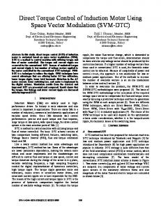
(p,', [n] = 22 (2 j n-k) is the mother wavelet at scale s= 2 shifted by k, ajOk are the coefficients of approximation at scale s = 210 da k are the coefficients of detail at scale s = 2', and N=2Jj, being N the number of samples of x[n]. In other words, a discrete signal could be constructed by means of a sum of a J-jo details plus one approximation of the signal at scale s = 2jo . For the implementation of DWT, a filter band structure is often used. Fig. 1 shows the decomposition or analysis filter bank for obtaining the forward DWT coefficients. The approximation coefficients at lower level are passed through a high pass and a low pass filter followed by a downsampling by two to compute both the detail (from the highpass filter) and the approximation (from the low-pass filter) coefficients at a higher level. The two filters are related to each other and they are known as quadrature mirror filters. By this way, the details and the approximations at different scales could be obtained by means of a tree decomposition showed in Fig. 1.
Several tests have been done with 1.1 kW induction motors, with star grid supply at 380V, 50 Hz. The motor has 2 pair of poles and its nominal speed is about 1410 rpm. Healthy and faulty motors have been used in the experiments, always working at nominal load torque. The damaged induction motor has about eight short-circuited turns in one phase. A. Fourier Analyses of Motor Stator Currents
Fig. 2 and Fig. 3 show stator currents for healthy and faulty motors, and Fig. 4 shows the current spectra for both kinds of motors as well. First of all, a current diminution and unbalancement is appreciated on shorted-turned machine, as well in the temporal stator current distribution as on the spectral analysis. Moreover, harmonics 25, 75, 100, 350Hz present the same amplitude for faulty and healthy motor, which is due to that these harmonics appear for misalignments and they exist even in a healthy machine. In harmonics located at 125 Hz, 150 Hz and 175Hz, the increase of amplitude is significant, up to five times for faulty machine. However, two of these harmonics, those at frequencies of 125 Hz and 175 Hz, appear also for healthy machines, due to standard misalignments and rotor eccentricity faults. The third harmonic at 150 Hz can also appear in case of supply misalignment in phases, and denotes electrical problems. Therefore, an exhaustive study is needed for differentiating the kind of failure in the motor. 2
A LApprox.
Level 3
0
Detail Level 3
f5/16
Detail Level 2
f5/8
Detail Level 1
fs/4
310
fs/2
Fig. 1 Frequency ranges for details and final approximation
-2 \0
Frequency Bands (Hz) 2500 1250 1250 675 675 337.5 337.5 168.25 168.25 84.37 42.2 84.37 42.2
V J
0.02
0.03
\J
V
0.04
y \
0.05
Time (S)
\
0.06
J
0.07
\V
0.08
\JV
0.09