Internet-based Design Visualization for Layered Manufacturing
Recommend Documents
An adaptive slicing algorithm that can vary the layer thickness in relation to local geometry ...... for Layered Manufacturing Techniques", Computer Aided Design, ...
A slicer for generating two-dimensional contours. The architecture of the proposed slicing engine is shown in the block diagram in Figure 4. Arrows show the.
Jan 12, 2007 - This thesis is presented in partial fulfilment for the degree of. DOCTOR ...... However, web graphic designers can reduce omissions ...... Freehand 10, and images decorating the form were retouched by Adobe Photoshop. 6.0.
the concurrent design of material composition and shape of components, and a new ... problem involving material distribution. ... The optimization problem.
A designer's fabrication notes are a collection of notes that accompany PCB data
.... Manufacturing notes specific to only the manufacturing process and not the.
manufacture of nanometer regime VLSI designs. New EDA ... manufacturing-aware design â one that affects the design flow fundamentally and also adds much ...Missing:
Design for Manufacturing (DFM) and design for assembly (DFA) are the
integration of product design and process planning into one common activity. The
goal is ...
experimentally observed value for pure-resin mold-fabricated specimens. Table 1. Material data for reinforcing fibers (Owens Corning 737BD milled glass fiber).
order to share skills, using the virtual enterprise concept. ... automobile industry), which requires the job shop type of ... the network is an intelligent agent [4].
Since FILi carries direction,. FIL also carries a direction, noted as dir(FIL ), which is either the same as Zi or the opposite of Zi Fig. 14b . c. Select any point Va in ...
adaptive slicing to control/select layer thickness based on user ... Proceedings of the ASME 2014 International Design Engineering Technical Conferences &.
turing systems based on agent systems and discusses relevant capabilities of the semantic agents ..... tem support, process modeling and task scheduling (see Fig. 1), applying this ap- .... receives an exception ticket to avert the danger. ... ductio
Practitioner's Handbook for User Interface Design. Deborah J. Mayhew.
Contextual Design: Defining Customer-Centered. Systems. Hugh Beyer and
Karen ...
Benefits of DFM. – SIMPLIFY the design of product. – Reduce the number of parts
, and the cost of parts. – Reduce the time of manufacturing and assembly.
Design for Manufacturing. Teaching materials to accompany: Product Design and
Development. Chapter 11. Karl T. Ulrich and Steven D. Eppinger. 2nd Edition ...
which aims to explain why the SEI is very thick and how the multi-layered structure is formed ... by the features of the solid electrolyte interphase (SEI) grown on.
We describe the design and implementation of a coherent sweep plane slicer, built on top of a topological data structure, which. âslicesâ a tessellated 3-D CAD ...
modeling and design of bone structures and reverse engineering for CAD-based ... degrade at a rate similar to the growth of new tissue cells. ... enabling technological developments in computer-aided design, in medical image processing,.
We describe the design and implementation of a coherent sweep plane slicer, built on top of a topological data structure, which. âslicesâ a tessellated 3-D CAD ...
Jan 31, 2014 - HAL Id: hal-00940085 https://hal.archives-ouvertes.fr/hal-00940085. Submitted on ...... Ashby MF, Brechet Y, Cebon D, Salvo L (2004) Selection.
additive fabrication of an antenna support arm for space satellite performed by OptiStruct and Altair Product Design teams at Altair Engineering showed a weight ...
layouts are made possible using the prefuse visualization toolkit Layout class
which provides many different visualization layouts and is easily extensible to ...
problems can be solved with better visualization support, e.g. issues concerning workshop-layout, ... using point cloud models for visualization support when.
Following is a compilation of design & manufacturing knowledge you should
accrue in this class. You should ... material and the raw stock size in the
drawing's general notes. For example ..... 2. http://www.unm.edu/~bgreen/ME101/
dfm.pdf ...
Internet-based Design Visualization for Layered Manufacturing
It directly provides designers with an advanced preprocessor functionality, design visualization/optimization, as well as model display, repair, and slicing over ...
Concurrent Engineering http://cer.sagepub.com
Internet-Based Design Visualization for Layered Manufacturing Haeseong J. Jee and R. Ian Campbell Concurrent Engineering 2003; 11; 151 DOI: 10.1177/1063293X03035389 The online version of this article can be found at: http://cer.sagepub.com/cgi/content/abstract/11/2/151
Published by: http://www.sagepublications.com
Additional services and information for Concurrent Engineering can be found at: Email Alerts: http://cer.sagepub.com/cgi/alerts Subscriptions: http://cer.sagepub.com/subscriptions Reprints: http://www.sagepub.com/journalsReprints.nav Permissions: http://www.sagepub.com/journalsPermissions.nav
CONCURRENT ENGINEERING: Research and Applications Internet-based Design Visualization for Layered Manufacturing Haeseong J. Jee1,* and R. Ian Campbell2 1
Department of Mechanical Engineering, Hong-Ik University, 72-1 Sang-Su-Dong, Mapo-Ku, Seoul 121-791, Korea 2
Department of Design and Technology, Loughborough University, Loughborough, Leicestershire LE11 3TU, UK
Abstract: When considering the use of layered manufacturing (LM), there are many issues a designer has to address for handling a stereolithography tessellation language (STL) model, the de facto standard for LM. In this paper, we propose an Internet-based design visualization tool for decision support when optimizing the LM process in support of a highly interactive and collaborative virtual environment between CAD designers and LM processes over networks. It directly provides designers with an advanced preprocessor functionality, design visualization/optimization, as well as model display, repair, and slicing over the network. This can help smooth data transfer from CAD to the LM process with minimum inconsistency in CAD data. Key Words: CAD, LM, internet, design visualization, STL.
1. Introduction Layered manufacturing (LM) technologies have an ability of creating a physical part directly from its computer model by adding materials on a layer by layer basis. Major application areas have been early verification of product designs and quick production of prototypes for testing. Once a computer model is generated for a physical object, it needs to be communicated to another computer system or LM machines for further processing. CAD model data is now frequently transmitted to various LM processes using STL. Sometimes, however, CAD systems generate STL files with geometric flaws. In fact, STL has drawbacks such as redundancy, inaccuracy, and lack of integrity. Most software efforts in the emerging LM community have thus focused on geometrical verification of STL CAD models prior to part fabrication [1–3], and there are now several very good software products available that will find and fix flaws in STL files [4]. Over the years, however, as more and more companies have switched to solid-modeling CAD software systems that almost always produce good STL files, STL fixing has become less of a concern for most designers. Nowadays, service bureaus that offer users the opportunity to try out new technologies and test their products are beginning to appear in large numbers,
*Author to whom correspondence should be addressed. E-mail: [email protected]
and people want to do a lot more with STL files and LM than simply make three-dimensional prints of their CAD files. For example, designers themselves want to use visualization [5] and optimization [6,7] as well as repair of the STL file in order to avoid as much physical prototyping as possible since it is expensive to go through a full manufacturing and assembly prototyping cycle. Emerging LM industry has thus created a need for preprocessor software that enables designers to conduct design-oriented works such as visualization/optimization as well as do repair/conversion of an STL file into data recognized by the actual LM machine [8]. However, there are still many issues a designer has to address for handling an STL model and, moreover, most recent LM processes possess quite different capabilities, and most are not even isotropic. In the mean time, rapid advances in computing and communication technologies are creating a new approach for product design and manufacturing. Recently researchers and developers have moved toward creating manufacturing environments for automated LM capability on the network [9,10] and a number of companies have been working to establish the LM marketplace on the Internet in order to save a purchaser time by enabling him/her to submit requests for quotation to multiple service providers simultaneously. There is no doubt that the Internet will change the way LM services are delivered. Today designers can just skip all those irritating issues by visiting a webbased service bureau and leaving all to companies that readily supply LM services rather than set up and operate their own equipment. Orders are now taken for
LM parts through service providers’ web pages; what designers are supposed to do is to upload their STL files to the company server in electronic form through the Internet either by direct upload, ftp file transfer, or as an e-mail attachment although many CAD models are still transferred through hand-carried tapes. Nevertheless, this does not fundamentally change the buying process itself, and it still requires a lot of back and forth communication between the service purchaser and the provider. Therefore, in many cases, designers still need to be playing an important part in the preprocess works even being together with web-based service providers, which, after all, requires highly interactive preprocess tools in support of the designer exchanging design decisions directly with service providers over the network. In this paper, we propose an Internet-based design visualization tool for decision support when optimizing the LM process in support of a highly interactive and collaborative virtual environment between CAD designers and LM processes over the network. Figure 1 shows two different process configurations for making interface between CAD designers and LM processes;
R. I. CAMPBELL
the upper one is for the traditional configuration and the lower one for the new configuration. Compared to the traditional configuration that relies upon quotations through network connection only, the new configuration is additionally supported by an Internet based preprocessor that can be realized by developing a client/ server model on the network. The Internet based preprocessor allows the client to fully access and utilize preprocessor functionality such as model display, slicing, and visual simulation of the design in cooperation with the service providers over the network. Hence the new process environment is expected to fill the gap between CAD designers and various LM processes and, moreover, to help smooth data transfer from CAD to LM process over the network.
2. System Configuration and Functionality The configuration of the proposed system consists of three main parts; server, client, and the Internet in between as shown in Figure 2. In this client/server model the server end mainly manages the network connection with clients and continually listens on one end of the channel. On the contrary the client program periodically connects with the server to exchange data. The server has a database of STL files to be utilized by any client for file testing and processing. In other words the server manages a database for handling STL files and a client can access the server in order to search appropriate STL files. The client can also directly upload and register his own STL files to the server for preprocessing work. 2.1 Interactive Functionality Based on the Internet
Figure 3. Three different types of image display of a CAD model; original CAD model (left), accumulated sliced layers wire framed (center), and visually simulated layer stack model with a single color-shading (right).
Figure 4. A computer image displaying a surface roughness with differently shaded colors based on the slanted angle of STL facets.
Figure 5. An illustration of estimating staircase cusp size between two adjacent layers.
(based on the average staircase cusp size on each layer stack). Since, however, surface quality is considered as a local property, we expect that the color coding based on the maximum staircase cusp size on each layer stack will be preferred by most designers, rather than the one based on the average size (another color coding example based on the maximum staircase cusp size will be shown later as a case study example). Though this method still does not provide a direct indicator of surface roughness it can be used as a quick test to see whether the designer should adjust the part orientation, then recreate the visualized model that has better surface quality for the LM part, or not over the Internet. An automated decision-making procedure for determining a proper part orientation can be alternatively conducted using a simple optimization algorithm with iterative slicing as shown in Figure 6(b). This would be particularly valuable if variable thickness layers were available. The color-coding could be used to decide which layers require to be sliced with a thinner value.
decision support; a computer image displaying smooth, shaded object of an STL file, spider (a), two different computer images displaying a visually simulated layer stack model of the LM part in different scales on the Internet (b and c), and a computer image displaying the
Figure 6. Two different visualizations for the decision support: (a) Various staircase cusp sizes with differently shaded colors on the layer stack model; (b) An automated decision-making procedure for determining a proper part orientation.
R. I. CAMPBELL
various staircase cusp sizes with differently shaded colors on the same layer stack model (d – based on the maximum staircase cusp size on each layer stack). If the resulting image looks acceptable, the user can assign a working order for LM fabrication to the server. The server can then search an appropriate LM service bureau for the assigned order and pass the order information to the relevant bureau in order to execute the fabrication. Working orders, when using remote search and evaluation (RSE) tool, could be assigned directly to a specific service bureau depending on users’ choices. Using the RSE functionality on the Internet, users’ attention can quickly be switched to a specific LM service bureau in which they might be interested. In this paradigm of future client/server model, however, it is supposed that all LM service bureaus under consideration are bound by an agreement to have an Applet for publication of the manufacturing capabilities of their own processing LM machines on the Internet. Once the information concerning all of the LM processes are acquired, RSE can formulate a set of rules to evaluate the processes and select the most appropriate one based on the submitted requirements.
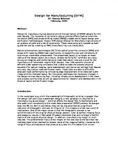
Figure 7. The server manager controlling the network connection with clients.
Internet without ironclad protection of their designs against all hazards, and they may still need venders’ own developing preprocessor software in order to execute some design-intensive works such as generation of complex internal build patterns/support structures and determination of optimum layer thickness of the LM part. It is expected that the method can construct a tentative collaborative environment on the Internet for automated LM capability and help smooth CAD data transfer with minimum inconsistency from CAD to LM process, which enables designers to be able to generate physical prototypes through a cheaper and betteramortized process.
5. Jee, H. and Sachs, E. (2000). A Visual Simulation Technique for 3D Printing, Advances in Engineering Software, 31(2): 97–106. 6. Lan, P.T., Chou, S.Y., Chen, L.L. and Gemmill, D. (1997). Determining Fabrication Orientation for Rapid Prototyping with Stereolithography Apparatus, Computer-Aided Design, 29(1): 53–62. 7. Alexander, P., Allen, S. and Dutta, D. (1998). Part Orientation and Build Cost Determination in Layered Manufacturing, Computer-Aided Design, 30(5): 343–356. 8. Barequet, G. and Kaplan, Y. (1998). A Data Front-End for Layered Manufacturing, Computer-Aided Design, 30(4): 231–243. 9. Bailey, J.M. (1995). Tele-Manufacturing: Rapid Prototyping on the Internet, IEEE Computer Graphics & Applications, 15(6): 20–26. 10. Luo, C.R. et. al. (1999). Tele-Control of Rapid Prototyping Machine Via Internet for Automated TeleManufacturing, IEEE International Conference on Robotics and Automation, 3: 2203–2208. 11. Dolenc, A. and Ma¨kela¨, I. (1994). Slicing Procedure for Layered Manufacturing Techniques, Computer-Aided Design, 26(2): 119–126. 12. Kulkarni, P. and Dutta, D. (1996). An Accurate Slicing Procedure for Layered Manufacturing, Computer-Aided Design, 28(9): 683–697. 13. Chandru, V., Manohar, S. and Edmond Prakash, C. (November, 1995). Voxel-Based Modeling for Layered Manufacturing. IEEE Computer Graphics and Applications, 42–47. 14. Jee, H. and Sachs, E. (2000). Surface Macro-Texture Design for 3D Printing, Rapid Prototyping Journal, 6(1): 50–59. 15. Campbell, R.I., Jee, H. and Lee, H. (2000). Visualization Tools for Design Support in SFF, In: Proceedings of the SFF Symposium, Department of Mechanical Engineering, University of Texas at Austin, pp. 437–44.
R. I. CAMPBELL
R. Ian Campbell R. Ian Campbell worked as a design engineer at Ford Motor Company and Rover Cars before moving to academia in 1989. He is currently a Senior Lecturer at Loughborough University in the Department of Design and Technology where he is leader of the Design Research Group. He has had many papers published in international conferences and journals in the areas of engineering design and rapid prototyping. His latest research efforts have been in the area of user-centred design and advanced CAD interfaces. Dr Campbell is editor of the Rapid Prototyping Journal and serves on the programme committees of several international conferences.