ABSTRACT. We consider the area of train control systems like the. European Train Control Systems ETCS where several di erent scenarios are considered and ...
INTEROPERABILITY IN TRAIN CONTROL SYSTEMS0 SPECIFICATION OF SCENARIOS USING OPEN NETS J. Padberg
L. Jansen
Technical University Berlin Institut fur Kommunikation und Softwaretechnik1
R. Heckel
Universit�a degli Studi di Pisa, Dipartimento di Informatika
Technische Universitat Braunschweig Institut fur Regelungs- und Automatisierungstechnik
H. Ehrig
Technische Universitat Berlin Institut fur Kommunikation und Softwaretechnik1 the European Union is the development of a European Train Control System ETCS, which allows e�cient, smooth and secure travel by train across European Countries. In Germany the `Deutsche Bahn AG' (DB) is cooperating with the `Institut fur Regelungs- und Automatisierungstechnik' (IFRA) in Braunschweig in order to enhance the design process for ETCS in a joint ETCS project [JLPS97a]. The main problem is to identify all relevant scenarios within ETCS and to provide a reliable speci cation for all these scenarios separately as well as for the interoperability of the corresponding system components. In the ETCS-project about 50 scenarios have been identi ed and speci ed separately using high-level Petri nets [JLPS97b], but it is still open to model the interoperability based on these scenarios in a satisfactory way. In this paper we study interoperability for a simpli ed version of a railway crossing control system (RCCS). The general version of RCCS has been stated as a reference case study in the German DFG-Schwerpunktprogramm `Integration von Techniken der Softwarespezi kation fur Ingenieurwissenschaftliche Anwendungen' [Ehr97]. The RCCS problem is closely related to the General Railroad Crossing problem stated in the preface of [HM96], but RCCS takes into account speci c requirements of ETCS, especially the handling of failure cases as speci c scenarios. Scenarios in general have been considered in the literature (see e.g. [BFJZ93]) in various application areas in order to model the interaction between users and computer systems. In addition to informal notions of scenarios formal methods for speci cation and integration of scenarios have been considered using nite automata [HSG+ 94], statecharts [Gli95] and relations [DFKM97]. In this paper we will use high-level Petri nets, because this formal technique has been used successfully in the ETCS project already. More precisely, we use the new concept of open nets, developed within the DFG-Forschergruppe `Petrinetz-Technologie' (see [WRE95]), because low and high-level Petri nets in the usual sense (see [Rei85], [JR91]) are not fully adequate to model all relevant
In Proc. IDPT 1998 (Integrated Design and Process Technology), Berlin 1998, pages 17 - 28
ABSTRACT
We consider the area of train control systems like the European Train Control Systems ETCS where several di�erent scenarios are considered and accordant software components must interoperate e�ectively in order to achieve the desired system behaviour. In order to specify corresponding problems for ETCS high-level Petri net techniques have been identi ed as one of the most adequate formal speci cation technique according to the state of the art. Unfortunately, Petri nets in the usual sense are not fully adequate to model such scenarios and to achieve interoperability. The new notion of open nets, developed within the DFG-Research Group Petri Net Technology, is most promising as a conceptual and formal technique for these kinds of problems. In this paper we study a simpli ed version of a railway crossing control system with a few number of basic scenarios represented by interaction diagrams, which are modelled by open nets, called scenario nets. The interoperability of system components is speci ed by suitable integration and composition techniques for open nets. These techniques should be a basis for interoperability in train control systems in general, especially for real problems in the area of ETCS.
INTRODUCTION
The area of train control systems is a typical example where concepts of Engineering and Computer Science have to be integrated in order to achieve a solution which meets the increasing requirements for safety critical embedded systems. One important problem in 1 This work is part of the joint research project \DFGForschergruppe Petrinetz- Technologie" between H. Weber (Coordinator), H. Ehrig (both Technical University Berlin) and W. Reisig (Humboldt-Universitat zu Berlin), supported by the German Research Council (DFG).
1
aspects of scenarios and their interaction with the environment. In the second section of this paper we present our simpli ed version of the railway crossing control system RCCS and discuss how to present scenarios for train control systems in general as interaction diagrams. In the case of RCCS we present interaction diagrams for two scenarios RC (regular case) and FC (failure case) and distinguish for each scenario the components OB (onboard control logic) and LC (level crossing control system) and some other components, which belong to the environment. Next we introduce the concept of open nets, which is based on the notion of open processes as discussed in [EMP97]. The main new idea is to distinguish in an open net ON with places P and transitions T subsets PO and TO of open places and observable transitions and to de ne open steps and observable step sequences taking into account spontaneous e�ects on open places caused by the environment. For each interaction diagram representing a scenario or a component of a scenario we are able to construct in a canonical way an open net, called scenario net. In general we obtain a scenario net SN(D; C) for each component C of each interaction diagram D. Interoperability based on composition and integration of scenario nets is considered in section I nteroperability using Composition and Integration of Scenario Nets. On one hand we discuss the composition of scenario nets SN(D; C1 ) and SN(D; C2 ) for di�erent components by fusion at open places. On the other hand we study the integration of scenario nets SN(D1 ; C) and SN(D2 ; C) for the same component C of di�erent scenarios. We distinguish between `Choice Integration' of nets for alternative scenarios and `Coordination' of nets for concurrent scenarios. In the simpli ed version of our case study RCCS the scenarios RC (regular case) and FC (failure case) are alternative scenarios. This means that we can use choice integration of scenario nets which can be modelled by union of open nets. Using composition and integration we can build large nets from small scenarios for single components. An important problem is now to nd out under which conditions the resulting large net is independent of the order of composition and integration steps. In the case of composition and choice integration we present a corresponding result, called compatibility of composition and choice integration, which provides this kind of independence. Moreover, we discuss on page 7 testing of integrated scenarios with respect to required and forbidden scenarios. The case of coordination of open nets for concurrent scenarios is considered to be important, but is not yet handled in this paper. A typical example of
coordination is to integrate the scenario nets of two trains following each other on the same track in short time, such that the gate of the railway crossing must remain closed between departure of the rst and arrival of the second train. According to our present knowledge there are no general, but only problem speci c procedures for coordination. In such cases, however, our general idea to distinguish composition and integration is still useful: In fact, we propose to perform the integration on the level of components rst and then to compose the corresponding scenario nets. This breaks down the problem of integration for large scenario nets to the integration of small scenario nets for the components. The composition of the resulting integrated component nets can be done by fusion of open places, which corresponds to the well-known procedure of fusion for high-level or coloured Petri nets [Jen92].
SCENARIOS OF THE RAILWAY CROSSING Scenarios for Train Control Systems In rail-
way system engineering we distinguish between several kinds of processes and objects of such processes. The movement of a train over a section of track is a physical transportation process. Allowing a train to run a certain speed, distance or time is a safety critical control process, which is the main task of the train control system. Processes in the operation of a railway, so called operational processes, deal with the shunting, joining and splitting of trains and with the transition between certain operational modes. These processes and their objects cannot be viewed independently as they impose restrictions on each other in the sense of goals (what shall happen?) and conditions for their achievement (what can happen and what must not happen?). The task of specifying a train control system in the afore mentioned complex context is a di�cult job. Railway system experts and system speci cation experts have to solve the speci cation problems in cooperation and need common description techniques, to communicate in a semiformal way intelligable for all participants. Such description techniques should be able to express aspects like functionality, control ow, data ow, architecture, and communication. Data ow diagrams and control ow speci cation used in structured analysis methods have been employed at an early stage of the development of ETCS, but have turned out to cover only parts of the system aspects and to lack of clearness and graphicness, especially for railway experts [JLPS97a]. As a remedy so called scenarios have been introduced into the speci cation of ETCS. Scenarios, as presented in [JLPS97b], de ne operational situations and processes with respect to the environ-
2
ment of a system in focus. They show how the system and its components, respectively, interact with each other and the environment. A scenario in our sense is a description of the behaviour of a system or a collection of components, embedded in a comprehensive operational process. It is determined in an unambiguous way by speci c starting conditions and a sequence of events in the environment of the components in focus. In addition, the starting state of the system for the scenario has to be speci ed. The starting state represents the history of the system, which may be condition to the occurence of the scenario. As a restriction, we will not actually cope with circular processes within scenarios. Starting from a common operational situation or starting state, respectively, there may exist a group of alternative operational processes which may vary more or less in their runs due to di�erent stimuli from the environment. When modelling these processes as scenarios, they have to be strictly distinguished, as they imply di�erent runs to the components in focus. However, grouping of scenarios according to there similarity in their starting states and their consequent runs can be exploited in two ways. First, grouping of closely related scenarios leads to a structured representation of a scenario based speci cation. Second, mutual exclusive but similar scenarios with a common starting state can be integrated, thus reducing the redundancy of the formal description. We call the outcome of such a grouping or integration a scenario group. As a means of graphical representation, interaction diagrams are adequate to describe and communicate scenarios in the train control system domain. Interaction diagrams, more speci cally known as message sequence diagrams in the object oriented modelling community, describe process evolution and interprocess communication by objects interchanging messages where messages are ordered refering to a common ordinal time axis. Mostly message passing is regarded as timeless, i. e. communication does not consume time. For our purpose this assumption is not su�cient, at least, when not explicitly modelling the communication systems. This is the reason why the presented interaction diagrams slightly di�er from the usual notation [FHSGPJ96], as the message arcs do not run on a horizontal line. We nish this paragraph with an informal description of the semantics of our interaction diagram notation and a more precise de nition, what we mean by a scenario in this context. Each interaction diagram consists of a set of components lined up on a horizontal axis. Each component has its own local copy of a common virtual time axis, represented as a vertical line. An ordinal interpretation is assigned to these time axes. The actions of a component of sending or
receiving a message are called events. A message, sent by a component and received by another component, is given by two corresponding events together with a content. It is represented as an arrow between the local time axes of the two components. A send event and the corresponding receive event of a message shall be ordered correctly with respect to the virtual common time axis. A send event of a component is by default assumed to be causally related to all earlier receive events of that component. In practice, it often su�ces to postulate a causal relation to the last or all of those messages, received after the last send event. A send event which follows immediately to a receive event of the same component is assumed to be ordered correctly, even if the interaction diagram shows both events as simultaneous. If the interaction diagram shows either a couple of send events or a couple of receive events to be simultaneous, this is interpreted as if no order between the events has been speci ed. A scenario in this context is a set of sequences of events, one for each component, together with a compatible set of messages. A scenario represents the observable behaviour of a class of equivalent runs of the system: Two runs are equivalent (that is, represented by the same scenario), if they react in the same way to their environment. That is, a scenario records the r eactive behaviour of the components. We distinguish between subsystem scenarios covering several components, binary scenarios modelling the interaction between two components, and component scenarios describing a single component and its interaction with the environment. Smaller scenarios can be obtained from bigger ones by projection, were all messages to or from hidden components become messages to or from the environment.
Case Study:Railway Crossing Control System
In our case study of the railway crossing control system (RCCS), the main components of interest from the software speci cation point of view are the onboard system on the train and the trackside level crossing control system near the physical level crossing. Both systems can communicate with each other by means of mobile radio communication based on GSM (Global Standard for Mobile communication). Transmission times on the radio link may vary and therefore shall not be neglected. In addition, both systems have several interfaces to other onboard and trackside equipment. Now scenarios can be formulated over this set of components and shall be interpreted as case-based (in an abstract sense) speci cations how under certain and unambiguous environmental conditions the system in focus interacts with its environment. The main components of the case study are a train
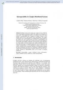
3
and a railway crossing. The latter is further called a level crossing as the road and the railway are crossing at same level. There is a common crossing area, where without any safeguarding road tra�c and trains would potentially collide. Measures have to be taken for the mutual exclusion of trains and road tra�c. Usually, this is realized by gates which can be closed to prevent motorists from entering the crossing area, and by railway signals telling an approaching train to stop when the gates are still open. In our example we assume the level crossing to be equipped with long arm gates, closing on each side of the level crossing both entry and exit lanes simultaneously. To be certain, that the area between the lowered gates is free from obstacles, an external level crossing monitor system is installed, con rming that no car is trapped in between the gates. Conventionally, a train approaching the level crossing is detected by line side equipment or signal sta�, such that the crossing gates can be lowered in time to let the train pass through without any delay or braking action. In future, this line side equipment or sta� shall not be necessary anymore, due to economic reasons. Therefore a solution has been developed that is based on self localization of the train and mobile communication with an autonomous level crossing control system. Self localization is realized through balises, i. e. small communication devices on the track, transmitting a unique identi cation to the train and referencing this identi cation to a digital route map stored on board the train. The route map contains the positions of all potential danger points, especially level crossings. If the onboard system detects, that the train is approaching a level crossing it will set a braking curve ending at this potential danger point. Also it will send a radio message to the level crossing control system to close the crossing gates in time. When the gates are closed and no car is trapped, which can be checked by an obstacle detection system, the level crossing control system will answer with its safe state to the train. Then the train can cancel the braking curve and safely pass over the level crossing. Triggering the exit contact will allow the gates to be opened again. This scenario describes the regular behaviour for the passage of a train over a single level crossing without regarding multiple trains, di�erent types of gates or system failures. The corresponding interaction diagram is depicted in Figure 1. To complete the description of the system requirements for level crossings, further scenarios have to be formulated. Aiming at a system model, these scenarios have to be integrated to a full system description. In order to demonstrate the integration of scenarios, we introduce a second, slightly di�erent scenario, dealing with a failure case. Supposing a failure in the external level crossing monitor system, the level
crossing control system cannot determine the crossing area to be free of obstacles after having closed the full arm gates. Thus it cannot answer its safe state to the train. Accordingly the train will not cancel the braking curve (speed limitation to zero) corresponding to the unsafe level crossing such that the speed supervision will trigger the brakes to stop the train safely before the potential danger point. At stand still, the driver is asked by the onboard system to check and then con rm the safe state of the level crossing on the manmachine-interface. When he has done so, the braking curve respectively speed limitation is cancelled and the train can pass over the level crossing. The opening of the gates is done as stated before. See Figure 2 for the corresponding interaction diagram.
OPEN NETS FOR COMPONENTS AND SCENARIOS
We describe at a semi-formal level the concept of open high-level Petri nets, and their use for modeling component scenarios of RCCS. Interaction diagrams, given in the previous section, will be translated into open nets, whose operational semantics faithfully represents the speci ed scenarios. The presentation will be generic with respect to the underlying notion of high-level nets (e.g. [PER95, Jen92]), but we shall make precise the special case of (low-level) placetransition nets.
Open High-level Nets An open high-level net is a high-level Petri net N which is augmented with a declaration of open places for modeling interaction with the environment. More formally, an open high-level net ON = (N; PO ; TO ; I; F) consists of a high-level net N with set of places PN and set of transitions TN , a subset PO � PN of open places, a subset TO � TN of observable transitions, and two sets of initial and nal markings I; F � Markings(PN ). A marking of a Petri net is an assignment of tokens to the places of the net. In a high-level net these tokens are not just black points but elements of a data type, like natural numbers, strings, or records. In general, Markings(P ) denotes the set of all possible markings for a subset P � PN of the places of N. In a place/transition net a marking is just a multiset m : P ! N assigning to each place p the current number of tokens m(p) 2 N. 0
0
0
From Interaction Diagrams to Open Nets
Interaction diagrams have been used for specifying scenarios of communication between a (set of) component(s) and the environment. Now we describe informally how to derive an open high-level net from such a diagram, and develop a corresponding 4
semantical understanding of open high-level nets. Assume an interaction diagram D which has C as a component. We call the net to be derived the scenario net SN(D; C) and use the interaction diagram for the regular case (RC) and the onboard control logic (OB) as example, see Figure 1. The idea of open places is to serve as `communication channels' between di�erent open nets modeling di�erent components; a message which is sent but not yet received is represented as a token on an open place. Hence, in the scenario net we need an open place for each component (and the environment) where the component C under consideration exchanges messages with. In the scenario net SN(RC; OB) in Figure 3, this results in the open places interface onboard/ balise, interface onboard/ route map, interface onboard/ speed supervision, interface onboard/ LC, and exit contact. The other (internal) places of this net model the temporal ordering of events (of sending and receiving messages), given by their positions on the vertical line: For each section between two such events there is an internal place, like wait representing the time between sending the bal id to interface onboard/ route map until receiving the answer dangerpoint(LC; pos). In addition, we have ENTRY and EXIT places for sequential composition of scenarios, representing respectively the top and bottom sections of the line. The communication events themselves are represented by transitions that are connected to the open places holding the corresponding messages, and to the internal places representing the vertical sections on the line. For an incoming message, like dangerpoint(LC; pos)from interface onboard/ route map, the open place is in the pre domain, while for outgoing messages like bal id it is in the post domain of the transition. Thus we obtain a chain of transitions connected through internal places. The de nition of the scenario net SN(RC; OB) in Figure 3 is completed by the initial and nal markings, having one token on ENTRY and EXIT, respectively. Similarly, we obtain scenario nets for the other components in the interaction diagram of Figure 1 as well as for the diagram specifying the failure case (FC) in Figures 2. Due to the space limitation we present only those nets needed to illustrate the composition of components and the integration of scenarios. These are SN(RC; OB), SN(FC; OB), SN(RC; LC), SN(FC; LC) in Figure 3 to Figure 6.
by consuming tokens from places in its pre domain and producing tokens in its post domain. If several transitions re in parallel, this is called a step of the net. The potential steps for a set of transitions T � TN in a net N are denoted by Steps(T ). For a place/transition net, such step is a multiset st : T ! N, giving the number of (self-concurrent) rings st(t ) of each transition t 2 T . For high-level nets assignments to variables at transitions might have to be recorded as well. A step st of N transforming a marking m into a marking m is written mN [st > mN . The behaviour of an open high-level net follows essentially the same rules, but allows additional spontaneous changes of the markings of open places. The arrival of a message, for example, is modeled by a token that just appears on an open place without being produced by a transition of the net. Hence, an open step m st m of ON is a parallel ring step mN [st > mN of the underlying net N, subject to the classical ring rules, which may be extended by spontaneous e�ects on the open places PO , that is m st m i� m = mN + mO ; m = mN + mO and mN [st > mN where mN ; mN 2 Markings(PN ) and mO ; mO 2 Markings(PO ). An open step sequence in ON is a sequence of open steps that begins in an initial marking and ends in a nal one. With respect to the aim of modeling scenarios however, this operational interpretation of open nets still contains too much information. In fact, a scenario only represents the interaction of a component with its environment in terms of communication events (i.e., sending and receiving of messages) but not the component's local computations or its intermediate states. Abstracting from internal actions, we consider only the ring of observable transitions TO , that is, those which are connected to (at least) one of the open places of the net. Then, an observable step sequence is obtained from an open step sequence by restricting it to observable transitions, hiding from each step m st m all transitions not connected to an open place. This leads st to an observable step m TO m . Then we just forget about the intermediate states and de ne a scenario of an open net ON as a sequence of observable steps os1 os2s: : : such that there exists an open step sequence m0 m1 s : : : where osi = si jTO is the restriction of si to observable transitions. Notice that these reductions do not a�ect the operational behavior of the net but just represent a more abstract view of it. In fact, two components that di�er only for their implementation but have the same observable behavior shall be considered as observationally equivalent, that is, we can replace one with the other without 0
0
0
0
0
0
0
0
0
0
0
0
0
0
0
0
0
j
1
Scenarios as Operational Semantics of Open Nets The classical operational semantics of a Petri
net is given by the token game: A transition may re
5
0
2
a�ecting the overall behavior. This fact is essential for the aim of interoperability of components. The scenario net SN(RC; OB) permits only one observable step sequence from the initial to the nal marking, that is, the original scenario for that component given by the interaction diagram. This determinism is typical for scenario nets.
and transition. The integration of the scenarios of the regular case and the failure case of the railway crossing can be done by integrating the scenario nets of the di�erent components. We illustrate the integration of SN(RC; OB) and SN(FC; OB). The scenario nets are identical except for the part between the places not allowed to pass level crossing and level crossing safe. The union yields the net SN(RC + FC; OB) with the two transitions process new status of level crossing and
INTEROPERABILITY USING COMPOSITION AND INTEGRATION OF SCENARIO NETS
detect train stop due to unsafe level crossing
in
In the previous section we have obtained the scenario net, we now want to illustrate the composition of components and the integration of scenario nets. We use in this paper inclusions and assume that open places in di�erent scenario nets have the same name, if they present the same communication. Moreover, open places in scenario nets of di�erent components and different scenarios must have di�erent names.
1
1
2
1
domain
of
place
2
1
1
Compatibility of Composition and Choice Integration In several cases, especially in all cases of
the composition of components, namely the composition of SN(RC; OB) and SN(RC; LC). The composition of components is obtained by fusion of the scenario nets at the open places that represent the communication between these components. In the case of SN(RC; OB) and SN(RC; LC) these are the places interface onboard/LC and exit contact. Now the communication is considered to be internal, thus these places become closed. More formally the fusion of components is given along the intersection of open places of both components and the set of open places for the resulting scenario net SN(RC; OB + LC) is given by the the union of the open places of both components without those places that are used for the fusion. These become closed. Thus, in general composition of components is given by fusion { a standard operation on Petri nets { along the set of common open places, denoted by Comp(C1 ; C2) = C1 + C2. The set of open places for the composition is given by POComp(C ;C ) = (PO C [ PO C )n(PO C \ PO C ) 2
post
communication with the environment remains the same, the set of open places is given by the union of open places. Thus, in general choice integration of alternative scenario nets is given for open nets D1 and D2 by union of nets: Int(D1 ; D2 ) = D1 [ D2 and the set of open places is computed by union of sets:POInt(D ;D ) = POD [ POD
Composition of Components First, we illustrate
1
the
not allowed to pass level crossing, see Figure 7. As the
our case study as considered in a simpli ed version in this paper, integration can be done by union of scenario nets. This requires that both scenarios have a common part such that integration can be realized by union without further synchronization. For this kind of choice integration we can show compatibility of composition and choice integration. Composition of scenario nets SN(D; Ci )i I for different components (Ci )i I followed by choice integration is equal to choice integration of scenario nets SN(Dj ; C)j J for di�erent scenarios (Dj )j J followed by composition. More precisely, we have: 2
2
2
2
INTj2J (COMPi2I (SN (Dj ;Ci ))) = COMPi2I (INTj2J (SN (Dj ;Ci )))
We illustrate this compatibility in case of two components and two scenarios for the sake of clearness. Given the scenario nets SN(D1 ; C1) and SN(D1 ; C2) for components C1 and C2 of one scenario represented by diagram D1 and SN(D2 ; C1) and SN(D2 ; C2) the same components of a di�erent scenario represented by diagram D2 . Then we have due to the compatibility of union and fusion [PER95]:
2
Integration of Scenario Nets The integration
of scenario nets can be divided into choice integration (of alternative scenarios) and coordination (of concurrent scenarios). In this paper we will merely discuss the rst one, that is obtained by union of nets. Alternative scenarios describe a similar situation that evolves di�erently. Thus they have a common beginning and ending, at least the entry and exit places are common to both. The integration of alternative scenarios can be considered as the union of the open nets, de ned by the union of places
Int(Comp(SN (D1 ; C1 ); SN (D1 ; C2 )); Comp(SN (D2 ;C1 ); SN (D2 ;C2 ))) SN (D1 ;C1 ) + SN (D1 ;C2 )) [ (SN (D2 ; C1 ) + SN (D2 ; C2 )) = (SN (D1 ;C1 ) [ SN (D2 ; C1 )) + (SN (D1 ; C2 ) [ SN (D2 ;C2 )) = Comp(Int(SN (D1 ; C1 );SN (D2 ; C1 )); Int(SN (D1 ;C2 ); SN (D2 ;C2 ))) = (
The computation of the open places commutes as well, we have: POInt(Comp(SN (D1 ;C1);SN (D1 ;C2));Comp(SN (D2 ;C1);SN (D2 ;C2))) Comp(Int(SN (D1 ;C1);SN (D2 ;C1));Int(SN (D1 ;C2);SN (D2 ;C2))) = PO
Using the formal techniques for high-level nets presented in [PER95, Pad96] based on colimit construc6
tions in category theory, this result can be shown on a formal level using general results of category theory concerning commutativity of colimit constructions (see e.g. appendix of [EM90]).
responding scenario nets. More particularly, it can be observed in this case that the scenarios implemented by SN(OB; RC + FC) form exactly the union of the scenarios of SN(OB; RC) and SN(OB; FC). In general it is likely to happen that, when coordinating di�erent (concurrent) scenarios, some of the original scenarios are lost, that is, they are no longer implemented by the integrated net. On the other hand, the new net may allow scenarios that were not available from the original speci cation, and which can arise from the combination of di�erent choices. It makes sense to explore these new scenarios since they represent integrated behaviours that have not been explicitly speci ed, and which are likely to occur also in the implemented system. One way of doing this is to use the same technique of interaction diagrams and their translation into open nets in order to specify forbidden scenarios (like the collision of two trains), and to test if the integrated net accidentally permits a forbidden scenario.
Testing of Integrated Scenario Nets Against Scenarios of Interaction Diagrams The scenario
nets derived from interaction diagrams have to undergo a number of integration and composition steps before they specify completely the observable behaviour of a meaningful subsystem of RCCS. Some of these steps are rather standard, like the composition of component nets and the choice integration of alternative scenarios, but in the case of concurrent scenarios the integration task may be non-trivial. In such cases, it makes sense to test if the component or subsystem nets implement all the original scenarios of the interaction diagrams. The idea is to use again the construction of scenario nets from interaction diagrams and to compare the semantics of the so-constructed scenario nets with the semantics of the subsystem net. For this it is important, that the scenario net and the subsystem net to be tested model the same part of the system, i.e., the same subset of components. Hence, we have to generalize the construction of a scenario net SN(D; C) for a single component C in an interaction diagrams D to a net SN(D; C1 + : : : + Cn) for several components C1 ; : : :; Cn. Then, all subsystem nets that claim to model the subsystem given by the components C1 + : : : + Cn have to implement at least the scenarios of SN(D; C1 +: : :+Cn ). More precisely, let SN(D; C1 + : : : + Cn) be a scenario net and ON be an arbitrary open net such that ON has all the observable transitions of SN(D; C1 + : : : + Cn), that is, TO � TO . Then, ON implements the scenarios of SN(D; C1 + : : : + Cn) if for each scenario s1 s2 : : : of SN(D; C) there is a scenario s1 s2 : : : of ON such that si jTO = si , that is, they coincide on the smaller set of observable transitions TO . We allow more observable transitions in ON since, typically, this shall be a nondeterministic net describing a scenario group from the point of view of a certain subsystem, while (as pointed out above) SN(D; C1 +: : :+Cn ) only represents a single scenario of that subsystem. Hence there may be more observable transitions in ON modeling events of alternative scenarios. For the nets of the RCCS speci cation this means to verify e.g., that the net SN(OB; RC + FC) (describing the onboard system) obtained as integration of the scenario nets SN(OB; RC) and SN(OB; FC) (for the regular and the failure case) implements the scenarios of SN(OB; RC) and SN(OB; FC). In our simple example, this is a direct consequence of the fact that SN(OB; RC + FC) is just the union of the cor-
CONCLUSION Overview and General Methodology In this pa-
per we have studied scenarios and interoperability problems. We have represented scenarios by interaction diagrams and shown how to construct in a canonical way an open net, called scenario net, for each component of a scenario, where open nets are high-level nets with distinguished subsets of open places and observable transitions. Interoperability in our approach is modelled by integration of component nets for di�erent scenarios and composition of di�erent component nets corresponding to the same scenarios. The techniques and the compatibility result of composition and integration shown in our RCCS case study can be applied to train control systems in general, especially for other problems in the area of ETCS. The general methodology of our approach is the following: 1. Modeling of scenarios by interaction diagrams 2. Construction of a scenario net for each essential component of each interaction diagram 3. Integration and composition of scenario nets. In particular coordination corresponding to concurrent scenarios should be done { as far as possible { on basic components rst, before composition. The order of choice integration and composition steps is not essential due to our compatibility result. 4. Testing of integrated and composed scenario nets with respect to required and forbidden scenarios. This is particularly important when concurrent scenarios have to be coordinated.
0
0
0
0
0
0
0
0
0
0
7
Future research We are aware that both kinds of integration, called choice integration and coordination, have to be studied in more detail in order to model real problems in the area of ETCS. Moreover, the informal presentation in this paper is only a rst step towards a formal theory of interoperability of scenarios in tra�c guidance systems using open nets. In forthcoming papers we will study the following aspects in more detail: 5. Techniques for coordination of scenario nets 6. Relationship between our notion of interaction diagrams and various notions of message sequence charts in the literature 7. Formal presentation of open nets, scenario nets and implementation of scenarios resp. scenario nets by open nets and coalgebraic semantics for open nets similar to graph transformation systems in the sense of [HEWC97] 8. Formal presentation of integration and composition of scenario nets using notions of category theory and proof of compatibility of composition and choice integration 9. Analysis of open nets concerning forbidden scenarios, as well as safety and liveness properties formulated in terms of temporal logic 10. Extension of techniques for compositional veri cation from algebraic high-level nets as studied in [PGE97] to open nets
[FHSGPJ96] D. Firesmith, B. Henderson-Sellers, I. Graham, and M. Page-Jones, Speci cation of the Common Object Modeling Notation (COMN), Version 0.5, http://199.72.157.5/oml-05/, 1996, Final Draft. [Gli95] M. Glinz, An Integrated Formal Method of Scenarios Based on Statecharts, 5th European Software Engineering Conference, 1995. [HEWC97] R. Heckel, H. Ehrig, U. Wolter, and A. Corradini, Double-Pullback Transitions and Coalgebraic Loose Semantics for Graph Transformation Systems, Submitted, 1997. [HM96] C. Heitmeyer and D. Mandrioli (eds.), Formal Methods for Real-Time Computing, John Wiley & Sons, 1996, Series Trends in Software vol 5. [HSG+ 94] P. Hsia, J. Samuel, J. Gao, D. Kung, Y. Toyoshima, and C. Chen, Formal Approach to Scenario Analysis, IEEE Software (1994), no. 11, 33{41. [Jen92] K. Jensen, Coloured Petri nets. basic concepts, analysis methods and practical use, vol. 1, Springer, 1992. [JLPS97a] A. Janhsen, K. Lemmer, B. Ptok, and E. Schnieder, Formal speci cations of the European Train Control System, IFAC Transportation Systems, 8th Symposium on Transportation Systems, 1997. [JLPS97b] A. Janhsen, K. Lemmer, B. Ptok, and E. Schnieder, Modelling and Simulation of the new European Train Control System, 2nd MathMod, Vienna, Austria, 1997. [JR91] K. Jensen and G. Rozenberg (eds.), HighLevel Petri-Nets: Theory and Application, Springer-Verlag, 1991. [Pad96] J. Padberg, Abstract Petri Nets: A Uniform Approach and Rule-Based Re nement, Ph.D. thesis, TU Berlin, 1996, Shaker Verlag. [PER95] J. Padberg, H. Ehrig, and L. Ribeiro, Algebraic high-level net transformation systems, Mathematical Structures in Computer Science 5 (1995), 217{256. [PGE97] J. Padberg, M. Gajewsky, and C. Ermel, Rule-Based Re nement of High-Level Nets Preserving Safety Properties, Accepted for FASE '98, 1997. [Rei85] W. Reisig, Petri nets, EATCS Monographs on Theoretical Computer Science, vol. 4, Springer-Verlag, 1985. [WRE95] H. Weber, W. Reisig, and H. Ehrig, Konzeption, theoretische Fundierung, und Validierung einer anwendungsbezogenen Petrinetz-Technologie, Antrag fur eine
References [BFJZ93]
K. M. Benner, M. S. Feather, W. L. Jofnson, and L. A. Zorman, Utilizing Scenarios in the Software Development Process, Information System Development Process (N. Prakash, Rolland. C., and B. Pernici, eds.), Elsevier Science Publisher, noth Holland, 1993, pp. 117{134. [DFKM97] J. Desharnais, M. Frappier, R. Khedri, and A. Mili, Integration of Sequential Scenarios, Proc. ESEC / FSE'97, Springer LNCS 1301, 1997, pp. 310{326. [Ehr97] H. Ehrig et al., Integration von Techniken der Software Spezi kation fur ingenieuwissenschaftliche Anwendungen, Antrag fur ein Schwerpunktprogramm an die DFG, 1997, (akzeptiert als DFG-SPP). [EM90] H. Ehrig and B. Mahr, Fundamentals of algebraic speci cation 2: Module speci cations and constraints, EATCS Monographs on Theoretical Computer Science, vol. 21, Berlin, 1990. [EMP97] H. Ehrig, A. Merten, and J. Padberg, How to Transfer Concepts of Abstract Data Types to Petri Nets, EACTS Bulletin 62 (1997), 106{104.
8
Forschergruppe an die DFG, 1995, (akzeptiert als DFG-Projekt von April 1996 bis Marz 1999).
9
FIGURES Scenario: Level Crossing with Long Gates, Full System Supervision, Regular Case Interaction Diagram (over all components)
MMI
Odometer Unit
Onboard System Speed Supervision
Balise Interface
Route Map
Onboard Control Logic (OB)
Level Crossing (Gates, G)
Level Crossing Control System (LC)
Exit Contact
gram
balise tele bal_id LC, pos
point (0,pos)
set speed limitation
request(close)
signal(close
gates)
s closed)
signal(gate
external level crossing monitor
signal(exit) status(closed)
tion point (pos)
delete speed limita
odo(level_crossing_pos)
Physical Transportation Process
polling (odo = pos)
physical contact
signal(exit) signal(ope
n gates)
)
s opened
signal(gate
Figure 1: Interaction Diagram for Regular Case Scenario: Level Crossing with Long Gates, Full System Supervision, Failure Case Interaction Diagram (over all components)
MMI
Odometer Unit
Onboard System Speed Supervision
Route Map
Balise Interface Onboard Control Logic (OB)
Level Crossing (Gates, G)
Level Crossing Control System (LC)
Exit Contact
gram
balise tele bal_id LC, pos
point (0,pos)
set speed limitation
request(close)
signal(close
gates)
s closed)
signal(gate
external level crossing monitor
signal(exit)
X
(odo,v)(in with brakintersection g curve)
Braking System
polling (v = braking curve (odo))
apply brake
stand still (v=0)
driver info (confirm level crossing
safe)
polling (v = 0)
confirmation level crossing safe
Braking System
tion point (pos)
cancel speed limita
release brake
level_crossing_pos
Physical Transportation Process polling (? = pos) physical contact
signal(exit) signal(ope
n gates)
)
s opened
signal(gate
Figure 2: Interaction Diagram for Failure Case 10
Level Crossing, Under Full System Supervision, Failure Case Onboard
SN(FC,OB) ENTRY
()
Level Crossing, Under Full System Supervision, Regular Case
balise overpassed
Onboard
SN(RC,OB)
bal_tg (bal_id, odo)
interface onboard / balise
()
ENTRY balise identification
()
balise overpassed
()
bal_tg (bal_id, odo)
interface onboard / balise
bal_id
look up danger point
()
bal_id interface onboard / route map
balise identification
wait
()
bal_id danger point(LC,pos)
bal_id
level crossing detected
look up danger point pos
() interface onboard / route map
level crossing unsafe
wait
pos set braking curve and request gates closed
() danger point(LC,pos)
level crossing detected
request(close)
interface onboard / LC
pos
not allowed to pass level crossing
pos
pos
level crossing unsafe
interface onboard / odometer
odo
detect train stop due to unsafe level crossing (pos = odo)
pos pos
set speed limitation point(0,pos)
set braking curve and request gates closed
driver has to deal with the situation
request(close)
pos
interface onboard / speed supervision
pos
not allowed to pass level crossing
driver_info ("confirm level crossing safe")
interface onboard / LC
pos
pos
process new status of level crossing
ask driver for confirmatioin of level crossing safe
interface onboard / MMI
status(closed)
wait for driver confirmation
pos
pos
confirmation level crossing safe
level crossing safe
process confirmation level crossing safe entered by driver
()
pos cancel speed limitation point(pos)
level crossing safe set speed limitation point(0,pos)
cancel braking curve
()
cancel braking curve
() cancel speed limitation point (pos)
passing over level crossing
() interface onboard / speed supervision
()
passing over level crossing
()
exit level crossing area
passed
exit contact exit level crossing area
passed
exit contact
() ()
EXIT EXIT 13.11.1997 13.11.1997
Figure 3: Scenario Net Onboard, Regular Case
Figure 4: Scenario Net Onboard, Failure Case
11
Level Crossing, Under Full System Supervision, Regular Case Level Crossing Control System
SN(RC,LC) idle: level crossing unsafe
Level Crossing, Under Full System Supervision, Failure Case
()
request(close)
Level Crossing Control System
process request
SN(FC,LC)
()
idle: level crossing unsafe
request
()
()
close gates
interface onboard / LC
signal(close)
request(close)
process request
()
() interface onboard / LC
wait for gates closing
interface LC / gates
request ()
process new gate status
()
signal(closed)
close gates
() gates closed, but no signal from external monitor
()
()
process signal from external monitor
signal(close)
wait for gates closing ()
interface LC / external monitor
interface LC / gates
()
()
process new gate status
signal(closed)
level crossing safe
() ()
status(closed)
gates closed, but no signal from external monitor
send level crossing status to onboard system ()
()
wait for passage
process exit signal
passed exit contact
()
() process exit signal
passed
exit contact
gates may be opened ()
()
gates may be opened
open gates
()
open gates
signal(open)
signal(open)
()
()
wait for gates opening
wait for gates opening
()
process new gate status
process new gate status
signal(opened)
signal(opened)
()
idle: level crossing unsafe
idle: level crossing unsafe
13.11.1997 13.11.1997
Figure 6: Scenario Net Level Crossing Control System, Failure Case
Figure 5: Scenario Net Level Crossing Control System, Regular Case
12
Level Crossing, Under Full System Supervision, Regular and Failure Case Onboard
SN(RC+FC,OB) ENTRY
()
balise overpassed
bal_tg (bal_id, odo)
interface onboard / balise
bal_id
balise identification
bal_id bal_id look up danger point
() interface onboard / route map
wait
() danger point(LC,pos)
level crossing detected
pos
level crossing unsafe
() set speed limitation point(0,pos)
set braking curve and request gates closed
request(close)
pos
not allowed to pass level crossing
pos
interface onboard / odometer
odo
interface onboard / LC
detect train stop due to unsafe level crossing (pos = odo) pos
driver has to deal with the situation pos driver info ("confirm level crossing safe")
pos
ask driver for confirmation of level crossing safe pos
interface onboard / MMI
wait for driver acknowledgement
pos confirmation level crossing safe
process confirmation level crossing safe entered by driver
process new status of level crossing
status(closed)
() pos
level crossing safe
pos
interface onboard / speed supervision
cancel speed limitation point (pos)
cancel braking curve
()
passing over level crossing
()
exit level crossing area
passed
exit contact
()
EXIT 13.11.1997
Figure 7: Integrated Scenario Net Onboard 13