Interpolation Algorithm and Mathematical Model in Automated ...
Recommend Documents
MARCO VIGNATI. 2. Uniform convexity. ..... [Her] E. Hernandez, Intermediate spaces andd the complex method of interpolation for families of Banach spaces ...
Apr 27, 2013 - Therefore, gray prediction models based on curve fitting and ... sample library features, the cubic polynomial fitting curve of the higher precision ...
computer algorithm, which we call the Automated Numerical Index Executor (ANIE) program for indexing PDFs, .... center, and the poles perpendicular to planes of all PDFs ..... The first one arises when there are multiple possible solutions that.
Apr 12, 2010 - The Guruswami-Sudan list decoding algorithm [1] is one of the most ...... and A. Vardy, âDivide-and-conquer interpolation for list decoding.
Sep 19, 2015 - efficiently partitioned into overlapping link communities by the genetic algorithm. Keywords. Bipartite Network, Link Community, Quantity ...
Feb 14, 2017 - [5], stowage planning [6], yard crane scheduling [7], and yard block allocation [8]. ..... is referred to as scaling factor controlling the mutation scale, which is .... permutation, to avoid wasteful duplication of conversion between
Oct 12, 2001 - as a mathematical program with equilibrium constraints (MPEC). ... The common point in all these traffic management models is that the main ...... also other approaches are possible to apply; we refer to the MPEC text books.
Automated Design, Integration and Operation of Chemical. Processes ... programming models for the synthesis of reactor networks, distillation sequences, heat.
Unstretched laminar burning velocity, Markstein lengths, Lewis number, ... equivalence ratio influnced Markstein lengths to be decrease for the tested blends-air.
The Iraqi Journal For Mechanical And Material Engineering, Vol.14, No1, 2014. 153. THE EFFECT 0F ... Dr. Jassim Mohammed Salman Al-Murshdy. Mr. Haydar ... From DSC curves could conclude the alloys that quenched in polymer solution have been ..... Inc
top dead centre. INTRODUCTION. The alcohols are fuels of the family of oxygenates. As is known to all, the alcohol molecule has one or more oxygen atoms, ...
Blending of two or more types of polymer is a useful technique for preparation and developing ... statement is also true with rubber blends, especially in tire manufacture[F. Findik 2004 and ... trees [Kaushik Pal 2010 and C.A. Harper 2000].
The Iraqi Journal For Mechanical And Material Engineering, Vol.15, No2, 2015 .... section helical spring with one end fixed and the other end free, the natural .... When notches are necessary, removal of material near the notch can improves the stren
Motion, Velocity and Acceleration of System of Two Components .... the outside shape surface of the cams itself and vehicle speed. Cam-tire tangential point .... At the moment of the end of the load stroke, flywheel- generator system should be ...
In [1], Paul Zeitz discusses how to solve mathematical problems. ... This is the
eureka step that Paul Zeitz was. 1 ... P Zeitz. The Art and Craft of Problem Solving
.
Apr 14, 2016 - ISSN: 2329-6542. Research Article. Open Access. A Mathematical Model of the Maximum Rigidity Resulting from Diffusive. Shock Acceleration.
a (minimal) state space realization of a rational function. Model order .... methods that can be used for solving the rational interpolation problem. These are the ...
Sami A. Nama. OF A HELICAL MACHINED SPRING. 182. NOMENCLATURE b = wire side length (mm). C = spring index. d = diameter of spring wire (mm).
A new prosthetic foot is designed and manufactured from polyethylene and a ..... 3- R. Deval "The Seattle Foot" J.oF Orthotics and Prosthetics Vol.40, No.8, ... Ankle â Foot Prostheses as Exemplified by the Jaipur Foot " J. of Rehabilitation.
Sep 7, 2014 - mal reduced models at modest cost; refined methods for deriving inter- polatory reduced models directly from input/output measurements; and.
Mar 1, 2016 - arXiv:1509.09271v2 [quant-ph] 1 Mar 2016 ... Meyer and Pommersheim shows that d/2+1/2 quantum queries are needed to solve this problem.
... of the standard IDW, which is originated by Lu and Wong.32 The basic and most ...... Wei, Haitao Du, Yunyan Liang, Fuyuan Zhou, Chenghu Liu, Zhang Yi,.
More precisely, we consider the following implicit interpolation problem: Problem 1 ... mined by the sequence F1,...,Fn
Interpolation Algorithm and Mathematical Model in Automated ...
1. Introduction In the production of pressure vessels, the welding problem between the cylinder and the pipe is often encountered, and sometimes a pressure vessel needs to weld dozens or even hundreds of pipes. In the project, the intersecting line, called the three-dimensional standard saddle-shaped weld, is formed by the combination of two orthogonal cylinders. Also, according to the different groove form, the multilayer continuous welding is required [1, 2]. Saddle-shaped weld is a complex space curve. In order to complete the welding work of the saddle seam, manual welding operation is still widely adopted. However, by doing this the welding quality and efficiency requirements are uncertain. Thus, the automation of the welding process is greatly significant. With the development of automatic welding system, obvious progress has been made in recent years. According to the welding process of saddle seam, there are two ways to build the automated welding system. One is to equip welding robots in their welding system; the other is to develop specially designed automated welding system. One of the most promising ways is to adopt proper curve interpolation algorithm in automated welding system [3]. Huo et al. [4] presented a real-time interpolation algorithm, which fits the
intersecting curve with step-controllable segments. Ren et al. [5] established a geometrical model of the interpolation pipe’s weld seam and integrated the posture of the welding torch. Zhiming et al. [6] presented a real-time interpolation algorithm for NURBS curves; the proposed interpolator can maintain small contour errors and feed rate fluctuations. Real-time nonuniform rational B-spline interpolation algorithms were also introduced [7–9]. Tam et al. [10] proposed an algorithm for the interpolation of hybrid curves, based on interpolation of the projection of the hybrid curve into the parametric domain. Srijuntongsiri [11] proposed a new iterative hybrid algorithm to detect all intersections in the domain for nondegenerate and non-ill-posed cases. Direct interpolation algorithms [12, 13] do not have satisfied linear velocity control ability because welding quality is very sensitive. Only interpolation algorithm with ideal trajectory precision and linear velocity control ability can meet requirements of welding. In this paper, a spatial interpolation algorithm for the saddle-shaped curve is proposed by using the variable angle interpolation control method for the interpolation stepping angle and establishes welding torch pose model and trajectory model based on space analytic geometry. Simulation of the interpolation algorithm has been carried out to verify the
2
Modelling and Simulation in Engineering X
r Z 0
A O
Pi+1 (xi+1 , yi+1 ) Δ
Pi (xi , yi )
i i+1
Y
Y
X
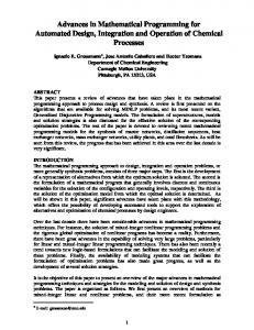
Figure 1: Saddle weld and the reference frame configuration.
correctness of the proposed algorithm and mathematical model. It demonstrates that algorithm has high trajectory precision and the mathematical model meets the requirements of welding.
Figure 2: The circular interpolation diagram.
3.1. The Circular Interpolation. Let point 𝑃𝑖 (𝑥𝑖 , 𝑦𝑖 ) and 𝑃𝑖+1 (𝑥𝑖+1 , 𝑦𝑖+1 ) be the current and next interpolation point on the saddle weld and the angle of the 𝑥-axis, respectively; 𝜃𝑖 and 𝜃𝑖+1 be the angles between the two points for the Δ𝜃, 𝜃𝑖+1 = 𝜃𝑖 + Δ𝜃, and the coordinates of the 𝑃𝑖 point are 𝑥𝑖 = 𝑟 sin 𝜃𝑖 𝑦𝑖 = 𝑟 cos 𝜃𝑖 .
2. Working Principle of Welding Machine In this paper, the typical saddle-shaped weld is formed by the combination of two orthogonal cylinders and the pipe is taken as an example to illustrate the working principle of the saddle-shaped welding system, as shown in Figure 1. The coordinate system 𝑂-𝑥𝑦𝑧 is established by the intersection of the cylinder and the axis of the pipe, selecting the saddleshaped weld left side of the highest point 𝐴 as the starting point of welding. The 𝑥- and 𝑦-axis two directions are driven by the entire welding system to achieve rotary motion. The 𝑧-axis direction is driven by the torch to achieve up and down reciprocating motion, which is also as a compensation movement to achieve saddle drop compensation. At the same time, the upper and lower movement of the output end are installed with angle adjustment mechanism; the welding torch is adjusted in real time with the rotary motion. According to the characteristic that this kind of weld joint in the horizontal 𝑥𝑂𝑦 surface is round, based on the twodimensional plane circular interpolation algorithm, the interpolation of saddle space weld can be decomposed into two two-dimensional interpolations [4]. The first interpolation is the 𝑧-axis vertical direction interpolation, and the second interpolation is an interpolation of horizontal rotation angel [14, 15].
So the coordinates of 𝑃𝑖+1 can be expressed as 𝑥𝑖+1 = 𝑟 sin (𝜃𝑖 + Δ𝜃) = 𝑟 sin 𝜃𝑖 cos Δ𝜃 − 𝑟 cos 𝜃𝑖 sin Δ𝜃 = 𝑦𝑖 cos Δ𝜃 − 𝑥𝑖 sin Δ𝜃 𝑦𝑖+1 = 𝑟 cos (𝜃𝑖 + Δ𝜃)
(2)
= 𝑟 cos 𝜃𝑖 cos Δ𝜃 − 𝑟 sin 𝜃𝑖 sin Δ𝜃 = 𝑥𝑖 cos Δ𝜃 − 𝑦𝑖 sin Δ𝜃. When 𝜃𝑖+1 ≤ 2𝜋, then continue interpolating; when 𝜃𝑖+1 > 2𝜋, to amend the last step Δ𝜃, there will be an interpolation stepping Δ𝜃 ; then, Δ𝜃 = 2𝜋 − 𝜃𝑖 . So the new position of the interpolation point projected in the 𝑥𝑂𝑦 plane can be expressed as 𝑥 = 𝑟 sin (𝜃𝑖 + Δ𝜃) 𝑦 = 𝑟 cos (𝜃𝑖 + Δ𝜃)
(3)
𝜃𝑖+1 = 𝜃𝑖 + Δ𝜃, where 𝜃𝑖 is the current angle, 𝜃𝑖+1 is the angle of the next point, and Δ𝜃 is the added value of the angle. Based on the principle of space analytic geometry, we have 𝑥2 + 𝑦2 − 𝑟2 = 0
3. Research of Saddle-Shaped Weld Interpolation Algorithm Given that the radius of the cylinder is 𝑅 and the radius of the pipe is 𝑟, the projection of the saddle-shaped weld in the 𝑥𝑂𝑦 plane is shown as in Figure 2, 𝜃 being the angle parameter that can uniquely determine the pose of the point on the saddleshaped space curve.
Figure 4: The schematic diagram of linear velocity. X Z
Figure 3: Relation diagram between dihedral angle and pose angle.
Q
From (3) and (6), we also have 𝑧 = √𝑅2 − 𝑟2 + 𝑟2 cos2 (𝜃𝑖 + Δ𝜃) =
√𝑅2
−
𝑟2 sin2
O
X
3.2. Welding Torch Posture Interpolation. Choose a point in the saddle-shaped weld; dihedral angle of the point on saddle weld is the angle between the cylinder’s tangent plane through this point and the pipe’s tangent plane. Dihedral angle is not equal at different points on saddle weld. Therefore, 𝛽 is the dihedral angle of point 𝑄 on saddle weld (Figure 3). As can be seen from Figure 3, the diagonal angle at the starting point 𝐴 is 𝜋/2 and the initial pose angle is 𝜙 (regular angle of welding torch’s pose). Based on the principle of space analytic geometry, the equations of the cylinder and the pipes are given as
2
2
2
𝜑2 (𝑥, 𝑦, 𝑧) = 𝑥 + 𝑧 − 𝑅 = 0. as
(8)
Then the normal vectors→ n 1 and→ n 2 at point 𝑄 are defined 𝜕𝜑 𝜕𝜑 𝜕𝜑 → n 1 = { 1 , 1 , 1 } = {𝑥, 𝑦, 0} 𝜕𝑥 𝜕𝑦 𝜕𝑧 𝜕𝜑 𝜕𝜑 𝜕𝜑 → n 2 = { 2 , 2 , 2 } = {𝑥, 0, 𝑧} . 𝜕𝑥 𝜕𝑦 𝜕𝑧
(9)
Geometry is defined as → n2 n 1 ⋅→ 𝑥2 cos 𝛽 = → → = 𝑅 × 𝑟 . n 1 × n 2
(10)
From (3) and (10), we have 𝛽 = arccos (
𝑟sin2 (𝜃𝑖 + Δ𝜃) ). 𝑅
Y
(7)
(𝜃𝑖 + Δ𝜃).
𝜑1 (𝑥, 𝑦, 𝑧) = 𝑥2 + 𝑦2 − 𝑟2 = 0
V
(11)
It can be seen from Figure 3 that although dihedral angles of point on saddle weld differ from each other, they all have certain relationship with pose angle. As the rotation axis
Figure 5: Linear velocity direction.
rotates from point 𝐴 to point 𝑄, the dihedral angle changes from the original 𝜋/2 to 𝛽, and pose angle is supposed to change 𝜋/2 − 𝛽 in order to meet pose angle requirements. So expression of dihedral angle is as follows: 𝛿 = 𝜋/2 − 𝛽 + 𝜙. Put formula (11) into it; then 𝛿=
𝑟sin2 (𝜃𝑖 + Δ𝜃) 𝜋 − arccos ( ) + 𝜙. 2 𝑅
(12)
After the rotation angle changes Δ𝜃 from 𝜃𝑖 to 𝜃𝑖+1 , according to (3), (7) and (12) can calculate the coordinates of the new interpolation point 𝑃𝑖+1 (𝑥, 𝑦, 𝑧, 𝜃𝑖+1 , 𝛿). Selecting the appropriate Δ𝜃, one can obtain interpolation saddle weld by providing the cylinder and the pipe radius 𝑅, 𝑟, welding torch starting pose angle 𝜙. 3.3. Control Law of Variable Angle Δ𝜃. The control of the interpolation stepping angle Δ𝜃 is divided into equal angle interpolation and variable angle interpolation. Equal angle interpolation mode is to keep the stepping angle Δ𝜃 constant, and actual welding linear velocity of welding torch is not constant, affecting the quality of welding. Variable angle interpolation is to make every step interpolation stepping angle Δ𝜃 with 𝜃 to make a change. In the Δ𝑇 fixed conditions, welding linear velocity is constant and each step of the interpolation stepping-length will be equal, to ensure the welding of high quality. Select a point 𝑄 on the saddle-shaped weld; according to kinematics principle, linear velocity direction of the point 𝑄 is direction vector of intersection line of two intersection’s tangent planes at point 𝑄 (Figure 5). Suppose linear velocity of welding torch is 𝑉, interpolation cycle is Δ𝑇, and the angle between the 𝑧-axis and linear velocity is 𝛼 (shown in Figure 4).
4
Modelling and Simulation in Engineering As can be seen from Figure 4, 𝑟 ⋅ Δ𝜃 = V ⋅ Δ𝑇 ⋅ sin 𝛼 Δ𝜃 =
(13)
V ⋅ Δ𝑇 ⋅ sin 𝛼 . 𝑟
(14)
Set the coordinates of the 𝑄 point 𝑄 (𝑥𝑞 , 𝑦𝑞 , 𝑧𝑞 ). The tangent plane equation of the cylinder at the point 𝑄 is expressed as 𝑥𝑞 ⋅ (𝑥 − 𝑥𝑞 ) + 𝑧𝑞 ⋅ (𝑧 − 𝑧𝑞 ) = 0.
𝑥𝑞 2 𝑥𝑞 2 𝑟2 𝑅2 → − 𝑦𝑞 , − 𝑧𝑞 ) = (−𝑥𝑞 , , ) . (19) n 3 = (−𝑥𝑞 , 𝑦𝑞 𝑧𝑞 𝑦𝑞 𝑧𝑞 The direction vector of the 𝑧-axis is → n 4 = (0, 0, 1); one can get following equation: → 𝑥𝑞 /𝑧𝑞 n4 n 3 ⋅→ . cos 𝛼 = → = → n 3 n 4 2 2 √ 1 + (𝑥𝑞 /𝑦𝑞 ) + (𝑥𝑞 /𝑧𝑞 )
(20)
(15) Then
And then 𝑥𝑞 ⋅ 𝑥 + 𝑧𝑞 ⋅ 𝑧 = 𝑥𝑞2 + 𝑧𝑞2 = 𝑅2 .
(16)
Similarly the tangent plane equation of the pipe at the point 𝑄 is expressed as 𝑥𝑞 ⋅ 𝑥 + 𝑦𝑞 ⋅ 𝑦 = 𝑥𝑞2 + 𝑦𝑞2 = 𝑟2 .
(17)
2
sin 𝛼 = √1 −
The two points 𝑄 (𝑥𝑞 , 𝑦𝑞 , 𝑧𝑞 ) and (0, 𝑟2 /𝑦𝑞 , 𝑅2 /𝑧𝑞 ) are on the intersection line of two tangent planes, and the direction vector of the tangent line equation is calculated as
sin 𝛼 =
=
2
2
.
(21)
And because of the 𝑄 point in the saddle-shaped space curve, according to (3), we have 𝑥𝑞 𝑦𝑞
(18)
𝑥𝑞 ⋅ 𝑥 + 𝑦𝑞 ⋅ 𝑦 = 𝑥𝑞2 + 𝑦𝑞2 = 𝑟2 .
√ 1 + (𝑥𝑞 /𝑦𝑞 )
√ 1 + (𝑥𝑞 /𝑦𝑞 ) + (𝑥𝑞 /𝑧𝑞 )
Equations of intersection line of two tangent plans are 𝑥𝑞 ⋅ 𝑥 + 𝑧𝑞 ⋅ 𝑧 = 𝑥𝑞2 + 𝑧𝑞2 = 𝑅2
From (24), interpolation step angle Δ𝜃 changes in real time with the change of 𝜃𝑖 to ensure that practical linear velocity of the welding torch is kept constant so as to meet the requirement of the welding process.
radius of cylinder 𝑅 = 600 mm, the radius of pipe 𝑟 = 150 mm, the starting pose angle = 𝜋/4, and Δ𝑇 = 0.004 s. MATLAB simulation results are shown in Figures 6–11. The interpolation data of 𝜃 and (𝑥, 𝑦, 𝑧, 𝛿) by algorithm are shown in Table 1.
4. Simulation Results In order to verify the correctness of the mathematical model and algorithm, using programming takes simulation experiment, taking orthogonal saddle welding, for example, assume that practical welding parameters are as follows: the
5. Welding Experiment According to the welding process of the saddle weld, the main parameters of the welding experiment are listed in
Table 2. The photograph of the saddle seam surface is shown in Figures 12 and 13. Correct saddle seam is reflected in the photos, which verify the feasibility of the interpolation algorithm.
6. Conclusions According to the welding technology of saddle seam, the working principle of auto-welding machine for saddle-shaped
Coordinate of z, z/mm
Modelling and Simulation in Engineering
600 590 580 150
100
100 50 50 0 ya 0 ) xis m −50 (mm −50−100 is (m −100 ) x ax −150 −150
150
Figure 6: Simulation result of the trajectory interpolation algorithm. Pose angle of welding torch, /rad
350 345 340 335 330 325 320 315 310
0
1
2
3
4
5
6
7
Rotation angle, /rad
Figure 10: Simulation figure of the relationship between rotation angle and 𝑧-axis coordinate value.
1.05 1 0.95 0.9 0.85 0.8 0.75
0
1
2
3 4 Rotation angle, /rad
5
6
7
Coordinate of x, x/mm
Figure 7: Simulation figure of the relation between rotation angle and pose angle. ×104 2.5 2 1.5 1 0.5 0 −0.5 −1 −1.5 −2 −2.5 0
Coordinate of y, y/mm
0.202 0.2 0.198 0.196 0.194 0.192 0.19
0
1
2
3 4 5 Rotation angle, /rad
6
7
Figure 11: Relationship between rotation angle and interpolation step-length.
Table 2: Welding experiment parameters.
1
2
3 4 5 Rotation angle, /rad
6
7
Figure 8: Simulation figure of the relationship between rotation angle and 𝑥-axis coordinate value. ×104 2.5 2 1.5 1 0.5 0 −0.5 −1 −1.5 −2 −2.5 0
Interpolation step-length (mm)
z axis (mm)
6
1
2
3
4
5
6
7
Rotation angle, /rad
Figure 9: Simulation figure of the relationship between rotation angle and 𝑦-axis coordinate value.
Parameter Radius of cylinder Radius of branch pipe Welding type Welding current Arc voltage Welding speed Wire feed rate Wire diameter Pose angle Wire extension
Value 600 mm 150 mm GMAW 230 A 25.3 V 80 mm/min 6 m/min 1.2 mm 25∘ 12 mm
weld is proposed, and the mathematical model and interpolation algorithm of saddle-shaped weld are established. The interpolation algorithm can well meet the technical requirement of automatic welding and can achieve trajectory control of welding of saddle-shaped weld and can also achieve control of welding torch’s pose, to ensure better welding conditions. A variable angle interpolation method is used for realtime change interpolation stepping angle and to guarantee that practical linear velocity of the welding torch is kept constant and improve the quality of the weld seam.
Modelling and Simulation in Engineering
Figure 12: Photograph of the saddle seam surface.
Figure 13: Photograph of the saddle seam surface.
Conflicts of Interest The authors declare that there are no conflicts of interest regarding the publication of this paper.
Acknowledgments This research was supported by Xinjiang Production and Construction Corps Science and Technology Research and Achievement Transformation Project under Grant no. 2016AB004.
References [1] D. Tiequn, M. Fanrong, and S. Guanyuan, “Kinematic simulation on large cylinder saddle automatic welding machine base on ADAMS,” in Welding & Joining, pp. 64–66, 2008. [2] Hong Feng Wang, A Spreading Algorithm of an Intersecting Line.Computer Development & Applications, PP. 59-62, 2009. [3] X. Tian, X. Yi, and H. Chang, “Interpolation of saddle-shaped trajectory in non-Cartesian coordinate system,” Advanced Science Letters, vol. 19, no. 7, pp. 1927–1930, 2013. [4] M.-Y. Huo, X.-G. Wang, and P. Yin, “Real-time interpolation algorithm and simulation of seam of intersection line for automatic welding,” Hanjie Xuebao/Transactions of the China Welding Institution, vol. 27, no. 11, pp. 37–40, 2006. [5] F. Ren, S. Chen, S. Yin, and X. Guan, “Modeling on weld position and welding torch pose in welding of intersected pipes,” Hanjie Xuebao/Transactions of the China Welding Institution, vol. 29, no. 11, pp. 33–36, 2008. [6] X. Zhiming, C. Jincheng, and F. Zhengjin, “Performance evaluation of a real-time interpolation algorithm for NURBS curves,” The International Journal of Advanced Manufacturing Technology, vol. 20, no. 4, pp. 270–276, 2002.
7 [7] W. T. Lei, M. P. Sung, L. Y. Lin, and J. J. Huang, “Fast realtime NURBS path interpolation for CNC machine tools,” International Journal of Machine Tools & Manufacture, vol. 47, no. 10, pp. 1530–1541, 2007. [8] H. Dong, B. Chen, Y. Chen, J. Xie, and Z. Zhou, “An accurate NURBS curve interpolation algorithm with short spline interpolation capacity,” The International Journal of Advanced Manufacturing Technology, vol. 63, no. 9-12, pp. 1257–1270, 2012. [9] S.-I. Gofuku, S. Tamura, and T. Maekawa, “Point-tangent/pointnormal B-spline curve interpolation by geometric algorithms,” Computer-Aided Design, vol. 41, no. 6, pp. 412–422, 2009. [10] H.-Y. Tam, H. Xu, and P. W. Tse, “An algorithm for the interpolation of hybrid curves,” Computer-Aided Design, vol. 35, no. 3, pp. 267–277, 2003. [11] G. Srijuntongsiri, “An iterative/subdivision hybrid algorithm for curve/curve intersection,” The Visual Computer, vol. 27, no. 5, pp. 365–371, 2011. [12] H. Qi, X. Tian, X. Zhang, and B. Peng, “Interpolation algorithm for saddle-shaped curve auto-welding based on angle approaching,” Hanjie Xuebao/Transactions of the China Welding Institution, vol. 28, no. 3, pp. 93–96, 2007. [13] L. Yan, T. Xincheng, X. Qing, and P. Bo. Four-axis interpolation, “algorithm for saddle-shaped curve automated welding,” in P.Bo. Four-axis interpolation algorithm for saddle-shaped curve automated welding.Transactions of the China Welding Institution, vol. 30, pp. 81–84, Transactions of the China Welding Institution, 2009. [14] D. Weimin, G. Gmmbin, and S. Dongming, “Study on the errors and real-time of interpolation methods,” Machine Building & Automation, pp. 18–21, 2006. [15] Y. Changlong, L. Lix, and Z. Yonghui, “Simulation of welding intersecting cylinders line for welding robot,” Journal of Shen Yang University of Technology, vol. Vol, no. 05, pp. 426–429, 2003.