Image and Video Processing. Dr. Anil Kokaram
. The next
lectures introduce fundamental concepts in digital video processing. This
handout.
Introduction to Digital Video Processing Image and Video Processing Dr. Anil Kokaram
[email protected]
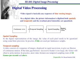
The next lectures introduce fundamental concepts in digital video processing. This handout covers the practical aspects of video formats. The goals here are • To understand the production of video signals • To introduce Analog Video Formats • To introduce Digital Video Formats • To introduce the image formation process • To introduce simple models for image sequences
1
Video and some History
A video signal is the term used to describe any sequence of time varying images. A still image is a spatial distribution of intensities that remain constant with time while a time varying image has a spatial intensity distribution that varies with time. Movies (films) and television are both examples of video signals as are the signals that drive computer monitor, laptop and PDA displays. It is widely expected that video communications in particular will be the next application driving the mobile and handheld device market. This course should give you the tools to understand the components that are necessary for such systems to operate effectively.
1.1
A Cinema History
Cinema is just over 100 years old. The date usually cited as the birth of cinema is 28th December 1895 when Auguste and Louis Lumi`ere showed their films to a paying audience in Paris. The development of their camera and projector can be traced back via a long line of developments to the invention of Faraday’s wheel in 1831 which illustrated the theory of the persistence of vision.
1
1.2
A Television History
1
VIDEO AND SOME HISTORY
Photography was explored in the 1840’s and photographs were being made in 1839 by William Henry Fox on silver halide paper. 1872 saw the first use of a series of images for recording movement (Eadweard Muybridge). When George Eastman produced paper roll film in 1885, Etienne-Jules Marey, inspired by Muybridge, built a camera that could take 100 pictures per second. Just 4 years later in 1889, Thomas Alva Edison developed a camera using celluloid film. He showed his films on a continuous loop in a peep-show type machine called the kinetoscope. It is this invention which impressed the Lumi`ere brothers sufficiently to attempt a public showing of cinema in 1895. The first purpose-built cinema appeared in 1906 (the Omnia-Path´e) in Paris. In the U.S. by 1908 there were nearly 10,000 nickelodeons attracting 20 million people weekly.
1.2
A Television History
The first television broadcast was made on November 2nd 1936 by the BBC from Alexandra Palace. It was with the broadcast of the coronation of King George VI on 12th May of that year, that television showed potential for rapid information dissemination. After shutting down for World War II in September 1939, television broadcasting resumed on 7th June 1946. In 1953 the Coronation of the Queen was watched in 3,000,000 homes and that event proved TV to be a genuine mass media device. Colour television was first broadcast in 1954 in the USA using the NTSC standard. Europe opted to evaluate different colour transmission schemes until 1967 when the PAL (Phase Alternate Line) broadcast standard was adopted for colour TV broadcast in the UK and Germany. The colour signal format was chosen so that people with black and white TV sets could still receive the signal, hence the YUV colour components discussed in previous lectures.
1.3
A History of Video Recording
Video recording devices came along much later than the TV. The early devices were invented in the 1950’s and RCA developed a machine with tape speeds of 6 metres/sec. They used longitudinal recording of the signal on the tape, so fast speeds were required to record the large bandwidth TV signal. The first practical video recorder was developed in 1953 by the Ampex Corporation. It used the helical scan arrangement which remains with us today and allows higher effective recording speeds without a frightening tape speed. The first home video equipment was developed by Philips in 1972 which was quickly superseded by the VHS machines of Panasonic and the Betamax machines of Sony in 1978. The arrival of these formats marked the start of the home video era. The ability to record and edit programmes made by the home user increased the popularity of TV. Sony lost the now famous marketing war by 1980 when VHS had become the main standard for home video users mainly due to its longer playing time. This was despite the superior quality of the Betamax format.
2
www.mee.tcd.ie/∼isd
2 RECORDING PICTURES AND CREATING VIDEO
2
Recording pictures and creating video
There are principally three technologies for recording time varying imagery. The first (and oldest) is that adopted by the Cinema industry and uses film cameras to take 24 pictures every second. The second is that initially adopted by television which used CRT tubes in cameras (Vidicon) to electrically record pictures. The most recent image acquisition technologies use the CCD (Charge Coupled Device) array to measure light intensity at specific spatial locations and thus create digital images within the acquisition device itself. CCD devices are extremely small, lightweight and have low power consumption. This makes them ideal for use in portable devices e.g. PDA’s and medical imaging devices (endoscopes). The recent trends in Digital Video have been driven by the availability of a swathe of digital video recorders all based on this acquisition technology.
2.1
The CCD
The CCD is a rectangular arrangement of semiconductors each of which converts light into electric charge (i.e. a unit of light is converted into a fixed amount of electrons). Electric charge accumulates in each semiconductor element for the entire time that the device is exposed to light. The rectangular arrangement is called an array. Pictures are acquired by exposing the array for a short exposure time, then the charge is converted into a voltage which is then assembled into the final video signal. 25 pictures a second generate European format video signals. (30 times a second for US standard.) Each element of the CCD array integrates light over a small unit area. This is the smallest resolvable element in the resulting image. This unit of image is called a pixel for Picture Element. The Texas Instruments TC237 (for instance)1 has 680 pixels on each of 500 lines in its array. The exposed surface is about .4 × .6cm2 , this gives a density of about 1.5 Million pixels per cm2 . This implies a very high resolution image. CCDs can suffer from leakage of charge from one pixel into nearby pixels. This causes a distortion in the image produced. It is called blooming. CCD device specs often state how much leakage occurs. To read out the charge accumulated at each pixel in the CCD it is necessary to clock the charge in each line out to a register which converts charge to voltage. That voltage signal is then incorporated into the output video signal to create analogue video, or it is digitised and processed to create an output digital video signal. To accurately measure light, the pixel elements in the CCD must stop accumulating charge while the measurement is being made. There are two ways in which this situation can be engineered and these are discussed next. 1
By now an old CCD device
3
www.mee.tcd.ie/∼isd
2.2
Types of CCD packages Light
LENS
2
Shutter
RECORDING PICTURES AND CREATING VIDEO Clock Signal
1 0 0 1 0CCD Array 1 0 1 0 1 0 1 0 1 0 1 0 1 0 1 0 1 0 1
CCD Element Clock Signal Shift Register
Image signal Image (voltage) out
Reset Exposure time 1111 0000 0000 1111 0000 1111 0000 1111 accumulate charge
Shutter Open
Shift into register and convert to video 11111111111111 00000000000000 00000000000000 11111111111111 00000000000000 11111111111111 00000000000000 11111111111111
Time
Shutter closes < 1/25 sec
Figure 1: Operation of the Full Frame Read-out CCD
2.2 2.2.1
Types of CCD packages Full Frame Read-out CCD (FF-CCD)
This CCD package closes the shutter after a short exposure time thus no more light is allowed to hit the array. The charge in each line of pixels is then shifted into a register where it is converted to a voltage. The next exposure time begins after this cycle of measurement begins. See figure 1. This device allows a large imaging area i.e. the full surface of the package. But the exposure time has to be short since it takes time to convert charge to a voltage in the shift register; and during this time the shutter must be closed to avoid charge accumulation. This means the sensitivity is low.
2.2.2
Frame Transfer CCD (FT-CCD)
In this device, an array of storage elements is placed next to the exposed pixel array. After each exposure interval, the charge in the exposed array is transferred quickly into the storage array. The storage array is principally the same material as the main array, but it is covered to prevent the elements accumulating charge. The next exposure time begins while the last image is being shifted/converted into a voltage by the shift register. See figure 2. The advantages of this device are that no shutter is needed and exposure times can be long hence the device can have high sensitivity. However, the imaging area is smaller than FF CCD, or the package size must be bigger for same imaging area.
2.2.3
Colour
CCDs acquire colour in one of two mechanisms. 4
www.mee.tcd.ie/∼isd
2.2
Types of CCD packages
2
RECORDING PICTURES AND CREATING VIDEO
Light Imaging Area
CCD Array LENS Isolation
Isolation Bank
Storage Image signal
Storage Area Image (voltage) out Shift Register Reset
Exposure time
Shift image into storage area Time
accumulate charge Shift previous image out of storage into video signal out
Time < 1/25 sec
Figure 2: Operation of the Frame Transfer CCD 1. Consecutive method: Illuminate the object with RGB light consecutively and record the output of the same CCD array each time. Store each frame CCD output for display after each frame is recorded. 2. Simultaneous method: Place a mosaic of filters over a single CCD which allows pixels to record RGB light separately. Figure 3 shows this.
SUBTRACTIVE COLOUR FILTER MASK CY
G
CY
G
CY=G+B
Y
G
Y
G
Y=R+G
CY
G
CY
G
G
Y
G
Y
G
CY
G
Light from Object GLASS R G B R G B R G
COLOUR FILTER
Colour Contamination Signal out
CY
r g b r g b r g
CCD ELEMENTS
Figure 3: Arrangement of colour filter panels for a CCD array using the simultaneous colour acquisition method and a subtractive colour system.
5
www.mee.tcd.ie/∼isd
2.3
Analogue Video Signals
Figure 4:
2 RECORDING PICTURES AND CREATING VIDEO
Progressive (Sequential) TV
Figure 5: Interlaced TV Scanning
scanning
2.3
Analogue Video Signals
Despite the prevalence of digital video, the most common consumer display mechanism for video: the Television, still uses an analogue display device, the CRT. Until all terrestrial and satellite broadcasts become digital, analogue video formats are will remain important. As fully digital televisions remain excessively expensive, and terrestrial digital broadcasting is perhaps delayed for another 5 years, analogue video signals will remain a matter of considerable interest. Having acquired the picture information at the CCD imager, it is necessary to create a signal for transmission or communication with other video devices. The picture information arrived in parallel at the imaging surface, and the creation of a video signal is the process of encoding that information into a sequential signal. There are three principal Analogue Video signal formats: NTSC ( National Television Systems Committee: the US Standard), PAL (Phase Alternate Line: the European Standard) and SECAM (the French Standard). There are several minor variations of PAL and SECAM as well. All these are television video formats in which the information in each picture captured by the CCD or CRT is scanned from left to right to create a sequential intensity signal. The formats take advantage of the persistence of human vision by using an interlaced scanning pattern in which the odd and even lines of each picture are read out in two separate scans of the odd and even fields respectively. This allows good reproduction of movement in the scene at the relatively low field rate of 50 fields/sec for PAL and SECAM and 60 fields/sec for NTSC. The interlaced scan pattern is shown in figure 5. Progressive scan patterns are currently used for high resolution displays e.g. computer CRT monitors, TFT (Thin Film Transistor) Laptop Displays and the latest Digital Cinema projection equipment. In progressive scan, each frame of picture information is scanned completely to create the video signal. Figure 4 shows a progressive scan pattern.
6
www.mee.tcd.ie/∼isd
2.3
Analogue Video Signals
2 RECORDING PICTURES AND CREATING VIDEO
Active Video 4.7µs Line Sync. pulse 64 µs
Figure 6: Left: a single frame from a (b/w) video sequence showing 4 vertical white bars. Right: The PAL video signal corresponding to a single line from the frame on the left. 2.3.1
PAL
The PAL signal is a 2:1 interlaced video signal with 625 lines per frame (362.5 lines/field), 50 fields per second and 4:3 aspect ratio. The line frequency is thus 625 × 25 = 15.625 KHz, thus the line period is 1/(625 ∗ 25) = 64µs. Some time is necessary for the horizontal retrace thus the time available for encoding the picture information on each line is less than 64µs. The information along a scanned line is thus superimposed on a 64µs long signal containing a line synchronisation pulse and various blanking intervals to allow for the horizontal retrace. The line signals are joined end to end as the picture is scanned and various timing pulses are inserted to indicate the end of a odd and even field. These timing pulses are called vertical synchronisation signals. Figure 6 shows how the signal for one line is related to the corresponding image. The PAl format represents colour as YUV. For black and white video, the active line part of the video signal is simply the space varying Y component. For colour pictures, the colour components are encoded using QAM to create a composite video signal c = Y + U sin(ωt) ± V cos(ωt). Here, ω = 2πFc where Fc = 4.43 MHz. The term Phase Alternate Line arises because the phase of the V modulation is reversed by 180◦ for each consecutive line. This allows errors in color subcarrier to be averaged out in the receiver.
2.3.2
NTSC
NTSC is also a 2:1 interlaced video signal. However it has 525 lines per frame (262.5 lines/field), 60 fields per second and 4:3 aspect ratio. The line frequency is thus 525 × 30 = 15.75 KHz, thus the line period is 1/(525 ∗ 30) = 63.5µs. As with PAL, some time is necessary for the horizontal retrace thus the time available for encoding the picture information on each line is less than 63.5µs. The active picture information is combined with this video signal in a similar manner to PAL except that the timing of the vertical synchronisation pulses is different.
7
www.mee.tcd.ie/∼isd
2.4
Digital Video
2 RECORDING PICTURES AND CREATING VIDEO
The NTSC2 format represents colour as YUV. For black and white video, the active line part of the video signal is simply the space varying Y component. For colour pictures, the colour components are encoded using QAM to create a composite video signal c = Y + U sin(ωt + 33◦ ) + V cos(ωt + 33◦ ). Here, ω = 2πFc where Fc = 3.58 MHz. 2.3.3
S-video and Component Video
The use of composite video signals sometimes results in errors in colour reproduction because of inaccuracies in extracting the colour subcarrier. S-video (established by JVC) is an alternative to the composite analogue video signal in which the luminance and chrominance signal components are kept as separate signals. S-video is a compromise between the all-in-one composite video signal, and the broadcast quality component signals. Component video represents the picture information as three separate signals for the luminance and two chrominance signals. S-video is now available for i/o on most common consumer video devices e.g. televisions, camcorders, video recorders and also home computer graphics cards.
2.4
Digital Video
The idea of digital video is to digitise the picture information spatially and temporally and also quantise the resulting pixel intensities. CCD imagers provide a natural mechanism for spatial and temporal sampling and it is typical to use 8 bit quantisation in all digital video data formats. Higher sampling rates and smaller quantisation steps are used for medical images in which 12 bit quantisation is sometimes used. Digital video data is represented as three separate component data streams: RGB or YUV. There is no need for synchronisation information in the video signal itself as the size of the image determines the number of pixels per line and number of lines per frame. Colour information is typically sampled at a lower rate than the intensity information. When the colour information is downsampled by a factor of 2 horizontally from the full resolution intensity image, the picture sampling structure is called 4:2:2. When the colour information is sampled by a factor of 2 horizontally and vertically the sampling is called 4:2:0. The 4:4:4 sampling structure represents video in which the colour components of the signal are sampled at the same rate as the luminance signal. 4:1:1 sampling yields 1 colour sample for every 4 horizontal luminance samples. Figure 7 shows the spatial arrangement of these sampling structures. Corresponding to the PAL and NTSC standards above, there are several digital video formats defined by the CCIR Recommendation 601. These are indicated in the table below. 2
NTSC is also referred to as Never The Same Colour since its colour reproduction is thought to be inferior to PAL
8
www.mee.tcd.ie/∼isd
2.4
Digital Video
2 RECORDING PICTURES AND CREATING VIDEO
4:2:2
4:1:1
4:2:0
Figure 7: Sampling structures used for colour digital video formats. Luminance samples are black dots, colour samples are indicated by red circles.
Format
Total Resolution
Active Resolution
MB/sec
CCIR 601 30 frames/sec, 4:3 Aspect Ratio, 4:2:2 QCIF
214 × 131
176 × 120
1.27
CIF
429 × 262
352 × 240
5.07
Full
858 × 525
720 × 485
20.95
CCIR 601 25 frames/sec, 4:3 Aspect Ratio, 4:2:2 QCIF
216 × 156
176 × 144
1.27
CIF
432 × 312
352 × 288
5.07
Full
864 × 625
720 × 576
20.74
The CIF and QCIF formats are approximately 2 : 1 and 4 : 1 downsampled (in both horizontal and vertical) directions from the full resolution picture sizes. Note that despite the differences in picture resolution between NTSC and PAL, the data bandwidth is approximately the same. This is due to the difference in frame rates. The data bandwidth required for these video streams are all on the order of MB/sec. Thus the successful transmission of digital video relies heavily on compression mechanisms and ultimately on the standardisation of compression schemes. This is what the MPEG committees have been working on over the last 10 years. A discussion of digital video formats is therefore not complete without a discussion of digital video compression standards, however this ‘complicated’ topic is left for the end of this series of lectures.
9
www.mee.tcd.ie/∼isd
4
3
MATHEMATICAL MODELS
Some Equipment
The broadcast industry now uses a range of digital video hardware to store video signals. SONY, JVC, Panasonic, all produce VTRs which store video in digital format. These devices can interface to both analogue and digital equipment. The data is stored on magnetic tape using different types of proprietary compression schemes. The SONY DigiBeta standard is widely accepted to be the best quality digital video storage and reproduction, the data is 2:1 compressed and is virtually lossless. That equipment is found in all major broadcast editing and post-production suites. Digital-S is the JVC broadcast standard and it operates at about 3:1 compression, also very acceptable indeed. Panasonic with its DVCPro range of equipment was first to market a cheaper digital video VTR and Camera for broadcast use and thus its use is widespread for outside broadcasting and field recording. Broadcast standard equipment uses 4:2:2 luminance/chrominance sampling. The semi-professional and consumer market have blurred in recent years with respect to digital video equipment. S-video VTR’s and cameras have traditionally been the domain of the semiprofessional industry. However the widespread availability of the new DV consumer standard e.g. DV Camcorders (SONY, Panasonic etc) and DV players has meant that high quality video manipulation is within the reach of many budgets. Good quality DV cameras remain the domain of the semiprofessional; the quality of the pictures is good enough for news broadcasts as well. There has also been an upsurge in the use of format conversion from DV to Film resolution. It is the high quality of the top end DV cameras that has enabled this new industry. Note that all of these devices (excepting the DV format devices) manipulate and store the video information using proprietary formats. However they all can input or output standard video signals of the kind discussed in earlier sections. This implies the use of conversion circuitry/software within the devices: either analogue or digital.
4
Mathematical models
The image formed in a camera is typically a 2D projection of the 3D world. This is a many to one mapping in that there are many motions and positions of objects in the 3D scene that will map onto the same position in the 2D image. The task of reconstructing a 3D model of a scene from 2D projections (camera images) has been a vital research area in computer vision for many years. In this course we will be interested only in processing video to achieve some effect in the video signal itself e.g. enhancement, compression or restoration. In order to proceed with an analysis of digital video, we need a model for the signal. It is educational to consider the source model of the image formation process in order to expose the difficulties in modelling video signals using that approach. There are two aspects to image formation
10
www.mee.tcd.ie/∼isd
4.1
Perspective Projection
4 MATHEMATICAL MODELS
(X1X2X3) y
A’ x
X ( x 1 x 2)
D
D’ x1 B
f
2
R
x2
r
A
X1
C
z
C’
Figure 8: Perspective Transformation in the image formation process. 1. The geometry of the image acquisition process. This determines where in the image plane the projection of a point in the scene will be located. 2. The physics of light. This determines the brightness of a point in the image plane which is a function of the scene illumination and surface properties. We do not consider the latter in this course.
4.1
Perspective Projection
This section shows how the position of a point in world coordinates maps onto a point in the image plane. Setting the centre of the image plane as the origin of the coordinate system, figure 8 shows how a point X = (X1 , X2 , X3 ) in the 3D world, is mapped onto a point x = (x1 , x2 ) in the image plane. The pinhole camera model is used. Thus all light rays reflecting off the 3D world point, pass through the focus of the camera lens (with focal length f m) and form the point (x1 , x2 ) where it ~ intersects with the image plane. This is indicated by the ray AB. p The distance of X from the origin is R = X12 + X22 . The distance of x from the origin is p r = x21 + x22 . The triangles ABC and AB 0 C 0 are similar triangles. Therefore f r = X3 R
(1)
The triangles ACD and A0 C 0 D0 are also similar triangles, therefore x1 x2 r = = X1 X2 R
(2)
Combining equations 1 and 2, yields the equations for perspective projection. x1 f x2 f = and = X1 X3 X2 X3 11
(3) www.mee.tcd.ie/∼isd
4.2
2D Motion
4 MATHEMATICAL MODELS A
y
A’
B
x B’ z O
f
Figure 9: 3D → 2D motion in the image formation process. Hence given a point X = (X1 , X2 , X3 ) in the 3D world, the position in the image plane x = (x1 , x2 ) is given by f f x1 and x2 = x2 (4) x1 = X3 X3 The mapping is non-linear and depends on the focal length of the camera as well as the depth or distance of the object from the image plane. The orientation of the image plane can further complicate matters if it is not perpendicular to the z axis. Motion in the 3D world causes a point X(t) to move to the point X(t + ∆t) between time t and t + ∆t. Figure 9 shows the relationship between the corresponding imaged points x(t) and x(t + ∆t), represented by A0 and B 0 respectively. The ambiguity between motion in the 2D image plane and the 3D world is clear. All points in the 3D world which move between the two rays AO and BO map to the same points in the image plane. Transformation of the camera coordinate system due to pan, tilt or rotation for instance, can also cause apparent motion of the imaged points. The intensity of the imaged point in the image plane can change due to the relative location of the light source with respect to the image point in 3D space. Therefore it is not necessarily the case that I(X(t)) = I(X(t + ∆t)). The same is the case for the image plane correspondence pair I(x(t)) and I(x(t + ∆t)).
4.2
2D Motion
As shown above, the the mapping from 3D world coordinates to 2D image coordinates is complicated in general. Furthermore, the nature of the illumination (and light physics) of any given scene and the reflecting surfaces in the scene, is generally unknown. However in most image sequences there is only a small variation in information due to motion between frames. Therefore most video processing algorithms achieve their goals by employing mathematical models of the video signal as a time varying 2D process. The mapping from the 3D to 2D world only becomes important when 3D world coordinates are required. We will call this act of processing video without regard to the origination 12
www.mee.tcd.ie/∼isd
4.2
2D Motion
4 MATHEMATICAL MODELS
Figure 10: Examples of simple motion across two frames. of the data the Image Centric view of image sequence modelling. The simplest image sequence model assumes firstly that intensities at all image points are mostly the same between frames and secondly that the motion of objects in the image plane is purely translational. This is equivalent to assuming that the object content of the scene is the same between frames. However objects move around in interesting sequences and this has to be accounted for. This model can be stated as In (x) = In−1 (x + dn,n−1 (x))
(5)
This is a backward predictive model, in that it states that the intensity I(·) at a pixel site x = [i, j] in frame n is identical to (or can be predicted by) the intensity at the displaced location x + dn,n−1 (x) in the previous frame n − 1. The displacement dn,n−1 (x) is called the motion vector mapping a site in frame n to a site in frame n − 1. Thus, according to this model, the current frame In (x) can be constructed given a motion vector at ALL sites x in the frame n, and given the intensities at all sites in the previous frame n − 1. In other words, we can assemble the picture in frame n by only rearranging the position of pixels in frame n − 1. Translational motion is illustrated in figure 10. To account for errors in the translational motion model, a noise term can be incorporated; e ∼ N (0, σe2 ). This noise term also accounts for additive noise in the sequence itself. In (x) = In−1 (x + dn,n−1 (x)) + e(x)
13
(6)
www.mee.tcd.ie/∼isd
4.2
2D Motion
4.2.1
4 MATHEMATICAL MODELS
Non-translational 2D Motion
In some cases, the translational motion model may not be enough. This is due primarily to a combination of camera motion (causing zoom) and fast motion of small objects causing rotation and zoom. These motions are illustrated in figure 10. In such cases the mapping between frames can be modelled as an affine transformation as follows. In (x) = In−1 (A(x)x + dn,n−1 (x)) + e(x)
(7)
Here A(x) is a 2 × 2 matrix generalising the idea of zoom, rotation and stretching (if required). In the case of zoom and rotation one may decompose A into some primitive motions as follows. # #" " a1 0 cos(θ) − sin(θ) (8) A= 0 a2 sin(θ) cos(θ) where a1 represents the zoom factor and θ is the angle of rotation. In general however, we know that the relationship between points in the image plane should be a non-linear one. Thus ultimately the motion model is of the form In (x) = In−1 (F (x) + dn,n−1 (x)) + e(x)
(9)
where F (·) represents some non-linear transformation of the coordinate x. Assuming that the displacement between frames is ‘small’ it is possible to approximate Rotation and Zoom (and other non-linear transformations) by translational motion. Further, it is possible to ignore the illumination problem in all but the most demanding applications. These approximations have led to the adoption of the translational motion model in equation 6 as the most popular model used for the implementation of video codecs in particular.
4.2.2
Complications with simple models
Illumination changes:
Illumination may change from frame to frame in an image sequence. This could be due to shadows falling across objects as they move, or due to defects in the imaging process itself (called flicker). The following linear model has been used to account for this additional change in information between frames. In (x) = a(x)In−1 (x + dn,n−1 (x)) + e(x) + u(x) (10) Here the translational model for motion is used, and a(x), u(x) cause a brightness change from frame to frame. a(·) is a brightness gain factor and u(·) is a mean brightness shift. This model is the same as a 1-tap linear predictor (1 pole AR process) along motion trajectories in the image sequence. The model can be generalised to become a fully spatio-temporal (3D = space/time) AR process, but its use as an improved image sequence model is debatable. 14
www.mee.tcd.ie/∼isd
5 SUMMARY Occlusion and Uncovering:
Although the model represented by equation 6 is at the root of most of the current techniques for image sequence processing, it ignores an important fact. This is well illustrated in Figure 10. Motion vectors are only defined for areas which can be found in both frames n and n − 1. Whenever an object moves, some area must be covered and some other area must be uncovered. For these areas there can be no motion vector since these areas represent some newly formed region. The area, labelled ‘U’ in Figure 10, has been uncovered in frame n, and the area labelled ‘O’ has been occluded in frame n. This emphasizes the discontinuous nature of the motion field of a scene. Not only can there be many different objects showing different motion, but unless the entire image is occupied by a moving object, there will at least be uncovered and occluded regions. Hence the motion argument in the image sequence models above have all shown explicitly that the displacement due to motion is a function of position in the image. Creating models that cope with occlusion and uncovering in image sequences is an active research topic.
5
Summary
This section has described the basics of the video signal and simple mathematical models for the signal. The reproduction of movement in particular is key and this implies that video processing algorithms must take care not to damage the motion present in the sequence. The act of estimating the displacement of objects between frames is called motion estimation, and the act of extracting pixel information from several frames along a motion trajectory is called motion compensation. Typically it is motion compensated data that is processed to achieve video enhancement or compression. These two topics are intimately related and are discussed in the next section.
15
www.mee.tcd.ie/∼isd