International Journal of Innovation and Applied Studies ISSN 2028-9324 Vol. 1 No. 2 Dec. 2012, pp. 153-159 © 2012 Innovative Space of Scientific Research Journals http://www.issr-journals.org/ijias/
Investigation of Corrosion of the Pipeline Using TOEFLT in Iran Refinery Amir Samimi and Soroush Zarinabadi Department of Chemical Engineering, Mahshahr Branch, Islamic Azad University, Mahshahr, Iran
Copyright © 2012 ISSR Journals. This is an open access article distributed under the Creative Commons Attribution License, which permits unrestricted use, distribution, and reproduction in any medium, provided the original work is properly cited.
ABSTRACT: Corrosion, from long time before was a greatest problem in oil and gas industry and experts have always tried to combat this major problem. This has been given to the corrosion and inspection in oil and gas industry. Corrosion in oil and gas wells has the electrochemical mechanism, When the system reaches a temperature below the dew point, moisture is converted to liquid and many droplets occurs on the pipe's wall. In the electrochemical reaction, water plays role of the electrolyte. The water that creates was not corrosion by itself. When the acidic gases such as H2S and CO2 are dissolved in water create an acidic environment which in the vicinity of the steel will cause severe corrosion. Sometimes in oil wells, oxygen is one of the corrosive gases too. In the oil and gas industries, corrosion may be localized or uniform. Localized corrosion, can be create under the insulators, sediment and bacteria, was 10 to 100 times faster than uniform corrosion lead to destruction and there are many costs and risks associated with it. KEYWORDS: Corrosion, Oil and Gas Industry, Temperature, Water.
1
INTRODUCTION
International Journal of Innovation and Applied Studies (IJIAS) is a peer reviewed multidisciplinary international journal publishing original and high-quality articles covering a wide range of topics in engineering, science and technology. IJIAS is an online journal having full access to the research and review paper [1]. It is published six issues per year in English, French and Spanish. The journal aims to give its contribution for enhancement of research studies and be a recognized forum attracting authors and audiences from both the academic and industrial communities interested in state-of-the art research activities in innovation and applied studies. Corrosion, from long time before was a greatest problem in oil and gas industry and experts have always tried to combat this major problem. This has been given to the corrosion and inspection in oil and gas industry. Corrosion in oil and gas wells has the electrochemical mechanism, When the system reaches a temperature below the dew point, moisture is converted to liquid and many droplets occurs on the pipe's wall. In the electrochemical reaction, water plays role of the electrolyte. The water that creates was not corrosion by itself. When the acidic gases such as H2S and CO2 are dissolved in water create an acidic environment which in the vicinity of the steel will cause severe corrosion. Sometimes in oil wells, oxygen is one of the corrosive gases too. In the oil and gas industries, corrosion may be localized or uniform. Localized corrosion, can be create under the insulators, sediment and bacteria, was 10 to 100 times faster than uniform corrosion lead to destruction and there are many costs and risks associated with it. Suitable inhibitors can be added to the system to control the localized and uniform corrosion. To evaluate performance of inhibitor and determine the rate of corrosion, the system must be monitored regularly. There are various methods to corrosion monitor. For instance, could name of weight loss coupons, ophthalmic, acoustic emission, ER and LPR probes and hydrogen probes. To ensure of accurate monitoring, each of these methods are used as a complement to other methods. Recently, extensive researches on the use of this technique in the evaluation of corrosion interceptors were done.
Corresponding Author: Amir Samimi (
[email protected])
153
Investigation of Corrosion of the Pipeline Using TOEFLT in Iran Refinery
2
COMMON METHODS OF CORROSION MONITORING
a) Weigh loss coupons: coupon (metal beam) made of the same material with pipeline is used to measure. These coupons are installed in the pipeline with various angles -depending on the circumstances - and after the period of time (one to three months) were removed. Then they are completely clean. With the weight less of coupons, the average corrosion rate is measured. The coupons, of the type of corrosion and microstructure are investigated thoroughly. Coupons, were measured the corrosion rate in the long term and with low cost but unfortunately, it is not suitable for fast and preventive measuring and include many human errors.
b) ER and LPR probes: The use of corrosion probes, possible the instantaneous measurements of the actual situation. Usually two types of probes used in direct monitoring: Polarization resistance probes (LPR) and electrical resistance probes (ER). The ER probes, even in systems with low water cut, are used. Probe wire loop resistance in corrosive environments consider as the corrosion rate. Electrical resistance of the wire is proportional to cross section of the wire. R = PL / A
(1)
R = wire resistance P = resistance of the wire material L = wire length A = wire cross section. When the wire is fed, its cross section was reduced and its resistance was increased. Gauge resistance, was measured the wire resistance within the fluid and compared with the resistance wire was not fed. With determine the ratio of these two values, the corrosion rate is measured. However, temperature changes were influence the amount of resistance and should be considered. Wire resistance changes depending on the amount of time is plotted on a curve and latter become the corrosion rate versus time curve. This type of monitoring for very sour systems due to the formation of iron sulfide deposits on the wire, rarely used.
c) LPR probes: In the pipelines, the smoothly and quickly flow of fluid is low, the electrochemical methods such as LPR and EIS can be used. In the electrochemical system, whole of the system should be placed in a conductive electrolyte environment (water phase in the pipelines) to electrical circuit is established between the electrodes. However, can also be used these techniques in a water cut of less than 1%. In conditions of high turbulence, usually which is an oily layer on the electrode is caused by the oil phase, a bypass is used. The principles of LPR technique: Three electrodes are used in the LPR experiment. Reference electrode is the electrode that potential is measured relative to that and could be measured potential of the electrode working surface. Help electrode is the electrode that cathode reaction or recovery takes place on it. And the working electrode usually made of carbon steel 1018, is the electrode which corrosion (anode reaction) occurs on it. With the help of these three electrodes, TOEFL curve is draw and polarization resistance is measured. TOEFL curve include the potential change curve in terms of flow changes of a sample in the desired environment. This curve is obtained of a polarizing one sample at about 300mV in the both corrosion potential, i.e. 300 mV at the anode and 300 mV at the cathode. In this way, the potential was change in significant speed and flow changes was study. This amount is usually optimization. The flow values obtained was plotted as logarithmic in the curve. In figure 1 a TOEFL curve. Polarization resistance: This technique is usually used for determining the corrosion rate with units in m inches in year. This technique that is also called linear polarization, is very quick (less than 10 minutes), and had applicable results to weight loss methods. Figure 1 shows several samples of probe. Linear polarization measurement is done with change in the potential in the range of 25mV higher and lower than corrosion potential and results are plotted as TOEFL curves, and corrosion flow is proportional to the slope of the lines.
ISSN : 2028-9324
Vol. 1 No. 2, Dec. 2012
154
Amir Samimi and Soroush Zarinabadi
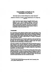
Fig. 1.
TOEFL Curve and Anodic and Cathode Slope
(ΔE / ΔI) Slope is the polarization resistance and βC, βA are the anode and cathode pabet and I corr is the corrosion flow. Using the * relationship, the corrosion rate can be calculated easily. The basic principles of polarization resistance were established by Stern – Geary.
d) The electrochemical impedance method (EIS), electrochemical impedance method is a fast and accurate method for measuring the corrosion rate in certain conditions and is also localized corrosion rates. More than twenty years, the electrochemical impedance technique has been used for corrosion systems. For the first time, Mr. Apel Bowen presented his paper in which the iron - sulfuric acid system was studied stated that in this particular study the mechanism of chemical corrosion is more successful than other methods. One of the important benefits of this approach to other methods, it is possible to use low-amplitude signals. These signals without disrupting the system, could measuring its properties. Another advantage of this method is the possibility of its use in environments with low electrical conductivity. In the study of carbon steel corrosion in neutral water, this method has been used successfully. Principles of EIS technique: If the potential is applied to an electrochemical cell, the current value as output can be used for determining a reaction in progress. In this case, the chemical formation reaction of new chemical particles is draper moving of ions to the electrolyte. Ion motion due to the potential difference occurs and electric current is created. If the applied potential is a sinusoidal, the output signal will be sinusoidal. Interpretation of EIS results: A frequency analyzer connected to the system, allows get and simulation of potential values and flow cell. Using the facilities of the transfer function (FRA), the impedance and admittance is measured directly. As will be explained below, an impedance curve in terms of frequency makes it possible to check all properties of the system. A simple corrosion system with capacitor and parallel resistance and a series resistance, was shown in Figure 2. The results of this equivalent circuit were drawn as Argand diagram. Seri resistance RΩ is relevant to resistance of the electrolyte, the surface film and the connecting wires. Rt Parallel resistance, known as load transfer resistance and is determiner of corrosion rate of reaction. Double layer formed on the surface of the electrolyte can be considered as a capacitor because in this layer, the number of electrical charges on both sides of layer was equal and have different sign. With reducing the frequency, asytans cup will be reduced so that stop flow of current from capacitor and current only passes through Rt. In the near zero frequency, impedance value is function of Rt and RΩ.
ISSN : 2028-9324
Vol. 1 No. 2, Dec. 2012
155
Investigation of Corrosion of the Pipeline Using TOEFLT in Iran Refinery
Fig. 2.
Imaginary Impedance Curves: a Simplified Equivalent Circuit
In practice, this simple model is not enough to determine the reaction and other complex models used to explain the reactions. The equivalent circuit consists of components for the influence of ions and the imaginary component is associated with induction loops. It is clear that by such a curve, the main parameters of Mpl electrical resistance, and impact of duallayer asytans cup in the corrosion reaction by simply changing the frequency range is measured. Frequency range, depending on the nature of the process can vary from 1 to 10 MHZ. Direct measurements of corrosion rates by electrochemical impedance: Despite the many advantages of the EIS method use this method for monitoring corrosion in the field simply is not possible. In this regard there are two fundamental problems: The first problem, the time required to draw a complete diagram of the impedance. The limitation due to the rapidly changing system conditions is of particular importance. The second problem is the interpretation of complex results of EIS. To overcome this problem, there is a way which consists of finding the geometric center of the three-point arc shaped of the imaginary impedance. This method is development of twopoint method provided by Haryana and Tesoro. In this way, at high frequencies, the impedance will be equal to solution resistance RS, and at low frequencies, equal to the sum of solution resistance and polarization resistance (RS+RP). With this new method of analysis, could use this technique that was used previously only in laboratories directly in the field.
3
EVALUATION OF EOR METHOD
EOR method evaluation is performing for petroleum gravity, stone type, and tank humectants and tank localities conditions for liquid injection. When the water inject to the tank the interaction could be performed in different ways, if the is humectants, penetrated water can exit petroleum from tank, which is because of capillary absorption. If the frame is humectants, petroleum exit will perform whenever the pressure is more than threshold; this is controllable by the height of tank block. Experiments and experimental data for recovery capillary absorption are according to data in 1950. Browns coble & Dyse (1952) studied the ability of water absorption in the sandstone lands. It will discuss about technical and economic condition, in the next year, it was performed by many of universities of United States in laboratory. Caspian sea is one of the good case for water injection and row petroleum recovery by capillary absorption, that is because of carbon in the tank`s stone. Row petroleum viscosity, is one of the limitation factor in the tank recovery. High viscosity in the petroleum leads to low recovery. In this article, it was performed many experiments on different stones by dense row petroleum and for comparison between dense petroleum and diluted petroleum on sand stones and lime stones. Whenever diluted and dense petroleum are comparing, lower final recovery of dense petroleum is because of its high incipient factor temperature and low humectants of tank is for coupling of water and dense petroleum. In any case, recovery is usually dependent to the petroleum viscosity. So, first is rapid production and Second point is increasing of find recovery. In this condition, it is evaluating the interaction between water phase and hemi cylindrical frame, and as we observe, recovery velocity and final recovery of dense petroleum is limited.
4
CHEMICAL MATTERS LEAD TO EOR
Polymer: Before these experiments, polymeric solution injection as aqueous phase was performed for tank petroleum recovery in the laboratorial condition, for diluted, petroleum. The only case about polymeric solution injection that leads to the high recovery was in the river basin in Vioming (2000). In this study, for both sandstone and limestone, the polymeric matter was as an aqueous phase. The results were shown in the figure 2, about injection on dense petroleum with ISSN : 2028-9324
Vol. 1 No. 2, Dec. 2012
156
Amir Samimi and Soroush Zarinabadi
sandstone. One of the limitation factors in this method is: it is necessary to use very dense polymeric, for high viscous petroleum, clay increases the surface absorption of polymer will have good results, when the polymer injection begins before increasing the relation between water to petroleum. Polymeric solution injection leads to increasing of recovery velocity. But final recovery is not affected by adding polymeric solution. Fluids characters are noted in table pay attention that polymer injection leads to decrease of IFT. Everyone can see polymeric solution effects on dense petroleum recovery for limestone. Dense petroleum reaction is the same as limestone, without taking into that polymeric matter injected to the dense petroleum. When limestone and sandstone diluted petroleum are comparing with each other, evaluating of absorption effect become more logical. It expected that, because of higher surface absorption of polymeric matter on limestone than sandstone, recovery results decrease.
5
GAS INJECTION
It is able to inject gases into the pit as a gas phase. Gas phase is usually as a phase that leads to high recovery of pit, whenever, we have gas oil gravity drainage, that because of different gravity between fluids in the breaking point of mold and in the mold. This process will decrease the recovery than other mechanism, especially about dense oil, and it can lead to high recovery by heat and mixed gases injection. Many studied had performed on oil recovery from pit by mixed gases. They use Nitrogen gas for breaking tank because of it is available and cheap. If the mixed condition exits, it can increase the oil recovery of the tank. Methane is another gas that is used for this purpose. Morel et al. observed that oil recovery by methane is twice of nitrogen. Lately, Lenormand et al., purposed transfer subsidiary for diffusion between tank and breakage, in these studies diluted oil is used as a typical from in the oil tank. CO2 injection is one of the most available ways about non-hydro carbonic gases that release industry about natural gas injection for grazing, CO2 gas can exits diluted and medium components from oil, and if the pressure is high, it can exits oil from the tank by more mixing, so the viscosity become lower and oil turgid. This method is very valuable for dense oil with varicose type of solvents. In the current study, an experiment for increasing the recovery of pit by saluted gases was performed. So, part of this study is experimental. It is important to note that, availability to mixed methane and nitrogen with dense oil is so difficult, and we can use another solvent for that, and it is not economical, but it is successful way for technical aspect. Whenever, there is low humectant and permeability, the only substitute for heating method in the carbonate tank or tanks with dense oil is, saluted gas injection (CO2), and the oil recovery increase. CO2 limitations are: very low viscosity for CO2, leads to low control on movement, so quick separation become difficult and other problems and limitation.
6
NITROGEN INJECTION
Nitrogen or combustion gas means: high injection of nitrogen, or other gases into the tank that it can mix with each other according to the pressure and it`s components. This method is used for diluted oil recovery that is able to absorbed added gas into the tank. This condition is low methane and at least 5000 feet depth that leads to resistant of rock tank on high pressure of injection, and it wouldn`t break. When nitrogen injects into the tank, we will have mixture phase, that`s because of light component evaporation. It forms a mixture or solution phase, by its movement from injection phase to the tank. Continuous injection leads to oil mass movement into the production pits. It is able to use water injection, alternatively, for higher recovery and high buoyancy index for oil. Nitrogen advantage that is, it doesn`t have corrosive effect. Because of its price that is cheap, we will have more injection. Nitrogen injection is usually after the carbonic. Gas or mixed hydro carbons. This method`s limitations are: mixing will performed in the diluted oil and high pressure, so it`s necessary to be more depth, slope excavation is suitable for decreasing unsuitable movement, that`s because it allows gravity to control movement.
7
EOR EXPLOITATION
In the EOR project: remains oil determinations in the tank, necessary mechanisms for better exploitation and in-use equipment are important factors, generally, if the purpose is to exit tank oil completely, it`s important to pay attention to the final recovery, but if the purpose is high production, it`s important to focus on the increasing recovery velocity methods, than final recovery. The best candidates for this strategy are low recovery factors (dense oil carbonates). Final recovery and its velocity are practical factors of recovery in this article. Following the experimental methods is not suitable for total expense analyze. That`s because of I statics nature of this method, but in reality, continuous injection in the abuse phase is possible. Understanding the injection velocity and it`s density is one way for determining method`s expense and chemical matter that`s necessary for injection and final recovery. It`s necessary to perform exact experiments in laboratories for determining Fluid`s amount for final recovery. This fact determines how the method is effective, and finally it leads to determine project expense. Beaver et al. performed exact analyze for determining exploitation amount of chemical matters injection in to the ISSN : 2028-9324
Vol. 1 No. 2, Dec. 2012
157
Investigation of Corrosion of the Pipeline Using TOEFLT in Iran Refinery
homogeneous samples, they performed various experiments according to the absorption and salty water effects and analyzing different ways for chemical injection, for determining the best way. Results were useful in the same forms (breaking systems), but there`s no report about chemical injection into the breakage tanks, until now. Useful numerical and experimental studies were performed for fluid flow in the breakage environments. Expenses analyze for water injection, are an important factor because of low expense for its injection, and were performed studies about numerical dramatis tic to determine optimistic velocity of vapor injection for different tanks, according to breakage and days. Both two studies showed that, injection velocity is depending on tank type and penetration and its thermal capacity. In these studies, chemical absorption (especially for carbonate rocks), critical density (for chemical matters or gas injection), or thermal degree (hot water) were taken into consideration for optimize process.
8
CONCLUSION
In this study we studied EOR methods for dense oil recovery from mold in the breakage tanks. Analyze and comparison of recovery with capillarity of salty water, polymeric solution and hot water on different sample of rocks showed high recovery of dense row oil in the EOR methods, and it is more detected in the diluted row oil. Oil (diluted) can recover by water injection in the sand stone condition and with chemical matter and thermal methods. Hot water recovery is more rapid and higher than chemical recovery. For higher recovery of sand stone, hot water has higher and more rapid recovery than gas injection, polymeric matter can increase recovery velocity, but finally its recovery is as the same as salty water. Because of thermal breakage, hot water has the most rapid recovery of dense row oil for oil-wet carbonate. So, it`s possible to use hot water injection instead of mixed gas injection. To final exploiting, hot water degree and process optimize is technical and economical. Berea sand stone and Indiana lime stone were used as rock samples. They were cut in 2.5cm diameter and 7.5cm length from blocks and they have medium value in porosity and penetration is 17% and 8.5cm for lime stone. Each sample was examined once to avoid error. Experiments were performed in the statistical condition with oil injection, in the 100% saturated condition, and recovery than time, until when there is no oil from sample. In oil and gas industries, corrosion monitoring was carrying out with different methods. In our country, corrosion coupons are typically used. While the growth of technology, suggests use of the probe. Probes, especially the electrochemical probes have the faster and more accurately results. Also EIS probes can help to extract the details of local corrosion. It is not possible with other monitoring methods. In this paper, only the monitoring methods and electrochemical techniques were introduced. Details of each of the techniques, described in used sources.
REFERENCES [1] E. Eriksrud and T. Sonlvedt, “Advances in CO2 Corrosion,” NACE pub, Houston, vol. 1, 1984. [2] Hibbert, D.B and James, A.M, “Dictionary of Electrochemistry,” Macmillan Press, Second Edition, London, pp. 87-90, 1984. [3] Loto, C.A and Okusanya, “The influence of clay addition on the electrochemical corrosion behavior of mild steel,” in Concrete Journal of Corrosion Prevention and Control, vol. 36, no. 6, pp. 103-109, 1989. [4] Trevor, J. “More than 250 feared dead in Nigeria pipeline explosion WSWS,” News and Analysis Africa, 2005. [5] Rolf, N, “Corrosion control in soil and gas pipelines,” Journal of Exploration and production – the oil and gas review, vol. 2, pp. 20-23, 2003. [6] T.C. Chevro and M. Bonis, “Use of pH Stablization of Corrosion Control of Long Multiphase Pipelines”, TOTAL FINA ELF, Second Congress of Corrosion in Oil Industries, Iran, Oil Industry University. [7] A. Nazarboland and S. Java poor, “Application of corrosion technology into gas and oil pipe,” Second National Conference Conference of Technology in Oil Craft / Challenges and Strategies. [8] Samimi, Amir and Zarinabadi, Soroush, “An Analysis of Polyethylene Coating Corrosion in Oil and Gas Pipelines,” Journal of American Science, U.S.A., 2011. [9] Zarinabadi, Soroush and Samimi, Amir, “Scrutiny Water Penetration in Three-layer Polyethylene Coverage,” Journal of American Science, U.S.A., 2011. [10] Samimi, Amir and Zarinabadi, Soroush, “Reduction of greenhouse gases emission and effect on environment,” Australian Journal of Basic and Applied Science, pp. 752-756, 2011. [11] Zarinabadi, Soroush and Samimi, Amir, “Problems of hydrate formation in oil and gas pipes deal,” Australian Journal of Basic and Applied Science, 2011. [12] Zarinabadi, Soroush, Samimi, Amir, Erfan Ziarifar, and Mohammad Sadegh Marouf, “Modeling and Simulation for Olefin Production in Amir Kabir Petrochemical,” Proceedings of the World Congress on Engineering and Computer Science, 2010, Vol II, WCECS, San Francisco, USA, 2010.
ISSN : 2028-9324
Vol. 1 No. 2, Dec. 2012
158
Amir Samimi and Soroush Zarinabadi
[13] Samimi, Amir and Zarinabadi, Soroush, “Application Polyurethane as Coating in Oil and Gas Pipelines,” International Journal of Science and Investigations, France, pp. 43-45, 2012. [14] Samimi, Amir, Zarinabadi, Soroush, and Samimi, Marzieh, “Solar Energy Application on Environmental Protection,” International Journal of Science and Investigations, France, pp. 21-24, 2012. [15] Setoudeh, Mehrdad, Samimi, Amir, Zarinabadi, Soroush, Almasinia, Babak, Nazem, Esmaeil, Rezaei, Rohollah, and hedayati, Abbas, “Experimental Study of Factors Affecting Corrosion in Gas Wells Using Potantio Acetate and Galvan Acetate Tests,” International Journal of Science and Investigations, pp. 13-16, 2012. [16] Samimi, Amir, “Preventing Hydrate Formation in Gas Transporting Pipe Lines with Synthetic Inhibitors,” International Journal of Science and Investigations, France, pp. 48-50, 2012. [17] Rice, W., “Hydrogen Production from Methane Hydrate with Sequestering of Carbon Dioxide,” International Journal of Hydrogen Energy, 2006. [18] Samimi, Amir, Zarinabadi, Soroush, Setoudeh, Mehrdad, and Safavian, Amir, “Review Applications to Prevent Corrosion Reducing Gas Pipe Line,” International Journal of Basic and Applied science, Indonesia, pp. 423-428, 2012. [19] Samimi, Amir, Zarinabadi, Soroush, and Setoudeh, Mehrdad, “Safety and Inspection for Preventing Fouling in Oil Exchangers,” International Journal of Basic and Applied science, Indonesia, pp. 429-434, 2012. [20] Samimi, Amir and Zarinabadi, Soroush, “The Comparison of Increasing Method for Petroleum Pits Output (Fluids Dynamic),” International Journal of Basic and Applied science, Indonesia, pp. 435-439, 2012. [21] Samimi, Amir, Almasinia, Babak, Nazem, Esmaeil, Rezaei, Rohollah, Hedayati, Abbas, and Afkhami, Mahbobeh, “Investigating MIDEA Corrosion Treatment on Carbonic Simple Steel in Amin Unit of Isfahan Refinery,” Solar Energy Application on Environmental Protection, International Journal of Science and Investigations, France, 2012. [22] Samimi, Amir, “Investigation Results of Properties of Stripe Coatings in Oil and Gas Pipelines,” International Journal of Science and Investigations, France, 2012. [23] Samimi, Amir, “Studying Corrosion Electrochemical Mechanism in Tube Line and Gas Wells,” International Journal of Science and Investigations, France, 2012.
Amir Samimi (16/05/1983, Isfahan City, Isfahan Province, Iran) Studied M.SC Chemical Engineering, Master at Islamic Azad University, The Member of IAENG, Have 2 Years Experience in Oil Refinery Company, Member of Young Research, and Have 17 Articles in the International Journal, Conference (U.S.A, France, Italy, Indonesia, India, Australia, Europe Chemical Engineering Conference) and More than 45 Articles in the National Journal, Conference in Iran. Email:
[email protected]
ISSN : 2028-9324
Vol. 1 No. 2, Dec. 2012
159