molecules Article
iPPBS-Opt: A Sequence-Based Ensemble Classifier for Identifying Protein-Protein Binding Sites by Optimizing Imbalanced Training Datasets Jianhua Jia 1,2, *, Zi Liu 1 , Xuan Xiao 1,2, *, Bingxiang Liu 1 and Kuo-Chen Chou 2,3 Received: 18 November 2015 ; Accepted: 7 January 2016 ; Published: 19 January 2016 Academic Editor: Derek J. McPhee 1 2 3
*
Computer Department, Jing-De-Zhen Ceramic Institute, Jing-De-Zhen 333403, China;
[email protected] (Z.L.);
[email protected] (B.L.) Gordon Life Science Institute, Boston, MA 02478, USA;
[email protected] Center of Excellence in Genomic Medicine Research (CEGMR), King Abdulaziz University, Jeddah 21589, Saudi Arabia Correspondence:
[email protected] (J.J.);
[email protected] (X.X.); Tel.: +86-1397-9866-529 (J.J.); +86-1387-9809-729 (X.X.)
Abstract: Knowledge of protein-protein interactions and their binding sites is indispensable for in-depth understanding of the networks in living cells. With the avalanche of protein sequences generated in the postgenomic age, it is critical to develop computational methods for identifying in a timely fashion the protein-protein binding sites (PPBSs) based on the sequence information alone because the information obtained by this way can be used for both biomedical research and drug development. To address such a challenge, we have proposed a new predictor, called iPPBS-Opt, in which we have used: (1) the K-Nearest Neighbors Cleaning (KNNC) and Inserting Hypothetical Training Samples (IHTS) treatments to optimize the training dataset; (2) the ensemble voting approach to select the most relevant features; and (3) the stationary wavelet transform to formulate the statistical samples. Cross-validation tests by targeting the experiment-confirmed results have demonstrated that the new predictor is very promising, implying that the aforementioned practices are indeed very effective. Particularly, the approach of using the wavelets to express protein/peptide sequences might be the key in grasping the problem’s essence, fully consistent with the findings that many important biological functions of proteins can be elucidated with their low-frequency internal motions. To maximize the convenience of most experimental scientists, we have provided a step-by-step guide on how to use the predictor’s web server (http://www.jci-bioinfo.cn/iPPBS-Opt) to get the desired results without the need to go through the complicated mathematical equations involved. Keywords: protein-protein binding sites; physicochemical property; stationary wavelet transform; PseAAC; Optimize training dataset; KNNC; IHTS; target cross-validation
1. Introduction Individual proteins rarely function alone. Most proteins whose functions are essential to life are associated with protein-protein interactions [1]. Actually, these kinds of interactions affect the biological processes in a living cell. To really understand protein-protein interactions, however, it is indispensable to acquire the information of protein-protein binding site (PPBS). Despite many studies on the binding site of a protein or DNA with its ligand (small molecule) have been made [2–8], relatively much less studies have been conducted on PPBS, particularly based on the sequence information alone. It is both time-consuming and expensive to determine PPBS purely based on biochemical experiments. Facing the enormous number of protein sequences generated in the postgenomic era, it is highly
Molecules 2016, 21, 95; doi:10.3390/molecules21010095
www.mdpi.com/journal/molecules
Molecules 2016, 21, 95
2 of 19
desired to develop computational methods to identify PPBSs for uncharacterized proteins so that they can be timely used for both basic research and drug development, such as conducting mutagenesis studies [9] and prioritize drug targets. Given a protein sequence, how can one identify which of its constituent amino acid residues are located in the binding sites? Actually, considerable efforts were made to address this problem [10,11]. Although the aforementioned works each have their own merits and did play a role in stimulating the development of this area, further work is needed due to the following shortcomings: (1) The datasets used by these authors to train their prediction methods were highly imbalanced or with a strong bias; i.e., the number of non-PPBS samples was significantly larger than that of PPBS samples; (2) None of their prediction methods has a publicly accessible web server, and hence their practical application value is quite limited, particularly for the majority of experimental scientists. The present study is initiated in an attempt to develop a new PPBS predictor by addressing the aforementioned shortcomings. According to the Chou’s 5-step rule [12] and the demonstrations in a series of recent publications [13–20], to establish a really useful sequence-based statistical predictor for a biological system, we should make the following five aspects crystal clear: (1) how to construct or select a valid benchmark dataset to train and test the predictor; (2) how to formulate the biological sequence samples with an effective mathematical expression that can truly reflect their intrinsic correlation with the target to be predicted; (3) how to introduce or develop a powerful algorithm (or engine) to operate the prediction; (4) how to properly perform cross-validation tests to objectively evaluate its anticipated accuracy; (5) how to establish a user-friendly web-server that is accessible to the public. Below, we are to address the five procedures one-by-one. 2. Materials and Methods 2.1. Benchmark Dataset Two benchmark datasets were used for the current study. One is the “surface-residue” dataset and the other is “all-residue” dataset, as described below. The protein-protein interfaces are usually formed by those residues, which are exposed to the solvent after the two counterparts are separated from each other [21]. Given a protein sample with L residues as expressed by: P “ R1 R2 R3 R4 R5 R6 R7 ¨ ¨ ¨ R L
(1)
where R1 represents the 1st amino acid residue of the protein P, R2 the 2nd residue, and so forth. The residue Ri pi “ 1, 2, ¨ ¨ ¨ , Lq is deemed as a surface residue if it satisfies the following condition: φ pRi q “
ASApRi |Pq ą 25% ASA pRi q
(2)
where ASA(Ri |P) is the accessible surface area of Ri when it is a part of protein P, ASA(Ri ) is the accessible surface area of the free Ri that is actually its maximal accessible surface area as given in Table 1 [22], and φ pRi q is the ratio of the two. Table 1. Maximum accessible surface area (ASA) of different amino acids a .
a
AA
A
B
C
D
E
F
G
H
I
K
L
M
MaxASA AA MaxASA
106 N 157
160 P 136
135 Q 198
163 R 248
194 S 130
197 T 142
84 V 142
184 W 227
169 X 180
205 Y 222
164 Z 196
188
Amino acids are represented by their one-letter codes. Here, B stands for D or N; Z for E or Q, and X for an undetermined amino acid.
2015, xx
Algorithms Algorithms 2015, Algorithms xx 2015, xx 2015, xx
2
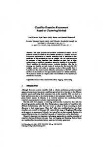
2 Algorithms 2015, xx clutters.clutters. In recent clutters. In years, recent Inayears, recent seriesayears, of series simple aofseries simple and of fastsimple and algorithm fastand algorithm fast based algorithm on based fourier on based fourier transform on fourier transform wastransform proposed, was propo wa Molecules 2016, 21, 95 3 of 19 Algorithms 2015, xx 2 such assuch spectral assuch spectral residual(SR) asalgorithm spectral residual(SR) [5], residual(SR) phase [5], spectrum phase [5],spectrum phase of fourier spectrum of fourier transform(PFT) of fourier transform(PFT) transform(PFT) [6], hypercomplex [6], hypercomplex [6], hypercomp fourier fou ecent years, a series of simple and fast based on fourier transform was proposed, transform(HFT) transform(HFT) transform(HFT) [7].ofWith [7].regards With [7]. to With small regards totarget small detection, target smallof detection, target frequency detection, frequency domain frequency domain method domain method is quite is different quiteistrans diffe qui clutters. Inregards recent years, ato series simple and fast algorithm based onmethod fourier tral residual(SR) [5], phase spectrum fourier transform(PFT) hypercomplex fourier Furthermore, the surface residue Ri is deemed as[6], interfacial residue [23] if: clutters. In recent years, a methods. series of simple andairspace fast algorithm onthe fourier transform was proposed, from from methods. other from methods. other Itsuch transforms Itfrequency transforms It transforms airspace the information the airspace information tobased information the frequency to frequency to fourier the domain, frequency domain, defines domain, defines significant defines signifi as spectral residual(SR) [5], spectrum of transform(PFT) [6],2hy Algorithms Algorithms 2015, Algorithms 2015, xx xx 2015, xx the FT) [7]. With regards toother small target detection, domain method isphase quite different 2 ˚ such as spectral residual(SR) [5], phase spectrum of fourier transform(PFT) [6], hypercomplex fourier pR |Pq ´ ASA pR |PPq ą 1 ASA A (3) i frequency i regards target and target tests and target intests the and frequency intests the frequency in the domain. domain. While, domain. While, spectralWhile, spectral residual (SR)detection, residual approach (SR) approach (SR) doesapproach not does rely not on does rely the not on transform(HFT) [7]. With toresidual smallspectral target frequency domain meth methods. 2015, xx It transforms the airspace information to the frequency domain, defines significant 2 transform(HFT) [7]. With regards to small target detection, frequency domain method is quite different parameters. parameters. ItAlgorithms parameters. calculates Itspectral calculates the It residual difference calculates themethods. difference the between difference between the original between the original signal the original and signal a smooth and signal a smooth one and athe smooth the one log in the amplitude onelog in the ampli log from other Itand the airspace information toin frequency 2015, xx ests in the frequency domain. While, approach does not rely on the where ASA(R is accessible surface area of Ritransforms when it is aand part of protein-protein complex. clutters. clutters. In recent clutters. Inthe recent years, In recent years, a series ayears, series of (SR) simple a of series simple of fast simple and algorithm fast algorithm fast based algorithm based on fourier on based fourier transform on fourier transform was transform proposed, wasdomain propo was i |PP) from other methods. Itwe transforms thea program airspace information toSR theits domain, defines significant spectrum, spectrum, spectrum, then and makes then and up makes then aand saliency up makes saliency map aby saliency map transforming byfind map transforming by transforming tofrequency spatial SR to spectral spatial domain. SR to domain. spatial PFT approach domain. PFT PFT detects appro det Algorithms 2015, xxand 2approach target tests in the frequency domain. residual (SR) approach For aas given protein, can use DSSP [24] to out all surface residues It calculates the difference between the signal and aup smooth one the log amplitude such such spectral as such spectral residual(SR) asoriginal spectral residual(SR) residual(SR) [5], phase [5], phase spectrum [5], spectrum phase ofinspectrum fourier of fourier transform(PFT) ofWhile, fourier transform(PFT) transform(PFT) [6],based hypercomplex [6],onhypercomplex [6], hypercomp fourierfod ecent years, a series of simple and fast algorithm based on fourier transform was proposed, target tests in PSAIA the frequency domain. While, spectral (SR) approach does not rely on Equation (2), andtargets use program [25] tothat find all its interfacial residues based on Equation (3).the small and targets small from small the targets from reconstruction the from reconstruction theItspatial reconstruction is calculated that is calculated thatonly isresidual calculated by only the by phase only the spectrum phase by thespectrum phase of spectrum input of signal. input ofthethe sig in parameters. the difference between the original signal a the smooth one nd then makes up a saliency map clutters. by transforming SR to domain. PFT approach detects transform(HFT) transform(HFT) [7]. With [7]. regards With [7]. regards With tocalculates small regards to small target to target detection, small detection, target frequency detection, frequency domain frequency domain method domain method isand quite method is different quiteisdiffe qui In recent years, aas series of simple and fast algorithm based on fourier transform was tral residual(SR) parameters. [5], spectrum of fourier transform(PFT) [6], hypercomplex fourier Ifphase onlytransform(HFT) considering the surface residues done in [26] for the 99 polypeptide chains extracted by It calculates the difference between the original signal and a smooth one in the log amplitude It omits It the omits computation Itthe computation the ofcomputation SR in of the SR amplitude in ofmakes the SR amplitude in up the spectrum, amplitude spectrum, which spectrum, saves which about saves which1/3 about saves computational 1/3 about computational 1/3domain. computa cost. Pc spectrum, and then aairspace saliency map by transforming SR to spatial In recent years, aomits series oftransforms simple and fast algorithm based on fourier transform was proposed, s from theclutters. reconstruction that is calculated only by the phase spectrum of the input signal. from other from methods. other from methods. other It methods. Itfrequency transforms Itthe transforms airspace the airspace the information information to information the to frequency the frequency to the domain, frequency defines domain, defines significant defines signifi such as spectral residual(SR) [5], phase spectrum of fourier transform(PFT) [6], hypercompl Deng et [10] from the 54 heterocomplexes in the Protein Data we have obtained the domain, results FT) [7]. With regards toal.small target detection, domain method isBank, quite different spectrum, and then makes up a saliency map by transforming SR to spatial domain. PFT approach detects HFT approach HFT approach HFT explains approach explains the intrinsic explains the intrinsic theory the of intrinsic of theory saliency of theory saliency detector of saliency detector in is thecalculated detector frequency in the frequency inonly domain the frequency domain andphase use domain and spectral useand speu small targets from the reconstruction that by the spectrum suchofasthat spectral residual(SR) [5], phase spectrum fourier transform(PFT) [6], hypercomplex fourier can be formulated as follows: computation SR in the amplitude spectrum, which saves about 1/3 computational cost. target target and tests and target in tests the andinfrequency tests theto[7]. frequency inthe the domain. frequency domain. While, domain. spectral While, spectral residual spectral residual (SR)residual approach (SR) approach (SR) does approach not does rely not does on rely noton transform(HFT) With regards to While, small target detection, frequency domain method is the quit ď methods. It transforms the airspace information frequency domain, defines significant ` ´ small from the reconstruction that issurf calculated only byamplitude the phasespectrum, spectrum which of the signal. filter targets to filter suppress to filter suppress repeated to suppress repeated patterns.S repeated (4) input “patterns.S Itdetector omits the computation of SR inand the saves about 1/3 surffrequency surf transform(HFT) [7]. With regards to small target detection, frequency domain method quite different ch explains the intrinsic theory of saliency inpatterns.S the domain use spectral parameters. parameters. It parameters. calculates It calculates the It residual calculates difference the difference the between difference between the original between the original signal the original signal and a to smooth and signal and oneain smooth one thedomain, in logthe one amplitude log indefines the ampli log from other methods. It transforms the airspace information theaissmooth frequency sts in the frequency domain. While, spectral (SR) approach does not rely on the It omits the computation of SR in the amplitude spectrum, which saves about 1/3 computational cost. Although Although numerous Although numerous methods numerous methods have methods been have proposed, been have proposed, been many proposed, of many them of many may them fail of may them in certain fail may in certain fail circumstances, in certain circumstan circ HFT approach explains the intrinsic theory of saliency detector in the frequency dom frompatterns.S other methods. Ittarget transforms the airspace information to map the domain, defines significant ress repeated where is called the “surface-residue dataset” contains afrequency total of 13,771 surfaces of spectrum, and spectrum, then and makes then and makes up then a the saliency makes upand a saliency map a that saliency by map transforming transforming by transforming SR to SR spatial to spatial SR domain. toresidues, spatial domain. PFT domain. approach PFT approach PFT detects appro surfspectrum, and tests in frequency domain. While, spectral residual (SR) approach does notder It calculates the difference between the original signal aup smooth onebyin the log amplitude ` HFT approach explains the intrinsic theory ofcommon saliency detector in the frequency domain andsituation, use spectral e.g., ground-sky e.g., ground-sky e.g., background ground-sky background [8], background which [8], is which [8], is which common in is the common helicopter in the helicopter in the view. helicopter In view. this In situation, view. this In this targets situation, targets are filter to suppress repeated patterns.S which 2828 are interfacial residues belonging to the positive subset while 10,943 are non-interfacial target and small tests the proposed, frequency domain. While, spectral residual (SR) approach does notspectrum surf numerous methods have in been many of them may fail in is certain circumstances, small targets targets small from targets the from reconstruction from reconstruction the reconstruction that isthat calculated that calculated isonly calculated by only the by phase only the by phase spectrum the phase of on spectrum thethe of input theinof input signal. sig in Ť Itthe calculates the difference between the original signal and arely smooth one thethe log d then makes up residues afilter saliency map parameters. by transforming SR to ´spatial domain. PFT approach detects tobelonging suppress repeated patterns.S , and is the symbol of union in the set theory. the negative subset surf easily mixed easily up mixed easily with up mixed the with background up the with background the clutters background clutters in size clutters in and size easily in and size overlapped easily and overlapped easily by overlapped vegetation, by vegetation, by roads, vegetation, rivers, roads, riv ro Although numerous methods have been proposed, many of them may fail in ce parameters. It calculates the difference between the original signal and a smooth one in the log amplitude -sky background [8],It which is common inthe thecomputation helicopter view. Inamplitude situation, targets are SR It omits the computation It the omits of SR of in SR the of inamplitude SR inthis thespectrum, amplitude spectrum, which spectrum, which saves which saves about about 1/3 saves computational 1/3 about computational 1/3 computa cost. spectrum, and then makes up athe saliency map by transforming to spatial domain. PFT approa s from the reconstruction that isnumerous calculated only bydone the phase spectrum ofcorresponding the input signal. If omits considering all thecomputation residues as in [11], however, the benchmark dataset can Although methods have been proposed, many of them may fail in certain circumstances, bridges bridges [9], resulting bridges [9], resulting a [9], huge resulting a false huge rate a false huge in traditional rate false in traditional rate algorithm. in traditional algorithm. algorithm. e.g., ground-sky background [8], which is common in the helicopter view. In this and then makes up a saliency map by transforming SR to spatial domain. PFT approach detects d up with spectrum, the background clutters inexplains size andthe easily overlapped bysaliency vegetation, roads, HFT HFT HFT approach explains intrinsic explains the intrinsic theory the intrinsic theory of theory of saliency detector of saliency detector in rivers, the detector in frequency the in the domain frequency domain and use domain and spectral and spe us small targets from the reconstruction that is calculated only byfrequency the phase spectrum ofuse the inp expressed by:approach computation of be SR in ground-sky theapproach amplitude spectrum, which saves about 1/3 computational cost. e.g., background [8], which is common in the helicopter view. In this situation, targets are ď In order In toorder design Intoorder design an appropriate to that design an appropriate anmethod, appropriate method, a background small method, athe target small adetection target small detection target method detection method inspired inspired by the inspired by human thevege by hu easily mixed up with clutters in size and easily overlapped by `the ´ by from the is calculated only phase spectrum of the inputmethod signal. resulting asmall hugetargets falsefilter rate insuppress traditional to filter to filter suppress repeated toalgorithm. suppress repeated patterns.S repeated patterns.S patterns.S (5) Itreconstruction omits the computation of“ SR spectrum, which saves about 1/3 computat allfrequency all in the all amplitude ch explains the intrinsic theory of saliency detector in the domain and use spectral easily mixed up with system the background clutters inhuge and overlapped by vegetation, roads, rivers, visual system visual system (HVS) visual (HVS) has been (HVS) has designed been has designed been inspectrum, this paper. insize this HVS paper. in easily this isHVS paper. athe kind isHVS of a kind layered isalgorithm. of a kind layered image of layered processing image processing image system process sys bridges [9], resulting adesigned false rate in the computation SR intarget the amplitude which saves about 1/3 computational cost. to design Itanomits appropriate method, aof small detection method inspired by human Although Although numerous Although numerous methods numerous methods have methods been have proposed, been have proposed, beenmany proposed, many oftraditional them of many may them of fail may them infail certain may inare fail certain circumstances, in certain circumstan circ HFT approach explains the intrinsic theory of saliency detector in the frequency domain and u ress repeated patterns.S where is called the “all-residue dataset” that contains a total of 27,442 residues, of which 2828 all [9], resulting a huge false rate in traditional algorithm. bridges consisting consisting of optical consisting of optical system, of optical system, retina system, and retina visual and retina pathways, visual and pathways, visual which pathways, is which nonuniform is which nonuniform is and nonuniform nonlinear. and nonlinear. and The nonlinear. rest The of re In order to design an appropriate method, a small target detection method ins ` HFT approach explains the intrinsic theory of saliency detector in the frequency domain and use spectral m (HVS) has been designed in this paper. HVS a[8], kind ofpatterns.S layered image processing system e.g., ground-sky e.g., ground-sky e.g., background ground-sky background background which [8], which is[8], common which isallcommon in is the common in helicopter the helicopter innon-interfacial theview. helicopter view. In this In view. situation, this In situation, this targets situation, targets are filter to suppress repeated interfacial residues belonging toisthe positive subset while 24,614 are residues numerous methods have been proposed, many of them may fail certain circumstances, In order to design anvisual appropriate method, a2,in small target detection method inspired byof the human ´ this paper this is paper organized this is paper organized as is follows. organized as follows. In as Section follows. In Section we In Section describe 2, we describe 2, the we framework describe the framework the of framework the proposed of the proposed of algorithm the proposed algori system (HVS) has been designed in this paper. HVS is a kind layered imag filter tobelonging suppress repeated patterns.S the negative subset .the f optical system, retina andeasily visual pathways, which is nonuniform and nonlinear. The rest of all easily mixed mixed easily up with mixed up with background up with background the clutters background clutters in size clutters inand size easily in and size easily overlapped and overlapped easily by overlapped vegetation, by vegetation, roads, vegetation, roads, rivers, ro riv Although methods have been proposed, many of them may failbyin certain circu -sky background [8], which is common inthe thenumerous helicopter view. In this situation, targets are visual system (HVS) has been designed inwe this paper. HVS is a experimental kind ofresults. layered image processing For readers’ convenience, given in S1 Dataset (List of the 99 proteins and their residues’ for small for target small for detection. target small detection. target In Section detection. In Section 3, In Section present 3, we present the 3, we experimental present the the experimental results. Section results. Section 4isisnonuniform the Section 4conclusion is system the4conclu is the consisting of optical system, retina and visual pathways, which and n numerous methods have been proposed, many of them may fail in certain circumstances, organized asAlthough follows. In Section 2, we describe the framework of the proposed algorithm bridges bridges [9], e.g., resulting bridges [9],size resulting [9], a huge resulting a false huge rate afalse huge inrate traditional false inwhich rate traditional inalgorithm. algorithm. algorithm. ground-sky background [8], istraditional common in the helicopter view. In this situation, d up with the background clutters in and easily overlapped by vegetation, roads, rivers, attributions associated thepaper protein-protein siteswhich is In in Section Supplementary Materials) is framework a The rest of consisting of optical system, retina and visualbinding pathways, is nonuniform and nonlinear. of of this 3, article. ofbackground this article. of thiswith article. this iscommon organized asafollows. 2, we describe the e.g., In ground-sky [8], which inmethod, the helicopter view. In detection this situation, targets are get detection. Section we present the experimental Section 4a issmall the conclusion In order In order to two design In to order design an to appropriate design anis appropriate anresults. method, appropriate small method, target asize target small detection target method detection method inspired method inspired the inspired byhuman thethe by hu easily mixed up with the background clutters inin and easily overlapped byby vegetation, roa combination of the benchmark datasets, where those labeled column 3 are all the residues resulting a huge false rate in traditional algorithm. thisxx paper is organized as follows. In Section 2, we describe the framework ofexperimental the proposed algorithm Algorithms 2015, Algorithms 2015, xx 2 for small target detection. In Section 3, we present the results. Section easily mixed up visual with the background clutters indesigned size and easily overlapped by vegetation, roads, rivers, e. determined by experiments, those indetection column 4 method are of rate surface and non-surface residues, and in image visual system system visual (HVS) system (HVS) has been (HVS) has designed been been in this designed inpaper. this paper. HVS this paper. HVS a kind is HVS aof kind layered is aofkind layered image ofthose layered image processing processing system process sy bridges [9], resulting ahas huge false in in traditional algorithm. to design an appropriate method, aAlgorithm small target inspired byis the human for small target detection. In Section 3, we present the experimental results. Section 4 is the conclusion 2. Algorithm 2. Algorithm 2. Based Based on Human on Based Human Visual on Human Visual System Visual System System of this article. 5 are of of and non-interface residues. bridgescolumn [9],consisting resulting ainterface huge false rate in traditional algorithm. consisting consisting optical optical system, of system, system, retina and visual and retina visual pathways, and pathways, visual which pathways, which issystem nonuniform which is nonuniform is and nonuniform nonlinear. and nonlinear. and The nonlinear. rest The ofret Inoforder to optical design an method, a small target detection method inspired by m (HVS) has beenof designed in this paper. HVS is retina a kind ofappropriate layered image processing this article. As pointed out in a comprehensive review [27] there is no need to method separate ainspired benchmark dataset clutters. years, a series clutters. of simple In recent and years, fast algorithm a series of based simple on and fourier fast transform algorithm was based proposed, on fourier transform was Algorithms 2015, xx m Based on In Human Visual System In recent orderthis to paper design an appropriate method, small target detection by the human this paper isvisual this organized is paper organized is aswhich organized follows. as follows. In as Section follows. In Section 2,Inwe Section describe we paper. describe 2,The we thearest describe framework the offramework thelayered of proposed the proposed of the algorithm proposed algor system (HVS) has been designed in2, this HVS isframework a the kind of image processi f optical system, into retina and visual pathways, is nonuniform and nonlinear. of a training dataset and aoftesting dataset for examining the quality of prediction method if it is 2.1. Framework 2.1. Framework 2.1. of Framework the Proposed the Proposed of Two the Proposed Stage Two Algorithm—A Stage Two Algorithm—A Stage Algorithm—A Brief Description Brief Description Brief Description 2. Algorithm Based on Human Visual System such asvisual spectral residual(SR) such [5], as phase spectral spectrum residual(SR) of fourier [5], transform(PFT) phase spectrum [6], of hypercomplex fourier transform(PFT) fourier [6], hypercompl system (HVS) has been designed in this paper. HVS ispresent kind of layered image processing forbyIn small for small target for2, target detection. small target Indetection. Section In Section 3,Inwe Section 3, present we 3,avisual the we experimental present the the experimental results. results. results. Section 4 system is the Section 4 is conclusion the4conclu is theT consisting of optical system, retina and pathways, isSection nonuniform and nonlinear. tested the jackknife test ordetection. subsampling (K-fold) cross-validation testexperimental because the outcome obtained organized as follows. Section we the framework of the proposed algorithm 15, xx 2which 2. Algorithm Based ondescribe Human Visual System transform(HFT) [7]. With regards transform(HFT) to small target [7]. With detection, regards frequency to small domain target detection, method is frequency quite different domain method is quit ork of theconsisting Proposedthis Two Stage Algorithm—A Brief Description of optical system, retina and visual pathways, which is nonuniform and nonlinear. The rest kind of approach is actually from aas combination many different independent tests. clutters. In recent years, apatches series of simple and fast algorithm based onvisual fourier transform of this this of article. this article. this paper isexperimental organized follows. Inof Section 2, we describe the dataset framework ofof the proposed HVS divides HVS divides the HVS scene divides the into scene the small into scene patches small into small and select patches and important select and important select information important information through information through through attention visual atten visu get detection. Invia Section 3,ofarticle. we present the results. Section 4 is the conclusion 2.1. Framework thedescribe Two Stage Algorithm—A Briefalgorithm Description from other methods. It transforms from other the target airspace methods. information Itresidual(SR) transforms toProposed the the frequency airspace information domain, to proposed thesignificant frequency domain, defines this paper is2015, organized as follows. In Section 2,of we the framework ofofdefines the Algorithms Algorithms Algorithms 2015, xx 2015, xxsmall xx 2 [6], 2ishyperc 2the c such as spectral [5], phase spectrum fourier transform(PFT) for detection. In Section 3, we present the experimental results. Section selection selection mechanism selection mechanism to mechanism make to it make easy to it to make easy understand it to easy understand to and understand analyze. and analyze. and On the analyze. On other the hand, On other the as hand, other a component as hand, a4 compo as a e. 2.2. Flexible Sliding Window Approach 2.1. Framework of the Proposed Two Stage Algorithm—A Brief Description destarget the scene into small patches and select important information through visual attention ent years, a series of simple and fast algorithm based on fourier transform was proposed, Algorithms Algorithms Algorithms 2015, 2015, xx xx 2015, 2 r2 andsmall tests target in the frequency target domain. and tests While, inxx thepresent spectral frequency residual domain. (SR) While, approach spectral does residual not4 rely (SR) onconclusion the approach does not for detection. In Section 3, we the experimental results. Section isfrequency the 2. Algorithm 2. Algorithm 2. Based Algorithm Based on Human Based on Human Visual on Human Visual System Visual System System transform(HFT) [7]. With regards to small target detection, domain method i of this article. of low-level of low-level artificial of chain low-level artificial vision artificial processing, vision vision it facilitates processing, facilitates subsequent it as facilitates procedures subsequent byprocedures reducing by reducing computational by reducing computati com HVS divides the scene into small patches andprocedures select important information thro Given a protein as expressed inprocessing, Equation (1),itthe sliding window approach [28] and flexible echanism to make itphase easy to understand and analyze. On the other hand, asubsequent component al residual(SR) [5], spectrum of fourier transform(PFT) [6], hypercomplex fourier parameters. It calculates the difference parameters. between It calculates the original the difference signal and between a smooth the original one in the signal log amplitude and a smooth one in the log of thisclutters. article. from other methods. Itand transforms the airspace information to the frequency domain, de clutters. In clutters. recent Incost, In recent years, recent akey series years, series of a into series simple of of simple and simple fast algorithm and fast fast algorithm algorithm based based on based fourier on on fourier transform fourier transform transform was proposed, was was proposed, proposed, HVS divides the scene small patches and select important information through visual attention Algorithms Algorithms Algorithms 2015, 2015, xx 2015, xx xx sliding window approach are used to investigate its various posttranslational modification m Based on Human Visual System cost, which is which cost, ayears, iswhich consideration aa[29] key is consideration aoften key in consideration real-time in real-time applications. in real-time applications. Based applications. on Based the above on Based the knowledge, above on the knowledge, above we knowledge, propose we prop selection mechanism to make it easy to understand and analyze. On the other ha vision processing, it facilitates subsequent procedures by reducing computational T)artificial [7]. With regards to small target detection, frequency domain method is quite different spectrum, then makes spectrum, aresidual(SR) saliency and map then by transforming makes up a saliency SR toof spatial map by domain. transforming PFT approach SR to spatial detects domain. PFT approa clutters. clutters. Inup clutters. recent In recent years, In years, recent aAlgorithms series atests years, series of simple of athe series simple and of and simple fast fast algorithm and algorithm fast based algorithm based on on fourier based fourier transform on transform fourier was transform was proposed, proposed was p Algorithms Algorithms 2015, 2015, xx xx 2015, xx 2.1. Framework 2.1. Framework 2.1. of Framework the of Proposed the Proposed of the Two Proposed Stage Two Stage Algorithm—A Two Algorithm—A Stage Algorithm—A Brief Description Brief Description Brief Description (PTM) sites [16,30–34] and HIV (human immunodeficiency virus) protease cleavage sites [35]. Here, we target and in frequency domain. While, spectral residual (SR) approach does 2. Algorithm Based on Human Visual System suchand as such spectral such as as spectral residual(SR) spectral residual(SR) [5], phase [5], [5], phase spectrum phase spectrum spectrum of fourier of fourier transform(PFT) fourier transform(PFT) transform(PFT) [6], hypercomplex [6], [6], hypercomplex hypercomplex fourier fourier fourier selection mechanism to make it easy to understand and analyze. On the other hand, as a component a the framework a framework consisting a applications. framework consisting two consisting of stages two inspired stages of two inspired stages byknowledge, HVS inspired byasHVS follows by asitHVS follows (SeeasFigure follows (See Figure 1).(See In predetection 1). Figure In predetection 1). Instage, predete st ofoflow-level artificial vision processing, facilitates subsequent procedures by redu is asmall keyItconsideration in real-time Based on the above we propose thods. transforms airspace information to the frequency domain, defines significant targets from the reconstruction small targets that from isprocessing, calculated the reconstruction only by the that phase isfrequency calculated spectrum only of the by input the phase signal. spectrum of the inp also use itasto study protein-protein binding sites. In the sliding window approach, atransform(PFT) scaled window 2. Algorithm Based on Human Visual System such such spectral as spectral such as residual(SR) spectral residual(SR) residual(SR) [5], [5], phase phase spectrum [5], spectrum phase of spectrum fourier of fourier transform(PFT) of transform(PFT) fourier [6], [6], hypercomplex hypercomplex [6], hypercomple fourier fourie parameters. It calculates the difference between the original signal aisquite one in th transform(HFT) transform(HFT) [7]. With [7]. [7]. regards With With regards toregards small to target small to target detection, target detection, frequency frequency domain domain method domain method is method quite isand different quite isdetection different different of low-level artificial vision itand facilitates subsequent procedures by reducing computational ork of thetransform(HFT) Proposed Two Stage Algorithm—A Brief Description adomain. saliency ainspired saliency map(SM) a by saliency map(SM) iscost, obtained map(SM) isclutters. obtained and issmall the obtained most thedetection, salient and most the salient region most salient region is picked region is picked up to is improve picked up to improve up tosmooth improve detection speed. detec sp which is a key consideration in real-time applications. Based on the above kno clutters. In clutters. recent In In recent years, recent years, a series years, a series of a series simple of of simple and simple fast and algorithm and fast fast algorithm algorithm based based on based fourier on on fourie trans fou of two stages HVS as follows (See Figure 1). In predetection stage, denoted by r–ξ, `ξs [28], and its width is 2ξ ` 1, where ξ is an integer. When sliding it along a protein s consisting inItthe frequency While, spectral residual (SR) approach does not rely on the HVS divides HVS divides HVS the scene divides the scene into the small into scene small patches into patches small and patches select and select important and important select information important information information through through visual through visual attention visu atten omits the computation of It SR omits in the the amplitude computation spectrum, of SR which in the saves amplitude about spectrum, 1/3 computational which saves cost. about 1/3 computat transform(HFT) transform(HFT) transform(HFT) [7]. [7]. With With regards [7]. regards With to small to regards small target to target small detection, detection, target frequency detection, frequency domain frequency domain method method domain is quite is method quite different differen is quite 2.1. Framework ofspectral Proposed Two Stage Algorithm—A Brief Description spectrum, and then makes up aaresidual(SR) saliency map by transforming SR to spatial domain. PFT from other from from other other methods. methods. transforms It transforms It atransforms the airspace the the airspace information airspace information information to the to frequency to the frequency frequency domain, domain, defines domain, defines significant defines significant significant cost, which isItstage, aIn key real-time applications. Based on the above knowledge, we propose clutters. In clutters. recent In recent years, In recent series a (SVM) years, series of simple of athe series simple and of and simple fast fast algorithm and algorithm fast based algorithm based on on fourier based fourier trans onIn tr Inmethods. detection In detection detection aconsideration stage, support aclutters. stage, support vector ain support machines vector machines vector (SVM) machines classifier (SVM) classifier is used classifier is to used get the is to used get target the to quickly. get target the quickly. target quick framework consisting of two stages inspired by HVS as follows (See Figure 1). such as such such as spectral residual(SR) spectral residual(SR) [5], phase [5], [5], phase spectrum phase spectrum spectrum of fourier of of fourier transform(PFT) fourier transform(PFT) transform(PF [6], haf chain P, one can see through the window aaas series ofyears, consecutive peptide segments as formulated by: map(SM) is obtained and the most salient region is picked up to improve detection speed. calculates the difference between the original signal and smooth one in the log amplitude selection selection mechanism selection mechanism to mechanism make to make it easy to it make to easy understand it to easy understand to and understand analyze. and analyze. and On analyze. the On other the On other hand, the hand, as other a component as hand, a compo as a 2.1. Framework of the Proposed Two Stage Algorithm—A Brief Description approach the intrinsic HFT approach theory of explains saliency the detector intrinsic in theory the frequency of saliency domain detector in use the spectral frequency domain and uhsit from from other other from methods. methods. other Itof methods. transforms Itimportant transforms ItWhile, transforms the the airspace airspace the information airspace information information to to the frequency frequency toand the domain, frequency domain, defines domain, defines significant significan defines desHFT the scene small patches and select information through visual attention small targets from the reconstruction that is the calculated only by the phase spectrum of targetinto target and target tests and and intests the tests in frequency in the frequency domain. domain. domain. While, spectral While, spectral residual spectral (SR) residual approach (SR) (SR) approach approach does not does does rely not on not rely the rely on on the the aexplains framework consisting two stages inspired by HVS asresidual follows (See Figure 1). In predetection stage, such such astransform(HFT) spectral as spectral such as residual(SR) spectral residual(SR) residual(SR) [5], [5], phase phase spectrum [5], spectrum phase of spectrum fourier of fourier transform(PFT) of transform(PFT) fourier transform(P [6], [6] avision saliency map(SM) is obtained and the most salient region is picked up todomai impro transform(HFT) transform(HFT) [7]. With [7]. [7]. regards With With regards to regards small to target small to small target detection, target detection, detection, frequency frequency frequency domain meth dom `the ˘frequency stage, a support vector machines (SVM) classifier is used to get the target quickly. then makes up a saliency map by transforming SR to spatial domain. PFT approach detects of low-level of low-level of artificial low-level artificial artificial vision processing, vision processing, it processing, facilitates it facilitates subsequent it facilitates subsequent procedures subsequent procedures by procedures reducing by reducing by computational reducing computati com HVS divides the scene into small patches and select important information through visua filter toparameters. repeated patterns.R suppress repeated patterns.R Pξinto “the R R ¨ ¨the ¨[7]. R R R R ¨ ¨signal ¨small R R (6)not and and tests target tests and the in the tests frequency frequency in the frequency domain. domain. While, spectral spectral While, spectral residual (SR) residual approach approach (SR) does approach does not rely does rely on not on the th re echanism tosuppress make ittarget easy toItmap(SM) understand and analyze. the other hand, as aresidual 0the ´[7]. 2While, 0regards ` 2and ´difference ξ between ` ξ(SR) ´salient 1SR `regards 1the ´pand ξdomain. ´ 1between qOn `p ξ´ 1aq spectrum, Itdifference omits the computation of in amplitude which saves about 1/3 com parameters. Ittarget calculates calculates Itfilter calculates the difference between the the original signal original signal aiscomponent smooth and and smooth ainformation one smooth indetection, one the one log in to the in amplitude the log log amplitude amplitude aparameters. saliency is obtained the most region picked up to improve detection speed. transform(HFT) transform(HFT) transform(HFT) With With [7]. With to to regards small target to target small detection, target frequency detection, frequency domain frequency domain meth m dd In detection stage, aoriginal support vector machines (SVM) classifier is used to get the targ from other from from methods. other other methods. methods. It transforms It transforms Itapplications. transforms the airspace the the airspace airspace information information the to frequency the to the frequency frequenc domai HVS divides the scene into small patches and select important information through visual attention rom the reconstruction that is calculated only by the phase spectrum of the input signal. cost, which cost, which is cost, a key which is a consideration key is consideration a key consideration in real-time in real-time applications. in real-time applications. Based Based on the Based on above the on above knowledge, the knowledge, above we knowledge, propose we pro selection mechanism to make it easy to understand and analyze. On the other hand, as a caw Although numerous methods Although have been numerous proposed, methods many of have them been may proposed, fail in certain many circumstances, of them may fail in certain circu parameters. parameters. parameters. It calculates It calculates It the calculates the difference difference the between difference between the between the original original the signal original signal and and a signal smooth a smooth and one a one smooth in the in the log one log amplitude in amplitud the log artificial spectrum, visionspectrum, processing, itand facilitates subsequent procedures by reducing computational HFT approach explains the intrinsic theory of saliency detector in the frequency domain spectrum, and then and makes then then makes up makes a saliency up up a saliency a map saliency by map transforming map by by transforming transforming SR to spatial SR SR to spatial to domain. spatial domain. PFT domain. approach PFT PFT approach approach detects detects detects In detection stage, a support vector machines (SVM) classifier is used to get the target quickly. from from other other from methods. methods. other It methods. transforms It transforms It transforms the the airspace airspace the information airspace information information to the to the frequency frequency to the domai freque dom where R represents the ξ-th upstream amino acid residue from the center, R the ξ-th downstream target target and target tests and and in tests the tests in frequency in the the frequency frequency domain. domain. domain. While, While, spectral While, spectral residual spectral residual (SR) residual approach (SR) (SR) app a ´amplitude ξ `ξ hand, as a component selection to make it easy to understand and analyze. On the other of SR inmechanism the spectrum, which saves about 1/3 computational cost. abackground framework a framework consisting framework consisting of consisting two of stages of stages inspired two stages inspired by HVS inspired as HVS follows by asthis HVS follows (See as follows Figure (See Figure 1). (See Inare Figure 1). predetection In predetection 1). In predetec stage, st ofaand low-level artificial vision processing, itby facilitates subsequent procedures by reducing com ground-sky e.g., [8], ground-sky which is common in the [8], helicopter which is view. common In in situation, the helicopter targets view. In this situation, spectrum, spectrum, and spectrum, then then makes and makes then up up abackground makes saliency aistwo saliency up map aacid saliency map by by transforming transforming map by transforming SR SR to spatial to spatial SR domain. to domain. spatial PFT domain. PFT approach approach PFT detects approac detect ismputation a e.g., key consideration in real-time applications. Based on the above knowledge, we propose filter to suppress repeated patterns.R amino acid residue, and so forth. The amino residue at the center is the targeted residue. small small targets small targets from targets the from from reconstruction the the reconstruction reconstruction that that calculated that is calculated is calculated only by only the only by phase by the the phase spectrum phase spectrum spectrum of the of input of the the signal. input input signal. signal. target target and and tests target tests in and the in the tests frequency frequency in the domain. frequency domain. While, domain. While, spectral spectral While, residual spectral residual (SR) residual (SR) approach approa (SR) 0 parameters. parameters. parameters. It calculates It calculates It calculates the difference the the difference difference between between the between original the the original signal original signal and signal a smooth and and a smoo a one sm of low-level artificial vision processing, it facilitates subsequent procedures by reducing computational explains of saliency detector inin the frequency domain and use spectral a theory saliency a saliency map(SM) afrom saliency map(SM) is map(SM) obtained iskey obtained and is obtained the and most and salient most thepredetection salient region salient region is picked region iseasily picked uproads, is to picked up improve to improve up detection tothe improve detection speed. detec sp cost, which is afollows consideration in real-time applications. Based on theof above knowledge, w easily the upomits with the background easily mixed clutters up with size the and background easily overlapped clutters in by size vegetation, and overlapped rivers, by vegetation, roa itsthe sequence position in P (cf. Equation (1) less than ξmost or greater L ´ ξ, the corresponding small small targets targets small from targets the the reconstruction from reconstruction the reconstruction that that isisthe calculated is calculated that is only calculated only by by the only the phase phase by spectrum the spectrum phase spectrum the of input input the signal inp consisting ofintrinsic two by HVS as (See Figure 1). In stage, Although numerous methods have been proposed, many of them may fail insignal. certain Itmixed omits ItWhen the Itstages computation the computation computation of SR of in of SR the SR in amplitude in the the amplitude spectrum, spectrum, spectrum, which which saves which about saves saves about 1/3 about computational 1/3 1/3 computational computational cost. cost. cost. parameters. parameters. parameters. Itamplitude calculates It calculates It the calculates the difference difference the between difference between the between the original original the signal original signal and and asignal smooth aof smooth and one aP ` omits ˘ inspired spectrum, spectrum, spectrum, and then and and makes then then makes up makes a saliency up up a saliency a map saliency by map transforming map by by transforming transforming SR to spatial SR SR to spatial to domain. spatial dom do cost, which is0detection aaiskey consideration in real-time applications. Based on(SVM) theHVS above we propose ss repeated patterns.R Pξ ItInand defined, rather than by P of Equation (1), but by the following dummy protein chain: In detection stage, In detection stage, athe support aconsisting stage, support vector ain support vector machines vector machines (SVM) machines (SVM) classifier classifier is used classifier to used get isabout to the used get target the to get target quickly. the quickly. target quickl afalse framework of two stages inspired by asisknowledge, follows (See Figure 1). In predetec bridges [9], resulting huge bridges rate [9], in resulting traditional a huge algorithm. false rate in traditional algorithm. omits It omits the It the computation omits computation computation of SR of SR the in of the amplitude SR amplitude in the spectrum, amplitude spectrum, which spectrum, which saves saves which about saves 1/3 1/3 computational about computational 1/3 computatio cost. cost map(SM) is obtained the most salient region is picked up to improve detection speed. e.g., ground-sky background isfrequency common inisHVS. the helicopter view. In this situa HFT approach HFT HFT approach approach explains explains the explains intrinsic thespectrum, the intrinsic theory intrinsic theory of theory saliency of saliency of detector saliency detector in detector in the in the frequency domain domain and domain use and spectral and use use spectral spectral spectrum, and spectrum, and then then makes and makes then up up awhich makes saliency a the saliency up map aframework saliency map by by transforming transforming map by transforming SR SR to spatial to spatial SR domain. todomain spatia Figure Figure 1. The Figure 1. proposed The proposed 1.[8], The framework proposed framework inspired inspired by by HVS. by HVS. small small targets small targets from targets the from from reconstruction the the reconstruction reconstruction that isfrequency that calculated that calculated isinspired calculated only by only the only by phase by the the phase spectrum phase spP a framework consisting of two stages inspired by HVS as follows (See Figure 1). Inby predetection stage, umerous methods have been proposed, many of them may fail in certain circumstances, a saliency map(SM) is obtained and the most salient region is picked up to improve detect In order to design an appropriate In order method, to design a small an appropriate target detection method, method a small inspired target detection the human method inspired by t HFT approach HFT explains approach explains explains the intrinsic the theory intrinsic theory of of theory saliency of saliency detector in the in frequency frequency inis only domain frequency domain and and domain use use spectral spectra and use stage, a support vector machines (SVM) classifier is used to get target quickly. easily mixed up with the size and overlapped by vegetatio filter tofilter suppress filter toHFT suppress toapproach suppress repeated repeated repeated patterns.R patterns.R patterns.R Ppdummyq “the ¨ ¨intrinsic õthe R ¨computation ¨the ¨saliency Rfrom ¨ ¨ SR ¨ Rthe ¨detector ¨clutters ¨reconstruction R ¨is¨detector ¨the R R small small targets targets from targets the the reconstruction reconstruction that calculated isthe calculated calculated only by by the only the phase phase by spectrum the spectr phas 2small 2background L easily ξ ¨It ξof 1from 1R L´ ξ `that 1in L´ 1that i of It omits omits the It omits computation the computation in of SR the SR in amplitude in the amplitude amplitude spectrum, spectrum, spectrum, which which saves which about saves saves abo 1/3 a a saliency map(SM) is obtained and the most salient region is picked up to improve detection speed. (7) Figure 1.filter The proposed framework inspired by vector HVS. ky background [8],(HVS) which common in theinstage, helicopter view. In this situation, targets areprocessing In designed detection a support machines (SVM) classifier is used to get theimage targetprocessi quickly visual system has visual system (HVS) this paper. has HVS been designed is kind of in layered this paper. image HVS is a in kind of system layered filter toissuppress tobeen suppress filter torepeated suppress repeated patterns.R repeated patterns.R patterns.R õIt ¨ ¨many ¨acomputation Lbeen ´ 1the Lof ´ξmany ` 1 many bridges [9], resulting aLproposed, huge false rate in algorithm. Although Although Although numerous numerous numerous methods methods methods have been have have proposed, been proposed, of them of may of them them fail may may in fail certain fail certain incircumstances, certain circumstances, circumstances, omits It omits the the computation omits computation SR of SR in the intraditional of the amplitude SR amplitude intheory the spectrum, amplitude spectrum, which spectrum, which saves saves which about about saves 1/31 Due toaDue the two to Due the layers two toIt the structure, layers two structure, layers algorithm structure, the algorithm computational the algorithm computational computational complexity complexity becomes complexity becomes the prime becomes the concern. prime the conc prim HFT approach HFT HFT approach approach explains explains the explains intrinsic the the intrinsic theory intrinsic theory of saliency of saliency of detector saliency detector in detector the frequency in the in the frequen frequ dom Figure 1. The proposed framework inspired by HVS. In detection stage, support vector machines (SVM) classifier is used to get the target quickly. p with the background clutters in size andof easily overlapped byproposed, vegetation, roads, rivers, consisting of optical system, consisting retina and visual optical pathways, system, which retina is and nonuniform visual pathways, and nonlinear. which is The nonuniform rest of and nonlinear. Although Although numerous Although numerous methods numerous methods have methods have been been have proposed, been many proposed, many of them of many them may of may fail them fail in may certain in certain fail circumstances, in circumstances certain circum In order to design method, amethods small target detection method inspired e.g., ground-sky e.g., e.g., ground-sky ground-sky background [8], which [8], which is which common isexplains common isan common inappropriate the in helicopter the inintrinsic the helicopter helicopter view. view. In view. this In situation, this this situation, targets are targets are are HFT HFT approach approach HFT approach explains the explains the intrinsic the theory of saliency of theory saliency of detector saliency detector in frequency detector the intargets the frequency frequency in the freT d Figure 1. The proposed framework inspired by HVS. For the For simplicity thebackground For simplicity the and simplicity high and high and processing high speed, processing speed, saliency saliency speed, detection detection methods inIn the methods frequency insituation, the domain frequency domain aredom filter to[8], filter suppress filter to suppress to suppress repeated repeated repeated patterns.R patterns.R patterns.R where the symbol õbackground stands for aprocessing mirror, the dummy segment ¨intrinsic ¨theory ¨ concern. stands for the image 2 1 detection ξ saliency e two layers structure, the algorithm computational complexity becomes the prime sulting a huge false rate in traditional algorithm. this paper is organized as follows. this paper In Section is organized 2, we as describe follows. the In framework Section 2, of we the describe proposed the algorithm framework of the proposed e.g., e.g., ground-sky ground-sky e.g., ground-sky background background background [8], [8], which which [8], is common is which common is in common the in the helicopter helicopter in the view. helicopter view. In this In view. this situation, situation, In this targets situation, targets are ar ta visual system (HVS) has been designed inLpatterns.R this paper. HVS is athe kind of layered image easily easily mixed the up with with background the background background clutters clutters inclutters size in and size inmethods size easily and and easily overlapped easily overlapped overlapped by vegetation, roads, roads, rivers, roads, rivers, rivers, filter filter to suppress toAlthough suppress filter to repeated suppress repeated patterns.R repeated patterns.R of easily R1 Rmixed ¨ ¨mixed ¨with Rξup reflected bythe the mirror, and the dummy segment ¨by ¨been ¨ vegetation, for mirror 2up L´ 1have Lcomputational ´ ξ `by 1vegetation, Due to the two layers structure, the algorithm complexity become Although Although numerous numerous numerous methods methods have been have proposed, been proposed, proposed, many many of many them of may of them them fail may may in pro fai ce plicity and high processing speed, saliency detection methods in the frequency domain are design an appropriate method, a small target detection method inspired by the human for small target detection. In for Section small 3, target we present detection. the In experimental Section 3, we results. present Section the experimental 4 is the conclusion results. Section 4 is the easily easily mixed mixed easily up up with mixed with the up the background with background the background clutters clutters in size in clutters size and and in easily size easily overlapped and overlapped easily overlapped by by vegetation, vegetation, by vegetation, roads, roads, rivers, rivers road consisting of optical retina andhave visual which is nonuniform and nonlin Due to[9], theresulting layers structure, the algorithm computational complexity becomes the prime concern. bridgesbridges [9], bridges resulting [9], resulting atwo huge afalse huge a For huge rate false false in rate traditional rate innumerous traditional insystem, traditional algorithm. algorithm. algorithm. Although Although Although numerous methods numerous methods methods have been been proposed, have proposed, been many proposed, many of them of many them may of may fail them fail in ma ce inIc the simplicity and high processing speed, saliency detection methods in fre e.g., ground-sky e.g., e.g., ground-sky ground-sky background background background [8], which [8], [8], which ispathways, which common isbycommon isHVS. common inby the in helicopter the in HVS. the helicopter helicopter view. view. Inthe view this HVS) has been designed in this paper. HVS is a kind of layered image processing system Figure Figure 1. The Figure 1. proposed The 1. proposed The framework proposed framework inspired framework inspired inspired HVS. by of this article. of this article. bridges [9], bridges resulting resulting [9], aappropriate resulting huge aappropriate huge false false ae.g., rate huge rate in false traditional inbackground traditional rate inbackground algorithm. traditional algorithm. algorithm. this paper is organized as follows. Inbackground Section 2,common we describe the framework of the prop For the simplicity and high processing speed, saliency detection inis the frequency domain arethis In order Inbridges In order to order design to [9], to design andesign appropriate an an method, method, method, amixed small small target a with small target detection target detection detection method method inspired method inspired by the by human by the the human human e.g., e.g., ground-sky ground-sky ground-sky background [8], [8], which which [8], ismethods isclutters which common inand common the ininspired the helicopter helicopter in the view. helicopter view. In In vie th easily easily mixed easily mixed up with upaand the up with background the the background clutters inclutters size in size in size easily and and easily overlapped easily overlapped overlapped by vege b ptical system,Figure retina 1. and visual pathways, which is nonuniform nonlinear. The rest of In In order order to In design to order design an to an appropriate design appropriate an appropriate method, method, a method, small a small target a target small detection detection target method detection method inspired method inspired by inspired by the the human human by th The proposed framework inspired by HVS. for small target detection. In Section 3, we present the experimental results. Section 4 is visual visual system visual system (HVS) system (HVS) has (HVS) been has has designed been been designed designed in this in paper. this in this paper. HVS paper. is HVS a HVS kind is a is of kind a layered kind of layered of image layered image processing image processing processing system system system easily easily mixed mixed easily up up with mixed with the up the background with background the background clutters clutters in size in clutters size and and in easily size easily overlapped and overlapped easily overlapp by by vege v bridges bridges [9], bridges resulting [9], [9], resulting resulting aalgorithm huge afalse huge a huge rate false false incomputational rate traditional rate in traditional in traditional algorithm. algorithm. algorithm. Due to Due the to two Due the layers two to the layers structure, two structure, layers the structure, algorithm the the computational algorithm computational complexity complexity becomes complexity becomes the becomes prime the prime concern. the conc prim rganized as follows. In Section 2, we describe the framework of the proposed algorithm Figure 1. The proposed framework inspired by HVS. 2. Algorithm Based on Human 2. Algorithm Visual System Based on Human Visual System visual system visual (HVS) (HVS) system has has (HVS) been been designed has designed been in[9], designed this inapathways, this paper. paper. inwhich HVS this HVS paper. is anonuniform is anonuniform HVS kind ofislayered ofin a layered kind image ofnonlinear. image layered processing processing image processin system of this article. consisting consisting consisting of visual optical of system optical ofsystem, optical system, retina system, retina and visual and and pathways, visual which is nonuniform ismethod, iskind and nonlinear. and nonlinear. The rest The of The rest rest ofsystem of bridges bridges [9], bridges resulting resulting resulting huge a appropriate huge false false awhich rate huge rate in false traditional in traditional rate algorithm. traditional algorithm. algorithm. In retina order In[9], In order tovisual order design topathways, to design an design an an appropriate appropriate method, method, a small a and small target a small target detection target detection detection method meth ins me
With regards to fourier small target detection, frequenc clutters. In recent years, a series oftransform(HFT) simple and fast [7]. algorithm based on transform was proposed clutters. In recent years, a series of simple and fast algorithm based on fourier transform was proposed, other It transforms thefourier airspace information to the fre clutters. In recentresidual(SR) years, a series simple andmethods. fastof algorithm based on transform was proposed such as spectral [5],offrom phase spectrum fourier transform(PFT) [6], hypercomplex fourie such as spectral residual(SR) [5], phase spectrum of fourier transform(PFT) [6], hypercomplex fourier target andtarget tests detection, in frequency domain. spectral such as spectral residual(SR) [5], phase spectrum of the fourier transform(PFT) [6], hypercomplex fourie( transform(HFT) [7]. With regards to small frequency domainWhile, method is quiteresidual differen transform(HFT) [7]. With regards to small target detection, frequency domain method is quite different Itinformation calculates difference between the defines original signal an transform(HFT) [7]. With regards parameters. to target detection,the frequency domain method is quitesignifican differen from other methods. It transforms thesmall airspace to the frequency domain, 2016, 21, 95 It transforms the airspace information to the frequency domain, defines4 significant of 19 from Molecules other methods. spectrum, andinformation then makesresidual a saliency map by transforming SRon to the sp from methods. transformsdomain. the airspace toupthe frequency domain, defines significan targetother and tests in theIt frequency While, spectral (SR) approach does not rely target and tests in the frequency domain. While, spectral residual (SR) approach does not rely on the smallbetween targets from the reconstruction that is calculated only byonthe target and tests in the frequency domain. While, spectral residual (SR) approach rely thep parameters. It calculates the difference the original signal and a smooth onedoes in thenot log amplitude image of R L (Figurebetween 1). Accordingly, P(dummy) of Equation (7) is also called the parameters. It Rcalculates the the original signal and a smooth one in the log amplitude L´ξ`1 ¨ ¨ ¨ R L´1difference It omits of in the amplitude spectrum, which parameters. It calculates difference between the original signal a smooth onePFT in the log amplitude spectrum, chain and then makesthe a saliency mapthe by computation transforming SRSR toand spatial domain. approach detects mirror-extended of protein P.upmap spectrum, and then makes up a saliency by transforming SR to spatial domain. PFT approach detects HFTthat approach explains theSR intrinsic theory ofsegment saliency detector in the spectrum, andoffrom then upacid a saliency map by transforming to domain. PFT Thus, each the Lmakes amino residues in is protein P, we have aby working protein smallfortargets the reconstruction calculated only thespatial spectrum of approach the input detects signal `phase ˘ of smallastargets from the reconstruction that is calculated only by the phase spectrum the input signal. filter tothesuppress repeated patterns.R ` 1q-tuple defined bytargets Equation (6).the In reconstruction theof current peptide Pξsaves be 1/3 further small from isp2ξ calculated only by the phase spectrum of the input signal 0 can It omits the computation SR instudy, thethat amplitude spectrum, which about computational cost It omits the computation of SRcategories: in the amplitudeAlthough spectrum, which saves about 1/3 computational cost. classified into the following numerous methods have been proposed, many of them It omits the computation ofintrinsic SR in the amplitude spectrum, which saves about 1/3 computational cost HFT approach explains the theory of saliency detector in the frequency domain and use spectra HFT approach explains the intrinsic theory detector in the frequency domain and use spectral # of` saliency ˘ e.g., ground-sky background is common theuse helicopter HFT explains theory of saliency detector in[8], thewhich frequency domaininand spectra `thepatterns.R ˘intrinsic filter approach to suppress repeated P` ξ ` 0˘ , if its center is a PPBS filter to suppress repeated patterns.R (8) Pξ 0 ´ easily upotherwise withmany the background clutters size and easily over filter to suppress repeated patterns.R Pξ have , mixed 0 been Although numerous methods proposed, of them may fail inincertain circumstances Although numerous methods have been proposed, many of them may fail in certain circumstances, bridges resulting a huge infail traditional algorithm. Although numerous methods have been[9], proposed, of false themrate may certain circumstances ground-sky background [8], which inmany the helicopter view. In in this situation, targets are where e.g., P represents “a member in the theory.isincommon e.g., ground-sky background [8], of” which is set common the helicopter view. In this situation, targets are In order to design an appropriate method, a small target detecti e.g., background [8], which is common theeasily helicopter view. by In this situation, targets are easilyground-sky mixed up with the background clutters in sizeinand overlapped vegetation, roads, rivers easily mixed up with the background cluttersvisual in sizesystem and easily overlapped by vegetation, roads, rivers, beenoverlapped designed inbythis paper. HVS is a rivers kind o easily up with athe background in (HVS) sizealgorithm. andhas easily vegetation, roads, bridgesmixed [9], resulting huge false rateclutters in traditional bridges [9], resulting a huge false rate in traditional algorithm. consisting ofaoptical system, retina andmethod visual pathways, is non bridges [9], resulting huge false rate in traditional algorithm. In order to designaan appropriate method, small target detection inspired bywhich the human In order to design an appropriate method,this a small target detection method inspired by the human paper asisfollows. Section 2, weprocessing describe fra In order to (HVS) designhas an been appropriate method, aorganized smallHVS target method inspired by the the human visual system designed in thisis paper. adetection kind ofInlayered image system visual system (HVS) has been designed in thisfor paper. HVS is a kind of layered image processing system target detection. Section 3, we present the experimental visual system (HVS) system, has beenretina designed in this paper. HVS is In a kind of layered image processing consisting of optical andsmall visual pathways, which is nonuniform and nonlinear. Thesystem rest o consisting of optical system, retina and visualof pathways, which is nonuniform and nonlinear. The rest of this article. consisting of optical system, retina and visual pathways, which is nonuniform and nonlinear. The rest o this paper is organized as follows. In Section 2, we describe the framework of the proposed algorithm this paper is organized as follows. In Section 2, we describe the framework of the proposed algorithm this papertarget is organized as follows. In3,Section 2, wethe describe the framework of the proposed algorithm for small detection. In Section we present experimental results. Section 4 is the conclusion for small target detection. In Section 3, we present the experimental results. Section 4System is the conclusion 2. Algorithm Based on Human Visual for small target detection. In Section 3, we present the experimental results. Section 4 is the conclusion of this article. of this article. of this article. Figure 1. A schematic drawing to show how to Framework use the extended chain of Equation (7) to define the 2.1. of the Proposed Two Stage Algorithm—A Brief Desc 2. Algorithm Based on (6) Human Visual System working segments of Equation for those sites when their sequence positions in the protein are less 2. Algorithm Based on Human Visual System 2. Algorithm on Human Visual System than ξ or greater LBased ´ ξ , where the left dummy segment stands for the mirror image of R1 R2 ¨ ¨ ¨ Rξ at HVS divides the sceneatinto small patches and select important in N-terminus and the right dummy segment for that of R theDescription C-terminus. L´ξ`1 ¨ ¨ ¨ R L´1 R L 2.1. Framework of the Proposed Two Stage Algorithm—A Brief 2.1. Framework of the Proposed Two Stage Algorithm—A Brief Description selection mechanism to make it easy to understand and analyze. O 2.1. Framework of the Proposed Two Stage Algorithm—A Brief Description 2.3. Using Pseudo Amino Acid Composition to Represent Peptide Chains vision processing, it facilitates subsequent pro of low-level artificial HVS divides the scene into small patches and select important information through visual attention HVS divides the scene into small patches cost, and select important information in through visual attention Based on which is a keyand consideration real-time applications. One of the most challenging problems in computational biology today information is effectively HVS divides the scene into small patches and select important through visual attention selection mechanism to make it easy to understand analyze. Onhow thetoother hand, as a componen selection mechanism to make it easy to understand and analyze. On the other hand, as a component formulate the sequence of a biological sample (such as protein/peptide, and DNA/RNA) with a framework consisting of two procedures stages inspired by HVS as follows (S selection mechanism to make it easy to itunderstand and analyze. On the other hand, ascomputationa a componen of low-level artificial vision processing, facilitates subsequent by reducing a discreteartificial model orvision a vectorprocessing, that can considerably keepsubsequent its sequenceprocedures order information or capture its key of low-level it facilitates by reducing computational a saliency map(SM) is obtained and most salient computationa region is pick of low-level vision (1) processing, it facilitates subsequent procedures by reducing cost, which isartificial a key consideration in real-time applications. Based on thethe we propose reasons are as follows: If using the sequential model, i.e., the model inabove whichknowledge, all the cost, features. which isThe a key consideration in real-time applications. Based on the above knowledge, we propose In real-time detection stage, a support vector machines (SVM) classifier isstage use cost, isconsisting a key consideration in applications. Based on the above knowledge, we propose samples are which represented by their original sequences, it is hardly able train a machine that can cover a framework of two stages inspired by HVS astofollows (See Figure 1). In predetection a framework consisting of two stages inspired by HVS as follows (See Figure 1). In predetection stage, all theapossible casesconsisting concerned,of as two elaborated (2)by AllHVS the existing computational stages inspired as follows (See Figure 1). In predetection stage a framework saliency map(SM) is obtained and in the[36]; most salient region is picked up toalgorithms, improve detection speed a saliency is obtained and correlation-angle the most salientapproach region is picked up todiscriminant improve detection such asmap(SM) optimization approach [37], [38], covariance (CD) [39],speed. a saliency is obtained and the most(SVM) salientclassifier region isispicked improve detection speed detectionmap(SM) stage, a support vector machines used toup gettothe target quickly. neuralIn network K-nearest (KNN) [41], OET-KNN [42], SLLE random In detection stage, a [40], support vectorneighbor machines (SVM) classifier is used to getalgorithm the target[43], quickly. detection stage, a neighbor support vector machines (SVM) classifier is used get the target forest In [44], Fuzzy K-nearest [45], and ML-KNN algorithm [46], can only to handle vector butquickly.
not sequence samples. However, a vector defined in a discrete model may completely lose the sequence-order information as elaborated in [47,48]. To cope with such a dilemma, the approach of pseudo amino acid composition [36,49] Figure 1. The proposed framework inspired or Chou’s PseAAC [50,51] was proposed. Ever since it was introduced in 2001 [36], the concept of PseAAC has been penetrating into nearly all the areas of computational biology (see, e.g., [52–56] as Due the two layers algorithm computational comp well as a long list of references cited in [48,57] and a to recent review [58]).structure, Itinspired has alsothe been selected as a Figure 1. The proposed framework by HVS. Figure 1. The proposed framework inspired by HVS. special topic for a special issue onFigure “drug development and biomedicine” [59]. Recently, the concept simplicity and highinspired processing speed, saliency detection me 1.For Thethe proposed framework by HVS. of PseAAC was further extended to represent the feature vectors of DNA and nucleotides [60–64]. Due to the two layers structure, the used, algorithm becomes the prime concern Because itslayers being widely and threecomputational types of open complexity access soft-ware, called Due to the of two structure, theincreasingly algorithm computational complexity becomes the prime concern. Due to the two layers structure, the algorithm computational complexity becomes the concern “PseAAC-Builder” [65], “propy” [50],processing and “PseAAC-General” [57], detection were established: theinformer two prime For the simplicity and high speed, saliency methods the frequency domain are For the simplicity and high processing speed, saliency detection methods in the frequency domain are are forFor generating variousand modes of processing Chou’s special PseAAC; while the 3rd one for those the simplicity high speed, saliency detection methods in of theChou’s frequency domain are general PseAAC. According to [12], PseAAC can be generally formulated as: P “ rΨ1 Ψ2 ¨ ¨ ¨ Ψu ¨ ¨ ¨ ΨΩ sT
(9)
Molecules 2016, 21, 95
5 of 19
where T is the transpose operator, while Ω an integer to reflect the vector’s dimension. The value of Ω as well as the components Ψu “ pu “ 1, 2, ¨ ¨ ¨ , Ωq in Equation (9) will depend on how to extract the desired information from a peptide sequence. Below, we are to describe how to extract the useful information from the aforementioned benchmark datasets (cf. Equations (4) and (5)) to define the working protein segments via Equation (9). For the convenience of formulation below, we convert the p2ξ ` 1q-tuple peptide in Equation (6) to: Pξ “ R1 R2 R3 R4 R5 R6 R7 ¨ ¨ ¨ Rp2ξ`1q
(10)
2.3.1. Physicochemical Properties Different types of amino acid in the above equation may have different physicochemical properties. In this study, we considered the following seven physicochemical properties: (1) hydrophobicity [66] or Φp1q ; (2) hydrophicility [67] or Φp2q ; (3) side-chain volume [68] or Φp3q ; (4) polarity [69] or Φp4q ; (5) polarizability [70] or Φp5q ; (6) solvent-accessible surface area (SASA) [71] or Φp6q ; and (7) side-chain net charge index (NCI) [72] or Φp7q . Their numerical values are given in Table 2. Table 2. The original values of the seven physicochemical properties for each amino acid. Physicochemical Property (cf. Equation (11)) a Amino Acid Code
A C D E F G H I K L M N P Q R S T V W Y
Φp1q
Φp2q
Φp3q
Φp4q
Φp5q
Φp6q
Φp7q
H1
H2
V
P1
P2
SASA
NCI
0.62 0.29 ´0.9 ´0.74 1.19 0.48 ´0.4 1.38 ´1.5 1.06 0.64 ´0.78 0.12 ´0.85 ´2.53 ´0.18 ´0.05 1.08 0.81 0.26
´0.5 ´1 3 3 ´2.5 0 ´0.5 ´1.8 3 ´1.8 ´1.3 2 0 0.2 3 0.3 ´0.4 ´1.5 ´3.4 ´2.3
27.5 44.6 40 62 115.5 0 79 93.5 100 93.5 94.1 58.7 41.9 80.7 105 29.3 51.3 71.5 145.5 117.3
8.1 5.5 13 12.3 5.2 9 10.4 5.2 11.3 4.9 5.7 11.6 8 10.5 10.5 9.2 8.6 5.9 5.4 6.2
0.046 0.128 0.105 0.151 0.29 0 0.23 0.186 0.219 0.186 0.221 0.134 0.131 0.18 0.291 0.062 0.108 0.14 0.409 0.298
1.181 1.461 1.587 1.862 2.228 0.881 2.025 1.81 2.258 1.931 2.034 1.655 1.468 1.932 2.56 1.298 1.525 1.645 2.663 2.368
0.007187 ´0.03661 ´0.02382 0.006802 0.037552 0.179052 ´0.01069 0.021631 0.017708 0.051672 0.002683 0.005392 0.239531 0.049211 0.043587 0.004627 0.003352 0.057004 0.037977 0.023599
a
H1, hydrophobicity; H2, hydrophilicity; V, volume of side chains; P1, polarity; P2, polarizability; SASA, solvent accessible surface area; NCI, net charge index of side chains.
Thus, the peptide segment Pξ of Equation (10) can be encoded into seven different numerical series, as formulated by: $ p1q p1q p1q p1q p1q p1q p1q p1q ’ Φ1 Φ2 Φ3 Φ4 Φ5 Φ6 Φ7 ¨ ¨ ¨ Φ2ξ`1 ’ ’ ’ p2q p2q p2q p2q p2q p2q p2q p2q ’ ’ Φ1 Φ2 Φ3 Φ4 Φ5 Φ6 Φ7 ¨ ¨ ¨ Φ2ξ`1 ’ ’ ’ ’ p3q p3q p3q p3q p3q p3q p3q p3q ’ ’ & Φ1 Φ2 Φ3 Φ4 Φ5 Φ6 Φ7 ¨ ¨ ¨ Φ2ξ`1 p4q p4q p4q p4q p4q p4q p4q p4q Pξ “ Φ1 Φ2 Φ3 Φ4 Φ5 Φ6 Φ7 ¨ ¨ ¨ Φ2ξ`1 ’ ’ p5q p5q p5q p5q p5q p5q p5q p5q ’ ’ Φ1 Φ2 Φ3 Φ4 Φ5 Φ6 Φ7 ¨ ¨ ¨ Φ2ξ`1 ’ ’ ’ p6q p6q p6q p6q p6q p6q p6q p 6q ’ ’ Φ1 Φ2 Φ3 Φ4 Φ5 Φ6 Φ7 ¨ ¨ ¨ Φ2ξ`1 ’ ’ ’ % p7q p7q p7q p7q p7q p7q p7q p 7q Φ1 Φ2 Φ3 Φ4 Φ5 Φ6 Φ7 ¨ ¨ ¨ Φ2ξ`1
(11)
Molecules 2016, 21, 95
6 of 19
p1q
p2q
where Φ1 is the hydrophobicity value of R1 in Equation (10), Φ2 the hydrophilicity value of R2 , and so forth. Note that before substituting the physicochemical values of Table 2 into Equation (10), they all are subjected to the following standard conversion: pξq Φi
@ ϕD Φϕ i ´ Φi pϕ “ 1, 2, ¨ ¨ ¨ , 7; i “ 1, 2, ¨ ¨ ¨ , 2ξ ` 1q ð SDpΦϕ i q
(12)
where the symbol x y means taking the average for the quantity therein over the 20 amino acid types, and SD means the corresponding standard deviation. The converted values via Equation (12) will have zero mean value over the 20 amino acid types, and will remain unchanged if they go through the same standard conversion procedure again. 2.3.2. Stationary Wavelet Transform Approach The low-frequency internal motion is a very important feature of biomacromolecules (see, e.g., [73–75]. Many marvelous biological functions in proteins and DNA and their profound dynamic mechanisms, such as switch between active and inactive states [76,77], cooperative effects [78], allosteric transition [79–81], intercalation of drugs into DNA [82], and assembly of microtubules [83], can be revealed by studying their low-frequency internal motions as summarized in a comprehensive review [84]. Low frequency Fourier spectrum was also used by Liu et al. [85] to develop a sequence-based method for predicting membrane protein types. In view of this, it would be intriguing to introduce the stationary wavelet transform into the current study. The stationary wavelet transform (SWT) [86] is a wavelet transform algorithm designed to overcome the lack of shift-invariance of the discrete wavelet transform (DWT) [87]. Shift-invariance is achieved by removing the downsamplers and upsamplers in the DWT and upsampling (insert zero) the filter coefficients by a factor of 2 j´1 in the j-th level of the algorithm. The SWT is an inherently redundant scheme as the output of each level of SWT contains the same number of samples as the input-so for a decomposition of N levels there is a redundancy of N in the wavelet coefficients. Shown in Figure 2 is the block diagram depicting the digital implementation of SWT. As we can see from the figure, the input peptide segment is decomposed recursively in the low-frequency part. The concrete procedure of using the SWT to denote the p2ξ ` 1q-tuple peptides is as follows. For each of the p2ξ ` 1q-tuple peptides generated by sliding the scaled windowr´ξ, `ξs along the protein chain concerned, the SWT was used to decompose it based on the amino acid values encoded by the seven physicochemical properties as given in Equation (11). Daubechies of number 1 (Db1) wavelet was selected because its wavelet possesses a lower vanish moment and easily generates non-zero coefficients for the ensemble learning framework that will be introduced later. Preliminary tests indicated that, when ξ “ 7, i.e., the working segments are 15-tuple peptides, the outcomes thus obtained were most promising. Accordingly, we only consider the case of ξ “ 7 hereafter.
Figure 2. A schematic drawing to illustrate the procedure of multi-level SWT (stationary wavelets transform). See Equations (10)–(12) as well as the relevant text for further explanation.
Molecules 2016, 21, 95
7 of 19
Using the SWT approach, we have generated five sub-bands (Figure 2), each of which has four coefficients: (1) αi , the maximum of the wavelet coefficients in the sub-band i p1, 2, ¨ ¨ ¨ 5q; (2) βi , the corresponding mean of the wavelet coefficients; (3) γi , the corresponding minimum of the wavelet Algorithms Algorithms 2015, xx 2015, xx Algorithms Algorithms 2015, 2015, xx xx 2 coefficients; (4) δi , the corresponding standard deviation of the wavelet coefficients. Therefore, for Algorithms Algorithms 2015, 2015, xx xx 2 2 each working segment, we can get a feature vector that contains Ω “ 5 ˆ 4 “ 20 components by using each of the seven properties ofsimple Equation (11). In algorithm other we have seven different clutters. clutters. In recent In years, recent ayears, series aof series clutters. simple In of recent and In recent years, fastand algorithm years, afast series a series based of words, simple of on based simple fourier and on fast and fourier transform algorithm fast algorithm was based proposed, was based on2 fourier propose on fot lgorithms 2015, Algorithms xx 2015, Algorithms xxphysicochemical 2015, xxclutters. 2 transform modes of PseAAC as given below: clutters. clutters. In recent In recent years, years, a series a series of simple of simple and fast andalgorithm fast algorithm based based on fourier on fourier transform transform was proposed, was proposed,
lgorithms 2015, Algorithms xx assuch 2015, Algorithms 2015,residual(SR) xx such 2of fourier 2 such spectral asxxspectral residual(SR) [5], as phase such spectral [5],as spectrum phase spectral residual(SR) spectrum ofresidual(SR) fourier of[5], fourier transform(PFT) phase [5],transform(PFT) phase spectrum spectrum [6], of hypercomplex fourier [6], hypercomplex transform(PFT) transform(PF fourier fouri [6 ” [5], phase ıTfourier such as such spectral as spectral residual(SR) residual(SR) [5], phase spectrum spectrum of fourier of transform(PFT) transform(PFT) [6], hypercomplex [6], hypercomplex fourier fourier pWith ktransform(HFT) q pkqregards pksmall q pk[7]. q pkq regards transform(HFT) With [7]. transform(HFT) target small With target With detection, frequency regards small target domain target detection, method detection, method istransform frequency quite isdifferent frequency quite domain differe dom m pk “ 1,to2, ¨frequency ¨ ¨ to ,domain 7q (13) Ppkrecent Ψregards Ψ2simple Ψ ¨ ¨ ¨to Ψ ¨algorithm ¨ ¨detection, Ψ[7]. lutters. In recent clutters. years, Intransform(HFT) arecent series clutters. years, of[7]. simple In aq “ series and years, fast algorithm ato series of fast based on and fast based algorithm transform onsmall fourier based was transform proposed, on fourier was proposed, was propo usimple 3 and 20fourier 1 of transform(HFT) transform(HFT) [7]. With [7]. regards WithItfrom regards to small toairspace target small target detection, detection, frequency domain domain method method isdefines quite isthe different quite different from other from methods. other methods. transforms transforms other the from methods. other the airspace methods. information It information Itfrequency transforms to the the frequency to airspace the the frequency airspace information domain, information domain, to defines significant to frequency the significa frequen dom lutters. In recent clutters. years, recent aclutters. series years, of In simple recent aItseries and years, offast simple aofalgorithm series and of fast simple based algorithm and ontransforms fourier fast based algorithm on fourier based was transform on proposed, fourier was transform proposed, was propose uch as spectral such residual(SR) as In spectral such [5], residual(SR) as phase spectral spectrum residual(SR) [5], phase fourier spectrum [5], transform(PFT) phase of fourier spectrum transform(PFT) [6], oftransform fourier hypercomplex transform(PFT) [6], hypercomplex fourier [6], hypercomplex fourier fou where: from other from methods. other methods. It transforms It transforms the airspace the airspace information information to the to frequency the frequency domain, domain, defines defines significant significant $ target and target tests and in tests the frequency in the target frequency domain. target and tests domain. and While, in tests the While, spectral in frequency the spectral frequency residual domain. residual (SR) domain. While, approach (SR) While, spectral approach does spectral residual not does rely residual not (SR) on rely the approa (SR) on th a uch as spectral such residual(SR) as With spectral such residual(SR) [5], as spectral phase spectrum residual(SR) [5], of fourier spectrum [5],ptarget transform(PFT) of spectrum fourier transform(PFT) of[6], fourier hypercomplex transform(PFT) [6],method hypercomplex fourier hypercomplex fourier kqphase ansform(HFT) transform(HFT) [7]. regards transform(HFT) [7]. to With small regards target [7].phase With todetection, small regards frequency towhen detection, small domain frequency domain is frequency quite different domain is[6], quite method different is quite fouri diffe ’ αµ 1 target ď µresidual ď detection, 5 method ’ target target and tests and in tests the in frequency the frequency domain. domain. While, While, spectral spectral residual (SR) approach (SR) approach does not does rely not on rely the on the ’ parameters. parameters. It calculates calculates the difference parameters. the parameters. difference between calculates between Itthe calculates original the the difference original signal thefrequency difference and signal between smooth and between the adifferent smooth one original the inquite the original one signal log in the amplitude signal and loga amplitud smooth and a sm ’ pkqItto ansform(HFT) transform(HFT) [7]. With transform(HFT) regards [7]. With to small regards [7]. target With to detection, small regards frequency small detection, target domain detection, domain frequency isa quite method domain is method different is quite differe & om other methods. from other It transforms methods. from other the It It transforms methods. airspace information Itthe transforms airspace to information the the airspace frequency to information domain, defines to the domain, frequency significant defines domain, significant defines signifi βtarget when 6ď µfrequency ď the 10method pk q µ ´ 5 parameters. parameters. Itand calculates It calculates the difference the difference between between the original the original signal and aSR smooth and adomain. smooth onebydomain. intransforming one the log in (14) the amplitude log amplitude Ψ “airspace µ spectrum, then and makes then up makes spectrum, ainformation saliency up spectrum, a saliency map and then by and map transforming makes then by transforming makes up adomain, saliency SR upsignal to a(SR) saliency spatial map todomain, by spatial map transforming PFT PFT SR toon approach spatial SR detects tosignifica spatial domai detec pkq the om other methods. from other Itfrequency transforms methods. from other Itthe methods. transforms airspace It the transforms to information the airspace frequency information to todefines the frequency significant defines domain, significant defines ’ arget and tests target inspectrum, the and tests target in the domain. and frequency tests While, in the domain. frequency spectral residual domain. spectral (SR) While, residual approach does residual approach not rely (SR) on does approach the notapproach rely does the not rely on λWhile, when 11 ď µ the ď spectral 15frequency ’ µ ´ 10 ’ ’ spectrum, spectrum, and then and makes then makes up athe saliency up a saliency map map transforming by transforming SR to spatial SR to spatial domain. domain. PFT approach PFT approach detects detects % pkdomain. qby small targets small targets from the from reconstruction small reconstruction small targets that targets from is calculated that the from is reconstruction calculated the only reconstruction by only the that phase by the is that calculated spectrum phase is calculated spectrum of only the by only input of the the by signal. phase input the phase spect signa arget and tests target in the and frequency tests target in and the domain. frequency tests in While, the domain. frequency spectral While, residual spectral (SR) While, residual approach spectral (SR) does residual approach not rely (SR) does on approach the not rely does on not the rely on arameters. It parameters. calculates the Itparameters. difference calculates the between It calculates difference the original the between difference signal the original between and11a ď smooth signal original one andin a smooth the signal log and amplitude oneainsmooth the logone amplitude in the log amplit δµ´15 when µthe ď 20 small small targets targets from the from reconstruction the reconstruction that is that calculated is calculated only by only the by phase the phase spectrum spectrum of the of input the signal. input signal. omitsand It the omits the It computation SR Ittransforming omits in of It the SR omits the in computation the thebetween amplitude computation spectrum, of spectrum, SR which of in SR the saves in which amplitude thelog about amplitude saves spectrum, 1/3 about computational spectrum, 1/3 which computational saves cost. saves about co arameters. Itparameters. calculates the parameters. Itup calculates difference the between calculates difference the the original between difference signal the original and aby smooth signal the original and one ainsignal smooth the and one amplitude a PFT smooth in the log one amplitude in thewhich log amplitu pectrum, and spectrum, thenItmakes spectrum, then a computation saliency makes and map up then aof by saliency makes up map aamplitude saliency by SR transforming to map spatial domain. transforming SR to spatial PFT approach SR domain. to spatial detects domain. approach PFT detects approach de It omits It omits the computation the computation of SR of in SR the in amplitude the amplitude spectrum, spectrum, which which saves saves about about 1/3 computational 1/3 computational cost. cost. 2.4. Optimizing Imbalanced Training Datasets HFT approach HFT approach explains explains the intrinsic HFT the approach intrinsic HFT theory approach of theory explains saliency explains of the saliency detector intrinsic the detector intrinsic in theory the frequency in theory of the saliency frequency of domain saliency detector domain and detector use in the and spectral in frequency use the spectr frequ pectrum, andspectrum, then the makes and spectrum, up then a saliency makes up map then aissaliency by makes transforming up map a saliency transforming SR map spatial by transforming domain. SR spatial PFT domain. approach to input spatial PFT detects domain. PFT detects approach detec mall targets from small targets reconstruction small from targets theand reconstruction that from calculated the reconstruction that only isbycalculated by to the that phase is only calculated spectrum bytothe phase only ofSR the by spectrum the phase signal. ofapproach the spectrum input signal. of the input sig ´in ´frequency HFT approach HFT approach explains explains the intrinsic the intrinsic theory theory of saliency of saliency detector detector in the frequency the domain domain and use and spectral use spectral filter to filter suppress to suppress repeated repeated patterns.S filter patterns.S to filter suppress to suppress repeated repeated patterns.S patterns.S or In the current benchmark dataset or , the negative subset is much larger than surf all mall targets small from the targets reconstruction small from targets the reconstruction that from is the calculated reconstruction that is only calculated by that the is phase only calculated by spectrum the only phase of by the spectrum the input phase signal. of spectrum the input of signal. the input sign all surf omits the computation It omits theofcomputation ItSR omits in the the amplitude computation of SR in the spectrum, amplitude SR which the spectrum, amplitude saves about which spectrum, 1/3 saves computational which about 1/3 saves computational cost. about 1/3 computational cost. c ` of ` in filter filter suppress toAlthough suppress repeated repeated patterns.S patterns.S theto corresponding positive subset or Although asproposed, can be proposed, seen by the following equation: all surf Although numerous numerous methods methods Although have been have numerous been numerous methods many methods of many have them been of have may them proposed, been fail may in proposed, certain fail many in certain circumstances, many of them of circumstance may them fail may in omits the computation ItHFT omits thethe Itcomputation ofHFT omits SR inthe the computation of amplitude SR the spectrum, of amplitude SR in saliency the which spectrum, amplitude about which spectrum, 1/3 saves computational which about saves 1/3 computational about cost. computational cost. co HFT approach explains approach intrinsic explains approach theory the intrinsic explains of in saliency theory the detector intrinsic of in theory thesaves detector frequency of saliency in domain the detector frequency andinuse the domain spectral frequency and1/3 use domain spectral and use spe #numerous Although Although numerous methods methods have been have proposed, been proposed, many many of[8], them of[8], may them fail may in fail certain in certain circumstances, circumstances, Algorithms 2015, xxis common Ť ` ´ e.g., ground-sky e.g., ground-sky background background e.g., [8], which ground-sky e.g., [8], ground-sky is which common background background in the helicopter in the which helicopter which is view. common is In view. common this in In situation, the this in helicopter the situation, targets helicopter view. targets are view In at HFT HFT explains approach the HFT intrinsic explains approach theory theexplains intrinsic ofrepeated saliency theory intrinsic detector of saliency theory in thedetector offrequency saliency in the detector domain frequency and in the use domain frequency spectral and domain use spectral and use spectr lter approach to suppress filter repeated to suppress patterns.S filter repeated to suppress patterns.S p2828q “ the surf p13771q surf patterns.S surf p10943q for surface residuces (15) Ť e.g.,easily ground-sky e.g.,mixed ground-sky background background [8],the which which isclutters common isclutters common inthe the in helicopter theand helicopter view. view. In thisvegetation, Insituation, situation, targets targets are are `[8], ´ easily mixed with up the with background easily background easily mixed mixed up with inbeen up size with in and background size the easily background overlapped easily clutters overlapped clutters in inthis and by size vegetation, easily and roads, easily overlapped rivers, roads, overlappe river by v lter to suppress filter repeated to suppress filter patterns.S repeated toup suppress patterns.S repeated patterns.S p2828q p24614q forthem all residues p27442q “xx all methods Although numerous Although methods numerous Although have been numerous proposed, have been many proposed, have of them many may proposed, fail of in xx certain many may of fail circumstances, them inbysize certain may fail circumstances, in certain circumstan allmethods all Algorithms Algorithms 2015, 2015, easily easily mixed mixed up with up the with background the background clutters clutters in size in and size easily and easily overlapped overlapped by vegetation, by vegetation, roads, roads, rivers, rivers, clutters. In recent years, a helicopter series of simple and fast algorithm based on fourier t bridges bridges [9], resulting [9], resulting a is huge afalse bridges huge rate bridges false [9], in traditional resulting rate [9], in resulting traditional aproposed, algorithm. huge afail false huge algorithm. false inof rate traditional traditional algorithm. Although numerous Although methods numerous Although have methods numerous been proposed, have methods been many proposed, have of been them may of them in many certain may fail them circumstances, inthis certain may fail circumstances, inalgorithm. certain circumstance .g., ground-sky e.g., background ground-sky e.g., [8], background ground-sky which common [8], background which in is the [8], common helicopter which inmany is the view. common In this inrate the situation, view. helicopter Inin targets situation, are In targets situation, are targets where theresulting figures in the parentheses denote the sample numbers taken from Section 2.1.view. As we canthis see bridges bridges [9], [9], resulting a huge a false huge rate false in rate traditional in traditional algorithm. algorithm. such as spectral residual(SR) [5], phase spectrum of transform(PFT) [6 In order In[8], to order design toclutters design an appropriate an In appropriate order In method, order to design method, ato design an ahelicopter appropriate target small an appropriate detection target method, detection method method, aview. small method inspired afourier small target inspired by target detection the by human detection the method huma ma .g., background ground-sky e.g., ground-sky background which isbackground [8], common which in is[8], the common which helicopter in issmall common the view. In in this the view. situation, helicopter In this targets situation, are In this targets situation, are targets asilyground-sky mixed e.g., up easily with mixed the background easily up with mixed the background up with in the background and easily insamples size overlapped clutters and easily in size by overlapped vegetation, and easily by roads, overlapped vegetation, rivers, by roads, rivers, roads, riv from Equation (15), the numbers ofsize theclutters negative are nearly nine and four times the sizes ofvegetation, the clutters. In recent years, a series of clutters. simple and In recent fast algorithm years, a series based of on simple fourier and transform fast algorithm was prop b In order In order to design to design ansamples appropriate an has appropriate method, method, aand small aWith small target target detection detection method method inspired inspired byisHVS the by human the human transform(HFT) [7]. regards to small target detection, frequency domain m visual system visual system (HVS) (HVS) has been visual designed been visual system designed in system this (HVS) paper. in (HVS) this has HVS paper. been has is designed been HVS a kind designed is of a in kind layered this in of paper. this layered image paper. HVS processing image a kind processing is a system of kind layered of syste lay im corresponding positive for the all-residue surface-residue benchmark datasets, respectively. asily mixed easily up with mixed the easily background up with mixed the clutters up background with in the size background clutters and easily in size clutters overlapped and easily in size by overlapped and vegetation, easily by overlapped roads, vegetation, rivers, by roads, vegetation, rivers, roads, rive ridges [9], resulting bridgesa[9], huge resulting bridges false as rate [9], aspectral huge inresulting traditional false rate a huge algorithm. in traditional false rate in algorithm. traditional algorithm. such residual(SR) [5], phase such as spectrum spectral of residual(SR) fourier transform(PFT) [5], phase spectrum [6], hypercomplex of fourier tra fo visual visual system system (HVS) (HVS) hasoptical been hasdesigned been designed in this in paper. this paper. HVS isHVS a kind isis aof kind layered layered image image processing processing system system this reflect the real world in which the non-binding sites are always the majority other methods. It transforms the airspace information the frequency dom consisting consisting of system, system, retina consisting consisting and retina visual of and optical of pathways, visual optical system, pathways, system, retina which retina and nonuniform visual and isof nonuniform visual pathways, and pathways, nonlinear. and which nonlinear. which isThe nonuniform rest isby The nonunifo of an ridges [9], resulting [9], aAlthough huge bridges resulting false [9], rate amight huge resulting in traditional false afrom rate in algorithm. false traditional rate in algorithm. traditional algorithm. In order tobridges design In order an appropriate to of design Inoptical order an method, to appropriate design ahuge small an method, appropriate target adetection small method, target method awhich detection small inspired target method detection by the inspired human method by to the inspired human therest hu transform(HFT) [7]. With regards transform(HFT) to small target detection, [7]. With frequency regards to domain small target method detection, is quite freq dif compared with the binding ones, a predictor trained by such a highly skewed benchmark dataset consisting consisting of optical of optical system, system, retina retina and visual and visual pathways, pathways, which which is nonuniform is nonuniform and nonlinear. and nonlinear. The rest The of rest of target and tests in frequency domain. spectral residual (SR) approa paper this ispaper organized is asthis follows. this as paper follows. this In Section paper is Section is2,the organized we as describe 2,amethod follows. we askind describe follows. the In Section the In framework Section 2, of we the 2, describe proposed we of describe the proposed algorithm framework thethe framewo algorith of In order to(HVS) design Inthis order aninevitably to appropriate In design order antoorganized method, appropriate design aan small appropriate method, aIn detection small method, target small detection target inspired method detection by the inspired human method bythe inspired theas human by hum isual system visual system has been visual (HVS) designed system has been in (HVS) designed paper. has been HVS intarget this designed isorganized paper. athat kind in HVS of this layered ispaper. ainformation image HVS offramework processing is aWhile, kind image of system layered processing image system processing have the bias consequence many binding sites might be mispredicted from other methods. ItIntransforms from the airspace other methods. Itlayered transforms to the frequency the airspace domain, information defines signi tosys t thiswould paper this paper is organized is organized as follows. as follows. Section In Section 2, we 2, describe we describe the framework the framework of the of proposed the proposed algorithm algorithm parameters. It calculates the difference between the original signal and a smooth for small for target small detection. target detection. In for Section small In for Section 3, target small we present 3, target detection. we present detection. the experimental In Section the In experimental Section 3, results. we 3, present we results. Section present the Section experimental 4 the is the experimental 4 conclusion is the results. conclusio resul Sec isual system visual (HVS) system has visual been (HVS) designed system has been (HVS) in this designed has paper. been in HVS designed this is paper. a kind in HVS this of layered paper. is a kind HVS image of layered is processing a kind image of layered system processing image system processing syste non-binding ones [88]. Actually, what is really the most intriguing information for us is the information onsisting of optical consisting system, of consisting optical retina and system, andoftests visual optical retina system, and visual retina which pathways, and is nonuniform visual which pathways, isand nonuniform nonlinear. which isand nonuniform The(SR) nonlinear. rest of and The nonlinear. rest ofnotThe reo target inpathways, the frequency domain. target and While, tests spectral in the frequency residual domain. does spectral rely resid for of small for the target small target detection. detection. In Section In Section 3, we present 3,article. we present the experimental the experimental results. results. Section Section 4 isapproach the4While, conclusion is the conclusion spectrum, and then makes up a saliency map by transforming SR to spatial domai this article. of this article. of this of article. this about binding sites. Therefore, it is important to find an effective approach to optimize the onsisting of consisting optical system, of consisting optical retina system, and of optical visual retina system, pathways, and visual retina which pathways, and is visual nonuniform which pathways, is and nonuniform which nonlinear. is nonuniform and The nonlinear. rest of and The nonlinear. rest of The rest his paper is organized this paperasisfollows. this organized paper Inas isSection organized follows. 2, we InasSection describe follows. 2,the In weSection framework describe 2,Itthe we of original framework describe the proposed thedifference offramework algorithm the proposed of the algorithm proposed parameters. It calculates the difference parameters. between the calculates the signal and a smooth between onethe in original the logalgor amp sign of this of article. this article. unbalanced training dataset andsmall minimize thisfrom kind the of bias consequence.that To realize this, we only took the targets reconstruction is calculated by the phase spect his papertarget is organized this paper as is this organized follows. paper In isas organized Section follows. 2,as In wefollows. Section describe 2,Inthe we Section framework describe 2, we the of describe framework theexperimental proposed thethe of framework the algorithm proposed ofthe the algorithm proposed algorith or small fordetection. small target In for Section detection. small target 3, we In detection. Section present the 3, In we experimental Section present 3, the we results. experimental present Section the results. 4 is Section conclusion results. 4 is Section conclusion 4 is the conclu spectrum, and then makes up a saliency spectrum, map by and transforming then makes SR up atosaliency spatial domain. map by transforming PFT approachSR d following procedures. 2. Algorithm 2. Algorithm Based on Based Human on 2. omits Algorithm Human Visual 2. Algorithm Visual System Based System Based on Human on Human Visual Visual System System It the computation of SR in the amplitude spectrum, which saves about or small target for detection. small target for In small detection. Section target 3, In we detection. Section present 3, the In we Section experimental present 3, the we experimental present results. the Section experimental results. 4 is the Section conclusion results. 4 is Section the conclusion 4 is the conclusi f this article. of this article. of this we usedarticle. the K-Nearest Neighbors Cleaning (KNNC) treatment to remove redundant small targets from the reconstruction small that targets is calculated from theonly reconstruction by thesome phase that spectrum is calculated of theonly inputbys 2. Algorithm 2.First, Algorithm Based Based on Human on Human Visual Visual System System HFT approach explains intrinsicnoise. theoryThe of detailed saliencyprocess detector f this article.of this article. ofsamples this article. negative from the negative subset so as to reduce the its statistical canin the frequency omits the Proposed computation ofStage SR in It the omits amplitude the computation spectrum, of which SR in saves the about amplitude 1/3Description computational spectrum, wh ´ 2.1. Framework 2.1.ItFramework of (i) the ofeach thefilter 2.1. Proposed Two Framework Framework Twoin Algorithm—A Stage of the Algorithm—A of Proposed the Proposed Brief Two Description Brief Stage TwoDescription Algorithm—A Algorithm—A Brief Brief Descriptio to2.1. suppress repeated patterns.S be described below: for of the samples the negative subset find itsStage K nearest neighbors, . Algorithm 2. Based Algorithm on Human 2.Based Algorithm Visual on Human System Based Visual on Human System Visual System HFT approach explains the intrinsic HFT theory approach ofBrief saliency detector the intrinsic in the(ii) frequency theory ofits domain saliencyand detector use sp 2.1.where Framework 2.1.KFramework of any the of Proposed the Proposed Two Two Stage Algorithm—A Algorithm—A Description Brief Description be (such as 3Stage or 8), and its final value willexplains be discussed later; ifmany one of Although numerous methods have been proposed, of them may fail in . Algorithm2.Based Algorithm on Human 2.may Based Algorithm Visual oninteger Human Based System on Visual Human System Visual `System ´ filter divides to suppress repeated filter tothe suppress repeated patterns.S K nearest neighbors belongs the small positive subset the negative sample fromselect . Aselect similar HVS divides HVS the scene thetointo scene HVS intopatterns.S patches divides HVS small divides patches the and, remove scene select and scene into important select small into important small patches information patches information and through and important through visual important attention visual information attentio inform e.g., ground-sky background [8], which is common in the helicopter view. In t .1. Framework 2.1. ofHVS Framework the Proposed 2.1. of Framework Two the Proposed Stage of Algorithm—A the Two Proposed Stage Algorithm—A Brief Two Description Stage Algorithm—A Brief Description Brief Description method, called the Neighborhood Cleaning Rule (NCR), was also been used by Laurikkala et al. [89], divides HVS divides the scene the scene into small into small patches patches and select and select important important information information through through visual visual attention attention Although methods have been proposed, numerous many methods oftothem have may been fail proposed, ina certain many of selection selection mechanism mechanism tonumerous makeselection toitmake easy selection itto mechanism easy understand mechanism to Although understand to and make to analyze. make itand easy analyze. itOn toeasy understand the On other understand the hand, and other analyze. as and hand, component analyze. asOn a circumsta compone theOn othe the easily mixed up with the background clutters inpractice. size and easily overlapped by v .1. Framework 2.1. ofFramework the Proposed 2.1. Framework ofmechanism the Two Proposed Stage ofto[91] Algorithm—A the Two Proposed Stage Algorithm—A Two Brief Stage Description Algorithm—A Brief Description Brief Description Xiao et al. [90], and Liu etmake al. although their details are different withOn the current Also, the selection selection mechanism to make it easy it to easy understand to understand and analyze. and analyze. the On other the hand, other hand, as a component as a component e.g., ground-sky background [8], which e.g., ground-sky isimportant common background in the helicopter [8], which view. isIn common this situation, in procedur the targe helic of low-level of low-level artificial artificial vision processing, vision ofscene low-level of processing, low-level it artificial facilitates it artificial facilitates vision subsequent vision processing, subsequent processing, procedures it facilitates procedures itthrough by facilitates reducing subsequent byused reducing subsequent computational procedures computation by HVS divides the HVS scene divides into HVS the small scene divides patches into the small and select patches into important small and select patches information and select through information important visual information attention through attention visual atten current KNNC approach is more flexible because it contains afalse variable Kinand hence can bevisual to bridges [9], resulting a huge rate traditional algorithm. of low-level ofwith low-level artificial artificial vision vision processing, processing, it facilitates facilitates subsequent subsequent procedures procedures by reducing by reducing computational computational easily mixed up with the background easily mixed in up size with and the easily background overlapped clutters by vegetation, inwe size roads, easily cost, cost, is which a easy key is consideration ainto key consideration cost, which into cost, real-time which ineasy aitreal-time key applications. istoclutters consideration ainformation key applications. consideration Based in real-time on Based in the real-time on applications. the knowledge, above applications. Based Based on propose the we on above propo the r deal various different training datasets. HVS divides HVS the scene divides into HVS the scene divides patches the small and select patches into small important and patches select important and select through information important visual information through attention visual through attention visual attenti election mechanism selection towhich mechanism make selection itsmall to mechanism to make understand itscene easy to make and understand analyze. itis and On understand the analyze. other and hand, On analyze. the as other aabove component hand, the as other aknowledge, component hand, asand amethod compo In order to design an appropriate method, aOn small target detection cost, which cost, which is a we key isused consideration a [9], key consideration in instages real-time applications. applications. Based Based on the on above the above knowledge, knowledge, we propose we propose Second, the Inserting Hypothetical Training (IHTS) treatment toby add some resulting a real-time huge false rate bridges in traditional [9], resulting algorithm. ainspired huge false rate in traditional algorithm. a framework amake framework consisting consisting of atoframework of stages two asubsequent framework consisting inspired consisting HVS of bySamples as two HVS follows ofstages two as follows stages (See Figure (See by Figure 1). HVS In as HVS predetection 1). follows In aspredetection follows (See Figure (Seestag Fi1 election mechanism selection to mechanism selection it easy mechanism tovision make to ittwo easy make to and understand itfacilitates analyze. easy toby and understand On analyze. the other and On hand, analyze. the as other ainspired On component hand, the other as aby component hand, as astage, compone f low-level artificial of low-level vision artificial ofbridges processing, low-level artificial itunderstand processing, facilitates vision itinspired processing, procedures subsequent it facilitates by procedures reducing subsequent computational by procedures reducing computational reducing computati visual system (HVS) has been designed in this paper. HVS is a kind of layered im hypothetical positive samples into the positive subset so as to enhance the ability in identifying the a framework a framework consisting consisting of two of stages two stages inspired inspired by HVS by as HVS follows as follows (See Figure (See Figure 1). In 1). predetection In predetection stage, stage, In order to design an appropriate In method, order to a small design target an appropriate detection method method, inspired a small by target the d h a saliency a saliency map(SM) map(SM) is obtained is a saliency obtained and a saliency the map(SM) and most the map(SM) salient most is obtained salient region is obtained region is and picked the and is most picked up the to salient most improve up salient to region improve detection region is picked detection is speed. picked up to spee up im f low-level ofcost, vision ofartificial low-level vision artificial facilitates vision subsequent processing, ittofacilitates procedures itsubsequent facilitates byprocedures subsequent reducing computational by procedures reducing by computational reducing computation ost, which isartificial a low-level key which consideration iscost, aprocessing, key which in consideration real-time isitdetails aprocessing, keyapplications. consideration real-time Based applications. in real-time on the above applications. Based knowledge, on thevisual Based above we on knowledge, propose the we knowledge, propose we pro consisting of optical system, retina and pathways, is nonuniform an interactive pairs. For the ofinhow generate the hypothetical training samples, see above thewhich Monte a saliency a saliency map(SM) map(SM) isastage, obtained is(HVS) obtained and the and most the salient most salient region region is(HVS) picked is picked up to up improve to improve detection detection speed. speed. visual system has been designed visual in system this paper. HVS has is been a kind designed of layered in this image paper. processing HVS is a sy In detection In detection stage, support a support vector In detection In machines vector detection stage, machines (SVM) stage, a support (SVM) classifier a support vector classifier is vector machines used to machines used get (SVM) the to get target (SVM) classifier the quickly. target classifier is quickly. used is to used get to the g ost, which is cost, a key which consideration cost, is a key which consideration in real-time is a key consideration applications. in real-time in applications. Based real-time on the applications. Based above on knowledge, the Based above on we knowledge, the propose above knowledge, we propose we propo Calo samples expanding approach in [92,93], or in [94], orstage, the SMOTE framework consisting a framework of two aconsisting framework stages inspired of consisting two stages by HVS ofinspired two asisfollows stages byseed-propagation HVS inspired (Seeas follows by HVS 1).approach (See as predetection follows Figure 1). (See In Figure predetection 1). the In predetection stage, this paper organized asFigure follows. In Section 2, we describe framework ofst In detection In detection stage, stage, a support a support vectorsystem, vector machines machines (SVM) (SVM) classifier classifier is usedissystem, to used get to the get target the target quickly. quickly. consisting of optical retina consisting and visual of pathways, optical which is retina nonuniform and visual and nonlinear. which Thespr (synthetic over-sampling technique) approach in follows [95]. framework aconsisting ofamap(SM) consisting framework two stages of inspired consisting two stages by HVS inspired two as stages follows by HVS inspired (See as Figure by HVS 1). (See asregion Infollows Figure predetection (See 1). InFigure stage, predetection Inpathways, predetection stage, saliency map(SM) aframework saliency is obtained aminority saliency and is the obtained map(SM) most salient and isof obtained theregion most and salient isdetection. picked the most region up to is improve picked up detection is to picked improve speed. updetection to1).improve speed. detection for small target Insalient Section 3, we present the experimental results. stag Sec After the above two treatments, we can change an original highly skewed training dataset to this paper is organized as follows. this In Section paper is 2, organized we describe as follows. the framework In Section of the 2, we proposed describe algo th aInsaliency is obtained map(SM) a stage, saliency is map(SM) obtained the most and salient obtained theclassifier most region and salient ismachines the most region salient tothe improve region upquickly. is detection topicked improve up speed. to detection improve speed. detection nsaliency detectionmap(SM) stage, detection a support Invector detection aand support machines stage, vector (SVM) ais support machines vector (SVM) is picked used classifier toup (SVM) getis ispicked used target classifier to get isthe used target to get quickly. the target quickly. spee article. a balanced training dataset withofitsthis positive subset and negative subset having exactly the same size. for target In Section forused 3, small weto present target detection. the experimental Section 3,the weSection present 4the is the experim concl n detection stage, In detection a support In stage, detection vector asmall support machines stage, vector adetection. support (SVM) machines classifier vector (SVM) machines is classifier (SVM) getisthe used classifier target to get quickly. is In the used target toresults. get quickly. target quickly. of this article. of this article. 2. Algorithm Based on Human Visual System
2. Algorithm Based on Human Visual 2. Algorithm System Based on Human System Figure 1. The 1. proposed The framework Figure framework Figure inspired 1. The 1. inspired proposed by The HVS. proposed byVisual framework HVS.framework inspired inspired by HVS. by H 2.1.Figure Framework ofproposed the Proposed Two Stage Algorithm—A Brief Description FigureFigure 1. The1.proposed The proposed framework framework inspired inspired by HVS. by HVS.
2015, s 2015,xxxx
Molecules 2016, 21, 95
8 of 19
It is instructive to point out that the hypothetical samples generated via the IHTS treatment can Algorithms Algorithms2015, 2015,xxxx only be expressed by their feature vectors as defined in Equation (13), but not the real peptide segment samples as given by Equations (6) or (10). Nevertheless, it would be perfectly 2 reasonable to do so 2 because the data directly used to train a predictor were actually the samples’ feature vectors but nottransform clutters. clutters.InInrecent recentyears, years,a series a seriesofofsimple simpleand andfast fastalgorithm algorithmbased basedononfourier fourier transformwas wasp their sequence codes. This is the key to optimize an imbalanced benchmark dataset in the current such suchasasspectral spectralresidual(SR) residual(SR)[5], [5],phase phasespectrum spectrumofoffourier fouriertransform(PFT) transform(PFT)[6], [6],hypercomplex hypercompl the rationale ofalgorithm such an interesting approach will be further elucidated later. series and based fourier was proposed, a study, seriesofand ofsimple simple andfast fast algorithm basedonon fouriertransform transform was proposed,
nrecent recentyears, years,a transform(HFT) transform(HFT)[7]. [7].With Withregards regardstotosmall smalltarget targetdetection, detection,frequency frequencydomain domainmethod methodis isquite quit ctral [5], phase spectrum ofoffourier transform(PFT) ectralresidual(SR) residual(SR) phase spectrum fourier transform(PFT)[6], [6],hypercomplex hypercomplexfourier fourier 2.5. [5], Fusing Multiple Physicochemical Properties from fromother othermethods. methods.It Ittransforms transformsthe theairspace airspaceinformation informationtotothe thefrequency frequencydomain, domain,defines definessig HFT) (HFT)[7]. [7].With Withregards regardstotosmall smalltarget targetdetection, detection,frequency frequencydomain domainmethod methodis isquite quitedifferent different The random forest (RF) algorithm isfrequency afrequency powerfuldomain. algorithm, which has been residual used in many areas of target and tests ininthe (SR) approach does target and tests the domain.While, While,spectral spectral residual (SR) approach doesnot notrelr methods. It Ittransforms the information totothe domain, defines significant r methods. transforms the information thefrequency frequency domain, defines significant of RF have been 2 2 computational biology (see, e.g., [44,96,97]). The detailed procedures and formulation Algorithms 2015, xxairspace Algorithms 2015, xxairspace parameters. calculates the difference between the original signal and a smooth one inin the log am parameters.It It calculates the difference between the original signal and a smooth one the log very clearly described inspectral [98], andresidual hence there is no need to repeat here. ests domain. While, (SR) approach does testsininthe thefrequency frequency domain. While, spectral residual (SR) approach doesnot notrely relyononthe the spectrum, and then makes upup a saliency map byby transforming SR toto spatial domain. approac spectrum, and then makes a saliency map transforming SR spatial domain. Algorithms Algorithms 2015, xx 2015, Algorithms xx 2015, Algorithms xx 2015, 2approa As shown in Equations (11)–(13), aand peptide segment concerned inamplitude the current study can be 2PFT Algorithms Algorithms 2015, xx 2015, Algorithms xx 2015, Algorithms xx 2015, 2PFT 2 calculates the difference between the original signal axxsmooth one in the log amplitude s.It It calculates the difference between the original signal and axxsmooth one in the log clutters. a series ofofsimple and fast based on fourier transform was proposed, clutters.In Inrecent recentyears, years, a series simple and fastalgorithm algorithm based on fourier transform was proposed, small targets from the reconstruction is is calculated only bythe phase spectrum formulated with seven different PseAAC modes, each of that which can be used to train random forest small targets from the reconstruction that calculated only bythe the phase spectrumofofthe theinpu inp nd then upup a saliency map byby transforming SR toto spatial domain. approach detects then makes a saliency map transforming SR spatial domain.PFT PFT approach detects 2015, xxmakes 2 sand 2015, xx 2 predictor after the KNNC and IHTS procedures. Accordingly, we have a total of seven individual such [5], phase spectrum of fourier transform(PFT) [6], fourier suchasasspectral spectralresidual(SR) residual(SR) [5], phase spectrum of fourier transform(PFT) [6],hypercomplex hypercomplex fourier It Itomits the computation ofof SR in amplitude which 1/3 omits the computation SR inthe the amplitudespectrum, spectrum, whichsaves savesabout about 1/3computatio computat clutters. clutters. In Inthat years, recent clutters. ayears, series In aclutters. of series simple years, of In simple and recent asimple series and years, algorithm of fast simple a algorithm series based and of fast on based algorithm fourier on and fourier transform fast based algorithm transform on was proposed, based was transform on proposed, fourier was trans pro clutters. clutters. Inrecent recent In years, recent clutters. ayears, series Inrecent recent aclutters. of series simple years, of In and recent a fast series fast and years, algorithm of fast simple a algorithm series based and ofsimple fast simple on based algorithm fourier on and fourier transform fast based algorithm transform onfourier was fourier proposed, based was transform on proposed, fourier was tran pr s from reconstruction is iscalculated only by the phase spectrum of the input signal. ets fromthe the reconstruction that calculated only by the phase spectrum of the input signal. predictors for identifying PPBS, as formulated by: transform(HFT) regards totoexplains small detection, frequency domain method different transform(HFT)[7]. [7].With With regards smalltarget target detection, frequency domain method isquite quite different HFT approach the intrinsic ofofsaliency detector inis frequency domain HFT approach explains the intrinsictheory theory saliency detector inthe the frequency domainand anduse u such such asin spectral residual(SR) such residual(SR) asresidual(SR) [5], such phase residual(SR) [5], as[5], spectral spectrum phase spectrum residual(SR) [5], of fourier phase of1/3 spectrum fourier transform(PFT) [5], phase transform(PFT) of spectrum [6], transform(PFT) hypercomplex of [6], hypercomplex transform(PFT) [6], fourier hypercomplex fourier [6], suchas such spectral as spectral residual(SR) such asspectral spectral [5], such phase residual(SR) as spectral spectrum phase spectrum residual(SR) [5], of fourier phase of spectrum fourier transform(PFT) [5], phase transform(PFT) offourier fourier spectrum [6], transform(PFT) hypercomplex offourier [6], fourier hypercomplex transform(PFT) [6], fourier hypercomplex fourier [6],hyfh ofas SR the amplitude spectrum, which saves about computational cost. hecomputation computation ofspectral SRin the amplitude spectrum, which saves about 1/3 computational cost. ecent years, a series of simple and fast algorithm based on fourier transform was proposed, recent from years, aother series of simple and algorithm based on fourier transform was methods. Itfilter the information topkq domain, fromother methods. Ittransforms transforms theairspace airspace information tothe thefrequency domain,defines definessignificant significant tofast repeated patterns.R filter tosuppress suppress repeated patterns.F pk “frequency 1, 2, ¨ ¨ ¨proposed, , 7q (16) PPBS individual predictor “ transform(HFT) transform(HFT) [7]. transform(HFT) With [7]. regards With transform(HFT) regards toregards [7]. With to target regards [7]. detection, target With toWith detection, regards frequency target to frequency detection, small domain target domain method frequency detection, method ismethod domain frequency is different method different domain is isquite meth did transform(HFT) transform(HFT) [7]. transform(HFT) With [7]. regards With transform(HFT) tosmall [7]. small With tosmall target small regards [7]. detection, target tosmall small detection, regards frequency target to frequency detection, small domain target domain method frequency detection, isquite quite domain frequency isquite different quite method different domain quite me ch explains the theory of detector in the frequency domain and use oach explains theintrinsic intrinsic theory ofsaliency saliency detector in the frequency domain and usespectral spectral tral residual(SR) [5], phase spectrum ofof fourier transform(PFT) [6], hypercomplex fourier ectral residual(SR) [5], phase spectrum fourier transform(PFT) [6], hypercomplex fourier target tests in frequency domain. While, spectral residual (SR) does not rely onfail targetand and tests inthe the frequency domain. While, spectral residual (SR)approach approach does not rely onthe Although numerous methods have been proposed, many of them may fail inthe Although numerous methods have been proposed, many of them may incertain certaincircum circu from from methods. other methods. from It other It Itmethods. transforms from the other airspace Itthe methods. airspace information It the information transforms airspace totothe frequency information to the the airspace frequency domain, toinformation domain, frequency defines to defines significant the domain, frequency significant defines domain sign fromother other from methods. other methods. from Ittransforms transforms other methods. transforms from the other airspace Ittransforms the transforms methods. airspace information It the information transforms airspace the frequency information to the the airspace frequency domain, tothe information the domain, frequency defines to defines significant the domain, frequency significant defines doma sig press patterns.R ppressrepeated repeated patterns.F where pkq represents the random forest predictor based on the k-th physicochemical property FT) [7]. With tocalculates small target detection, frequency domain method isand quite different HFT) [7]. Withregards regards to small target detection, frequency domain method is quite different parameters. It calculates the difference between the original signal and a smooth one in the log amplitude parameters. It the difference between the original signal a smooth one in the log amplitude e.g., ground-sky background [8], which is common in the helicopter view. In this situation, ta e.g., ground-sky background [8], which is common in the helicopter view. In this situation, (cf. Equation (13)). target and target tests and inin tests the target frequency in and the tests target domain. in and domain. frequency While, tests While, spectral the domain. frequency spectral While, domain. residual (SR) spectral approach (SR) While, residual approach spectral does (SR) not does residual approach rely not on rely (SR) the does onapproach the not d target and target tests and tests the target frequency in and thefrequency frequency tests target domain. inthe the and domain. frequency While, testsin in While, spectral the domain. frequency spectral While, domain. residual (SR) spectral approach (SR) While, residual approach spectral does (SR) not does residual approach rely not on rely (SR) the does onapproach the notrely rely hghnumerous methods have been proposed, many of them may fail inresidual certain circumstances, numerous methods have been proposed, many of them may fail inresidual certain circumstances, methods. Itspectrum, the towith frequency domain, defines significant methods. Ittransforms transforms theairspace airspace tothe the frequency domain, defines significant spectrum, and then makes upinformation ainformation map by transforming SR toseven spatial domain. PFT approach detects and then makes up a how saliency map by transforming SR to spatial domain. PFT approach detects easily mixed up with the background clutters inin size and overlapped by easily mixed the background clutters size andeasily easily overlapped byvegetation, vegetation,road roa Now, the problem issaliency toup combine the results from the individual predictors to maximize parameters. parameters. Itwhich calculates parameters. Itisparameters. calculates the difference Itthe parameters. calculates difference between the Itthe between calculates difference the original the the between original signal difference and signal the aoriginal between smooth and a signal smooth the original inand the one alog in smooth signal the amplitude log and one amplitude ainsmooth the log one amp parameters. parameters. It calculates It calculates the difference It the parameters. calculates difference between It between calculates difference the original the between original signal difference and signal the aoriginal between smooth and aone signal smooth one the original in and the one alog in smooth signal the amplitude log and one amplitude ain smooth the log on am -sky background [8], in the helicopter view. Inthe this situation, targets are nd-sky background [8], which iscommon common in the helicopter view. In this situation, targets are the prediction quality. As indicated by series of previous studies, using the ensemble classifier formed sts ininthe frequency domain. While, spectral residual (SR) approach does not ononthe tests the frequency domain. While, spectral residual (SR) approach does notrely rely theofof small targets from the reconstruction that isaaiscalculated only by the spectrum the signal. small targets from the reconstruction that only by thephase phase spectrum theinput input signal. bridges [9], resulting huge false rate traditional algorithm. bridges [9], resulting acalculated huge false ratein in traditional algorithm. spectrum, spectrum, and then and makes spectrum, then up makes aand saliency spectrum, up then aeasily saliency map and by up map then transforming athen saliency makes transforming map up SR aSR saliency by transforming spatial SR to map domain. spatial by transforming SR domain. PFT to spatial approach PFT domain. SR approach to detects spatial PFT detects domain. approach PF d spectrum, spectrum, and then and makes spectrum, then up makes aand saliency spectrum, up then amakes saliency makes map and by up map transforming aby saliency by makes transforming map up atosaliency by to transforming spatial SR to map domain. spatial by transforming SR domain. PFT to spatial approach PFT domain. SR approach to detects spatial PFT detects domain. approach dedupupwith the clutters in size and overlapped by vegetation, roads, rivers, with thebackground background clutters in size and easily overlapped by vegetation, roads, rivers, by fusing many individual classifiers can remarkably enhance the success rates in predicting protein It. It calculates the difference between the original signal a spectrum, smooth one inin the amplitude calculates the difference between the signal and a smooth one the log amplitude It Itomits the ofIn SR inoriginal amplitude spectrum, which saves about 1/3 cost. omits thecomputation computation of SR in amplitude which saves about 1/3computational computational cost. In order tothe design anand method, alog target detection inspired order tothe design anappropriate appropriate method, asmall small target detectionmethod method inspiredbybythe t small targets small targets from the small from reconstruction targets the small from that the targets reconstruction is that from isquaternary the calculated reconstruction only that by isby only the byphase that the spectrum is only phase calculated byspectrum the ofthe phase only input ofinput by spectrum the the signal. input phase of signal. the spectrum input subcellular [99,100] and protein structural attribute [101]. Encouraged by targets small targets from the small from reconstruction targets thereconstruction reconstruction small from that the targets reconstruction iscalculated calculated that from is the calculated reconstruction only that iscalculated only calculated thephase by that the spectrum is only phase calculated byspectrum ofthe the phase only of by spectrum the the signal. input phase of signal. the spectrum inpu asmall huge false rate algorithm. ],resulting resulting a huge false rateinlocalization intraditional traditional algorithm. d then makes up a saliency map bythe transforming SR toof spatial domain. PFT approach detects and then makes up a previous saliency map by transforming SR to spatial domain. PFT approach detects HFT explains the intrinsic theory of saliency detector inin frequency domain and spectral HFTapproach approach explains intrinsic theory saliency detector inthe the frequency domain and use spectral visual system (HVS) has been designed in this paper. HVS is ofuse image visual system (HVS) has been designed this paper. HVS isa kind a kind oflayered layered imageprocessing processi investigators’ studies, we are also developing an ensemble classifier by the It It omits Itthe the computation the It computation omits ofaof the computation It in of omits the SR amplitude inhere the the computation of amplitude spectrum, in spectrum, of amplitude which SR saves which the spectrum, amplitude about saves which 1/3 about spectrum, computational saves 1/3 computational about which cost. 1/3 saves computationa about cost. omits Itomits the omits computation the Itcomputation omits the SR computation It in of omits the SR amplitude in the the computation ofSR amplitude SR spectrum, inthe the spectrum, of amplitude which SRinin saves which the spectrum, amplitude about saves which 1/3 about spectrum, computational saves 1/3fusing computational about which cost. 1/3 saves computation about cost.1/3 1/3 to an appropriate method, small target detection method inspired by the human r todesign design an appropriate method, aSR small target detection method inspired by the human s from reconstruction that isconsisting calculated only the spectrum input ets fromthe the reconstruction that is calculated only the spectrum ofthe the inputsignal. signal. filter totosuppress repeated patterns.R filter suppress repeated patterns.F pkq by pkby “ 1, phase 2, phase ¨ ¨retina ¨ retina , 7q through aofvoting system, as formulated by: seven individual predictors consisting ofofoptical system, and pathways, which is isnonuniform and optical system, andvisual visual pathways, which nonuniform andnonlinear. nonlinear.ThT HFT approach HFT approach explains HFT explains the approach intrinsic the HFT explains intrinsic theory approach of theory saliency intrinsic explains of saliency detector theory the intrinsic detector of in saliency the theory frequency in detector of frequency saliency domain ininthe domain detector and frequency use and in spectral the domain use frequency spectral and dom sp HFT approach HFT approach explains explains the approach intrinsic the HFT explains intrinsic theory the of theory saliency intrinsic explains of saliency detector theory the intrinsic detector of in saliency the theory frequency inthe the detector of frequency saliency domain the domain detector and frequency use and in spectral the domain use frequency spectral anduse use do m has designed inHFT this paper. HVS isapproach of layered image processing system em(HVS) (HVS) hasbeen been designed in this paper. HVS isa kind athe kind of layered image processing system ofofSR the spectrum, which about 1/3 computational cost. ecomputation computation SRin in theamplitude amplitude spectrum, which saves about computational cost. Although numerous methods have been proposed, many of1/3 may fail in certain circumstances, Although numerous methods have proposed, many ofthem them may fail in certain circumstances, this paper is organized assaves InIn Section 2, wewe describe the ofofthe this paper is organized asfollows. follows. Section 2, describe theframework framework theproposed proposeda E been 7 filter tofilter toto suppress repeated filter repeated topathways, patterns.R filter patterns.R repeated to patterns.R patterns.R filter tosuppress filter suppress suppress repeated filter repeated tosuppress patterns.F suppress filter patterns.F repeated to suppress patterns.F patterns.F “suppress p1q @repeated ¨ ¨repeated ¨@ p7q “nonlinear. @nonlinear. pkqThe (17) fofoptical system, retina and visual which is isnonuniform and optical system, retina and visual pathways, which nonuniform and Therest restofof k“1 ch the intrinsic of saliency detector incommon frequency domain and use spectral achexplains explains the intrinsictheory theory of saliency detector inthe the frequency domain and use spectral e.g., ground-sky background [8], which is iscommon inSection view. Inexperimental targets are e.g., ground-sky background [8], which inthe thehelicopter helicopter view. Inthis thissituation, situation, targets are 4 4is isthe for small target detection. In Section 3, wewepresent the results. Section for small target detection. In 3, present the experimental results. Section thecoc Although Although numerous numerous Although methods methods numerous have Although been have methods proposed, been numerous proposed, have many methods been ofthe many proposed, them have ofmay been many fail proposed, may inof fail inmany may circumstances, of fail circumstances, them in may circumst inincer Although numerous numerous Although methods methods numerous have Although been have methods proposed, been numerous proposed, have many methods been of many proposed, them have ofthem may them been many fail proposed, may incertain ofthem certain fail them incertain many certain may circumstances, of fail circumstances, them incertain certain mayfail fail circum c s isorganized asAlthough InIn 2,2,wewe describe the framework of the proposed algorithm organized asfollows. follows. Section describe the framework of proposed algorithm ESection ress repeated patterns.R ppress repeated patterns.F whereupup stands for the ensemble classifier, and the symbol @ overlapped for the fusing operator. For roads, the detailed easily with the background clutters ininsize easily byby vegetation, rivers, easilymixed mixed with background clutters sizeand and easilyoverlapped vegetation, roads, rivers, ofthe article. ofthis this article. e.g., e.g., ground-sky background e.g., background ground-sky [8], e.g., which background [8], ground-sky is which common isresults. [8], background common in which the helicopter in ishelicopter [8], common the helicopter view. in is the common In view. helicopter this situation, inthis view. situation, helicopter targets InInthis targets are view. situation, are Inare targ e.g.,ground-sky ground-sky e.g., ground-sky background e.g., background ground-sky [8], e.g., which background [8], ground-sky is which common is [8], background common in which the in is [8], common the which view. in is the common In view. helicopter thisIn In situation, inthe this the view. situation, helicopter targets this targets are view. situation, Inthis this tars get detection. In 3, we the experimental Section 4predictors ishelicopter conclusion arget detection. InSection Section 3, wepresent present the experimental results. Section 4which isthe the conclusion procedures of to fuse the results from the seven individual to reach a final outcome via methods have many them may fail inincertain circumstances, ghnumerous numerous methods havebeen been proposed, many of them may fail certain circumstances, bridges [9], ahow huge false rate ininof traditional algorithm. bridges [9],resulting resulting aproposed, huge false rate traditional algorithm. easily easily up mixed with easily up the with background mixed the background upeasily clutters mixed the clutters up in size with in and the size clutters easily background and overlapped easily in clutters overlapped and by easily in vegetation, size by overlapped and vegetation, easily roads, bywas overlapped rivers, roads, vegetation, rivers, byroads, easilymixed mixed easily up mixed with easily up the with background mixed theeasily background upwith with clutters mixed thebackground background clutters up in size with in and the size clutters easily background overlapped easily insize size clutters overlapped and by easily in vegetation, size by overlapped and vegetation, easily roads, by overlapped rivers, roads, vegetation, rivers, byveget roads veg e. cle. the voting system, see Equations (30)–(35) in [27], where aand crystal clear and elegant derivation -sky [8], which is2. ininthe helicopter view. Intarget situation, targets are d-skybackground background [8], which iscommon common the helicopter view. Inthis this situation, targets are Algorithm Based on Human Visual System InInorder to design an appropriate method, a small target detection method inspired by the human 2. Algorithm Based on Human Visual System order to design an appropriate method, a small detection method inspired by the human elaborated and there is no need to here. To provide anin intuitive picture, a flowchart is bridges bridges [9], [9], bridges resulting ahence huge [9], afalse huge resulting bridges rate false in [9], atraditional rate huge resulting inrepeat false traditional algorithm. rate arate huge in algorithm. false algorithm. traditional algorithm. bridges bridges [9],resulting resulting [9], bridges resulting a huge [9], afalse huge resulting bridges rate false in [9], atraditional rate huge resulting in false traditional algorithm. a huge intraditional algorithm. traditional falserate rate in algorithm. traditional algorithm. the clutters inbeen and overlapped by vegetation, roads, rivers, edupupwith with thebackground background clutters insize size andeasily easily overlapped byis vegetation, roads,into rivers, visual system has designed inin this paper. a kind image processing system visual system designed this paper.HVS HVS is a kindofare oflayered layered image processing system given (HVS) in(HVS) Figure 3has tobeen illustrate how the seven individual RF predictors fused the ensemble classifier. Algorithms 2015, xx Algorithms 2015, xx m Visual InHuman order InIn to order design toSystem design In andesign order appropriate anan toappropriate In method, order ananto appropriate method, adesign aan target method, appropriate detection target a asmall detection method, method target method ainspired detection target by method the detection by human inspired the method bybythe insp hmBased Basedonon Visual InHuman order to order design toSystem In an order appropriate todesign appropriate design In method, order to appropriate method, asmall design small asmall an target small method, appropriate detection target small detection method, method target method asmall inspired detection smallinspired inspired target by method the detection by human inspired thehuman human method the inh 2.1. Framework of the Proposed Two Stage Algorithm—A Brief Description 2.1. Framework of the Proposed Two Stage Algorithm—A Brief Description resulting a huge false rate in traditional algorithm. , resulting a huge false rate in traditional algorithm. consisting of optical system, retina and visual pathways, which is nonuniform and nonlinear. The rest of consisting of optical system, retina and visual pathways, which is nonuniform and nonlinear. The rest of 15, xxxx visual 2is 2015, 2kind visual (HVS) visual (HVS) has system has designed been visual (HVS) designed system in has this been (HVS) paper. in(HVS) designed HVS has paper. been is in HVS athis designed kind paper. ispaper. of a of kind in HVS this ofthis is image paper. apaper. processing image HVS of is processing kind image ofoflayered system processing image visualsystem system visualsystem system (HVS) visual (HVS) hasbeen been system has designed been visual (HVS) designed system in has this been paper. inthis this designed HVS has paper. been is in HVS athis designed kind is alayered kind layered in HVS oflayered layered image a kind processing image HVS oflayered layered isaprocessing asystem kind system image layered system processing imas to anpaper method, afollows. target detection method inspired bybythe r todesign design anappropriate appropriate method, asmall smallIn target detection method inspired thehuman this is isorganized asasfollows. Section 2,2,wewe describe the ofhuman this paper organized In Section describe theframework framework ofthe theproposed proposedalgorithm algorithm work Proposed Stage Algorithm—A Brief Description eworkofofthe the Proposed Two Algorithm—A Brief Description consisting consisting ofTwo ofStage consisting system, system, retina of consisting optical and retina visual system, and of optical pathways, visual retina pathways, system, which visual retina iswhich pathways, nonuniform and isselect visual which and pathways, nonlinear. isnonlinear. and which nonlinear. The ison and rest The nonlinear. of of and The noaw consisting consisting ofoptical optical ofoptical consisting optical system, system, retina of consisting optical and retina visual system, and of optical pathways, visual retina pathways, system, and which visual retina is which pathways, nonuniform and isnonuniform visual nonuniform which and pathways, isnonuniform nonuniform and which nonlinear. The isnonuniform and rest nonuniform The nonlinear. ofrest rest of and Th clutters. In recent years, asmall series of and fast algorithm based on fourier transform clutters. In recent years, aand series ofsimple simple and fast algorithm based fourier transform HVS divides the scene into patches and important information through visual HVS divides the scene into small patches and select important information through visua m has been designed ininthis paper. HVS iswe kind of layered image processing system em(HVS) (HVS) has been designed this paper. HVS isawe apresent kind of layered image processing system for small target detection. In Section 3, the experimental results. Section 4 is the conclusion for small target detection. In Section 3, present the experimental results. Section 4 is the conclusion cent a series of simple and fast algorithm based on transform proposed, ecentyears, years, apaper series of simple and fast algorithm based on fourier transform was proposed, this this is paper organized isthis as paper follows. isas this follows. Inpaper In as isresidual(SR) Section organized follows. 2,Section we 2, In as we Section follows. describe the framework 2,was In we the Section describe framework of 2, the the we proposed of framework describe the proposed algorithm the offramework algorithm proposed algo this paper this is paper organized isorganized this organized as paper follows. isorganized as organized this follows. InSection paper Section In as is organized follows. 2,fourier we describe 2, In as we Section follows. describe the framework 2, In we the Section describe framework of 2, the the we proposed of framework describe the proposed algorithm the ofthe framework the algorithm proposed th alc such spectral [5], phase spectrum ofanalyze. fourier transform(PFT) [6], such as spectral residual(SR) [5], phase spectrum of fourier transform(PFT) [6],hyperco hyperc selection mechanism make itdescribe to understand and On the other hand, asof athe selection mechanism to make iteasy easy to understand and analyze. On the other hand, asof acom fivides system, retina and visual pathways, which istoisnonuniform and nonlinear. The rest ofoptical optical system, retina and visual pathways, which nonuniform and nonlinear. The restof of of this article. of this article. ides the scene into small patches and select important information through visual attention the scene into small patches and select important information through visual attention al residual(SR) [5], phase spectrum of fourier transform(PFT) [6], hypercomplex fourier ctral residual(SR) [5], phase spectrum of fourier transform(PFT) [6], hypercomplex fourier forforsmall for target small detection. target for detection. In target Section for In detection. small Section 3, target present 3, In detection. Section present the experimental 3, the In we Section present results. 3, the wewe experimental results. present Section Section the 4Section experimental results. the 4conclusion Section the conclusion results. 4 method Section conc small for target small detection. target for small detection. In target Section for In detection. small Section 3,we we target present 3,we In we detection. Section present the experimental 3, the In we Section present results. 3, the experimental results. present Section the 4is is experimental results. the 4isconclusion is Section the conclusion results. 4ismethod isthe the Sectio con transform(HFT) [7]. With regards to small target detection, frequency domain is i transform(HFT) [7]. With regards to small target detection, frequency domain ofsmall artificial vision processing, itexperimental facilitates subsequent procedures by reducing compu oflow-level low-level artificial vision processing, itexperimental facilitates subsequent procedures by reducing com as InInSection 2, the framework of proposed algorithm isorganized organized asfollows. follows. Section 2,wewedescribe describe the framework ofthe the proposed algorithm echanism to make it easy to understand and analyze. On the other hand, as a component mechanism to make it easy to understand and analyze. On the other hand, as a component T) [7]. With regards to small target detection, frequency domain method is quite different FT) [7]. of With regards toarticle. small target detection, frequency domain method isairspace quite different article. ofarticle. ofof this ofisother this article. ofthis this ofthis thisarticle. thisarticle. article. ofis this article. from other It It transforms the information toon frequency domain, from methods. transforms theairspace information tothe frequency domain,defin de cost, which aexperimental key consideration real-time applications. Based above we cost, which amethods. key consideration in real-time applications. Based onthethe aboveknowledge, knowledge, w 2.2.vision Algorithm Based on Human Visual System get detection. InIn Section 3,3,we present the experimental results. Section 4 4is is the conclusion Algorithm Based on Human Visual System arget detection. Section we present the results.in Section the conclusion artificial processing, it facilitates subsequent procedures by reducing computational el artificial vision processing, it facilitates subsequent procedures by reducing computational ethods. It Ittransforms information to the frequency domain, defines significant methods. transformsthe theairspace airspace information to the frequency domain, defines significant target tests the frequency domain. While, spectral residual (SR) approach does targetand and testsinin the frequency domain. While, spectral residual (SR) approach doesn a framework consisting of two stages byby HVS follows (See 1). InInpredetectio a framework consisting of two stagesinspired inspired HVSas as follows (SeeFigure Figure 1). predetec e. cle. a in key consideration in real-time applications. Based on the above knowledge, we propose his is athe key consideration in real-time applications. Based on the above knowledge, we propose ts in frequency domain. spectral residual (SR) approach does not rely on the ests the frequency domain. While, spectral residual (SR) approach does not rely on the 2. Algorithm 2.2.Algorithm Based 2.While, on Based Algorithm Human on Human 2. Visual Based Algorithm Visual on System Human Based System Visual on Human System Visual System 2. Algorithm Algorithm Based 2. on Based Algorithm Human on Human 2. Visual Based Algorithm Visual on System Human Based System Visual on Human System Visual System parameters. It It calculates the difference between the original signal and a to smooth one inin the parameters. calculates the difference between the original signal aimprove smooth one th aProposed map(SM) is and the most salient region is ispicked upand detectio asaliency saliency map(SM) isobtained obtained and the most salient region picked upto improve detect 2.1. ofof the Two Algorithm—A Brief 2.1.Framework Framework the Proposed Two Stage Algorithm—A Brief Description kIt consisting of two inspired by HVS asStage follows (See Figure 1). InDescription predetection stage, ork consisting of twostages stages inspired by HVS as follows (See Figure 1).in In predetection stage, calculates the difference between the original signal and a smooth one the log amplitude calculates the difference between the original signal and a smooth one in the log amplitude spectrum, and makes upup amachines saliency map byby transforming SR tototo spatial domain. PFT apa spectrum, and makes amachines saliency map transforming SR spatial domain. PFT In stage, athen support vector (SVM) classifier target Indetection detection stage, athen support vector (SVM) classifieris isused used toget getthe the targetquickly. quickly m Based Human System hm Basedon on HumanVisual Visual System map(SM) is obtained and the most salient region is picked up to improve detection speed. map(SM) is obtained and the most salient region is picked up to improve detection speed. 2.1. Framework Framework of the 2.1. Proposed of Framework the Proposed 2.1. Two ofpatches Framework Stage the Two Proposed Algorithm—A Stage of Algorithm—A the Two Proposed Stage Brief Algorithm—A Description Brief Two Description Algorithm—A Brief Description Brief Description 2.1. Framework Framework of the 2.1. Proposed of Framework the Proposed 2.1. Two of Framework Stage the Two Proposed Algorithm—A Stage of Algorithm—A the Two Proposed Stage Brief Algorithm—A Description Brief Two Description Algorithm—A Brief Description Brief Description then makes up a2.1. saliency map by transforming SR to spatial domain. PFT approach detects nd then makes up a2.1. saliency map by transforming SR to spatial domain. PFT approach detects HVS divides the scene into small and select important information through visual attention HVS divides the scene into small patches and select important information through visual attention small targets from the reconstruction that isStage calculated only by the phase spectrum small targets from the reconstruction that isStage calculated only by the phase spectrumofofthe t stage, a support vector machines (SVM) classifier is used to get the target quickly. on stage, a support vector machines (SVM) classifier is used to get the target quickly. from reconstruction that is calculated only by the phase spectrum of the input signal. s fromthe the reconstruction that is calculated only by the phase spectrum of the input signal. selection mechanism toto make itomits toBrief understand and analyze. On hand, a acomponent selection mechanism make iteasy easy to understand analyze. Onthe theother other hand,aswhich aswhich component It Itomits the computation ofand ininthe spectrum, saves the computation ofSR SR theamplitude amplitude spectrum, savesabout about1/3 1/3comp com ork Proposed Two Stage Algorithm—A Brief Description workofofthe the Proposed Two Stage Algorithm—A Description HVS divides HVS divides the scene HVS the into scene divides small into HVS the patches small scene divides patches and into the select small and scene important patches select into important small and information select patches information important and through select information through visual important attention visual through information attention visual throu atta HVS divides HVS divides the scene HVS the into scene divides small into HVS the patches small scene divides patches and into the select small and scene important patches select into important small and information select patches information important and through select information through visual important attention visual through information attention visual thr omputation of SR in the amplitude spectrum, which saves about 1/3 computational cost. computation of SR in the amplitude spectrum, which saves about 1/3 computational cost. ofoflow-level vision processing, itthe subsequent procedures by computational low-levelartificial artificial vision processing, itfacilitates facilitates subsequent procedures byreducing reducing computational HFT approach explains intrinsic theory ofofsaliency detector in HFT approach explainsthe the intrinsic theory saliency detector inthe thefrequency frequencydomain domainan Figure 3. A flowchart to illustrate ensemble classifier of Equation (17) that exploits all the different selection selection mechanism mechanism selection to mechanism tomechanism itmake selection ittoitto easy to understand mechanism make to it and to analyze. tomake understand itanalyze. easy On to the and understand On other analyze. the hand, other and On as hand, analyze. the a analyze. other asother On hand, the asother a acomp han selection selection mechanism mechanism selection tomake make to iteasy make selection easy easy to understand mechanism make tounderstand understand iteasy easy and tomake analyze. toand and understand it analyze. easy On to the and understand On other analyze. the hand, other and On as hand, the acomponent component asa acomponent component On hand, the asother com h hch explains the intrinsic of detector in the frequency domain and use spectral explains the intrinsic ofsaliency saliency detector the frequency domain use spectral des the scene into patches and select important information through visual attention vides the scene intosmall patches and select important information through visual attention cost, which issmall key consideration real-time applications. Based onand the above knowledge, wewe propose cost, which isatheory atheory key consideration in real-time applications. Based on the above knowledge, propose filter toin repeated patterns.R filter tosuppress suppress repeated patterns.F groups of features, where D(1) meansinthe decision made by (1) , D(2) means the decision made by ofoflow-level ofoflow-level artificial of artificial vision low-level processing, vision artificial of processing, itvision artificial it processing, facilitates subsequent vision itsubsequent processing, procedures procedures subsequent itprocedures by by procedures subsequent reducing computational by computational procedures reducing by low-level low-level artificial of artificial vision low-level processing, vision artificial oflow-level low-level processing, itfacilitates vision facilitates artificial it processing, facilitates subsequent vision itfacilitates subsequent processing, facilitates procedures subsequent itfacilitates facilitates byreducing reducing by procedures subsequent reducing computational by computational procedures reducingcomputa compu byredu red ess repeated press repeated patterns.F (2),toand so See the text as well as Equations (11) and (16) for further explanation. echanism make easy and analyze. On the other hand, as mechanism topatterns.R makeit itconsisting easy tounderstand understand and analyze. On the hand, asaFigure acomponent component a framework offorth. stages inspired by HVS asother follows (See 1).1).In predetection stage, atoframework consisting oftwo two stages inspired by HVS as follows (See Figure In predetection stage, Although numerous methods have been proposed, many ofofthem fail Although numerous methods have been proposed, many themmay may failinincertain certainc cost, which cost, is which a key is cost, consideration aconsideration key which consideration ismany cost, in key which consideration inthem isreal-time applications. amay key consideration in applications. real-time Based applications. on in Based real-time the onabove applications. Based knowledge, above on knowledge, the we Based above propose on knowledge, weon the propose above we know pr cost, which cost, is which a key is cost, aproposed, key which consideration isamany cost, ainreal-time key real-time which consideration inreal-time is applications. amay key consideration in applications. real-time Based applications. on in Based real-time theabove onthe the applications. Based knowledge, above on knowledge, the we Based above propose knowledge, we the propose above we kn numerous methods have been of them fail in certain circumstances, numerous methods have been of fail in certain vision processing, itisproposed, subsequent procedures by reducing computational elartificial artificial vision processing, itfacilitates facilitates subsequent procedures by reducing computational a asaliency map(SM) and most salient region is picked up detection speed. saliency map(SM) isobtained obtained andthe the most salient is picked uptotoimprove improve detection speed. e.g., background [8], which iscircumstances, ininthe helicopter view. e.g.,ground-sky ground-sky background [8], which iscommon common the helicopter view.InInthis thissituati situa Figure 1.region The proposed framework inspired bybyHVS. Figure 1. The proposed framework inspired HVS. a framework a[8], framework consisting ais consisting framework ofoftwo of aconsisting framework inspired stages ofinspired consisting two by HVS stages byas of HVS inspired two asstages by (See HVS inspired Figure (See as Figure 1). by In HVS predetection (See 1). asIn follows 1). stage, (See InIn Figure predetection stage, 1).1).In a framework a[8], framework consisting aconsisting framework two stages oftwo aconsisting two framework inspired stages of inspired consisting two by HVS stages by asfollows of HVS inspired follows two asfollows stages follows by (See HVS inspired Figure (See asfollows follows Figure 1). by In HVS predetection (See 1). asFigure Inpredetection Figure follows predetection 1). stage, (See Figure predetectio stage, ky which instages the helicopter view. In this situation, are which common in the helicopter view. In this targets are s isa background key consideration ininreal-time applications. Based on the above knowledge, we propose h-sky a background key consideration real-time applications. Based on the above knowledge, we propose In detection stage, aissupport vector machines (SVM) classifier issituation, totargets get the target quickly. In detection stage, acommon support vector machines (SVM) classifier isused used to get the target quickly. easily mixed up the background clutters in size and overlapped easily mixed upwith with the background clutters in size andeasily easily overlappedbybyvegetation, vegetatio athe a asaliency map(SM) map(SM) aproposed issaliency obtained isframework map(SM) obtained aand and the and is most obtained map(SM) the salient most and isHVS. salient region obtained the region ismost and salient isroads, the up region most to up salient issalient to detection region upupdetection is todetection picked speed. improve speed. upspeed. detection to asaliency saliency saliency map(SM) map(SM) asaliency isin obtained isand map(SM) obtained asaliency and saliency the and is most obtained map(SM) the salient most and issalient region obtained themost region ispicked picked and salient ispicked the picked up region most toimprove improve up ispicked toimprove picked improve detection region is to picked speed. improve up detection toimpro imp Figure 1. inspired by Figure 1.The The proposed framework inspired byHVS. background clutters size easily overlapped by vegetation, roads, rivers, dup upwith withthe clutters in size easily overlapped by vegetation, rivers, ofbackground inspired by HVS as follows (See 1). In stage, rkconsisting consisting oftwo twostages stages inspired by as follows (See Figure 1). Inpredetection predetection stage, Due toHVS two layers structure, the algorithm computational complexity bridges [9], resulting a huge false rate in algorithm. Due tothe the two layers structure, the algorithm computational complexitybecomes becomesthe theprime prim bridges [9], resulting aFigure huge false rate intraditional traditional algorithm. detection Infalse stage, aIn stage, support detection a support stage, Instage, machines vector a support machines stage, (SVM) vector a (SVM) support machines classifier vector is (SVM) used machines is tois used classifier get to (SVM) get target isthe classifier quickly. target totoget quickly. is the used target totoget quickly. the detection Indetection detection stage, aIn stage, support detection avector support vector Indetection detection machines vector a support machines stage, (SVM) vector aclassifier (SVM) support classifier machines classifier vector is (SVM) used machines to used classifier getthe the to (SVM) get target isused the used classifier quickly. target get quickly. isthe used target get quickly. thetarg ta sulting aIn huge false rate inthe algorithm. resulting aIn huge rate intraditional traditional algorithm. map(SM) is obtained and most salient region isand up totoimprove detection speed. map(SM) is obtained and the most salient region ispicked picked upappropriate improve detection speed. For simplicity high processing speed, saliency detection methods ininmethod the dom Insimplicity toand design an appropriate method, a asmall target detection inspired Forthe the high processing speed, saliency detection methods thefrequency frequency d Inorder order to design an method, small target detection method inspired
Molecules 2016, 21, 95
9 of 19
The final predictor thus obtained is called “iPPBS-Opt”, where “i” stands for “identify”, “PPBS” for “protein-protein binding site”, and “Opt” for “optimizing” training datasets. Note that the iPPBS-Opt predictor contains a parameter K, reflecting how many nearest neighbors should be considered in removing the redundant negative samples from the training dataset during the KNNC treatment (cf. Section 2.4). Its final value is determined by maximizing the overall success rate via cross-validation, as will be described later. 3. Result and Discussion As pointed out in the Introduction section, one of the important procedures in developing a predictor is how to properly and objectively evaluate its anticipated success rates [12]. Towards this, we need to consider the following two aspects: one is what kind of metrics should be used to quantitatively measure the prediction accuracy; the other is what kind of test method should be adopted to derive the metrics values, as elaborated below. 3.1. Metrics for Measuring Success Rates For measuring the success rates in identifying PPBS, a set of four metrics are usually used in literature. They are: (1) overall accuracy or Acc; (2) Mathew’s correlation coefficient or MCC; (3) sensitivity or Sn; and (4) specificity or Sp (see, e.g., [102]). Unfortunately, the conventional formulations for the four metrics are not quite intuitive for most experimental scientists, particularly the one for MCC. Interestingly, by using the symbols and derivation as used in [103] for studying signal peptides, the aforementioned four metrics can be formulated by a set of equations given below [14,30,60,61,104]: $ N` ’ ’ ’ Sn “ 1 ´ ´ ’ ’ N` ’ ´ ’ ’ N` ’ ’ Sp “ 1 ´ ’ ’ ’ N´ ’ ´ ’ ’ N ` ` N` & Acc “ Λ “ 1 ´ ´ N` ` N´ ` ´ ’ ’ N´ ` N` ’ ’ q 1 ´ p ’ ’ ’ N` ` N´ ’ g Mcc “ ’ ¸˜ ¸ ’ f˜ ’ ` ´ ´ ` ’ f N ´ N N ´ N ’ ´ ` ` ´ ’ e 1` ’ 1` ’ % N` N´
0 ď Sn ď 1 0 ď Sp ď 1 0 ď Acc ď 1
(18)
´1 ď Mcc ď 1
` where N ` represents the total number of PPBSs investigated whereas N´ the number of true PPBSs ´ incorrectly predicted to be of non-PPBS; N the total number of the non-PPBSs investigated whereas ´ N` the number of non-PPBSs incorrectly predicted to be of PPBS. ` According to Equation (18), it is crystal clear to see the following. When N´ “ 0 meaning none of the true PPBSs are incorrectly predicted to be of non-PPBS, we have the sensitivity Sn “ 1. ` When N´ “ N ` meaning that all the PPBSs are incorrectly predicted to be of non-PPBS, we have the ´ sensitivity Sn “ 0. Likewise, when N` = 0 meaning none of the non-PPBSs are incorrectly predicted ´ to be of PPBS, we have the specificity Sp “ 1; whereas N` = N ´ meaning that all the non-PPBSs are ` ´ incorrectly predicted to be of PPBS, we have the specificity Sp “ 0. When N´ “ N` “ 0 meaning that none of PPBSs in the positive dataset and none of the non-PPBSs in the negative dataset are ` incorrectly predicted, we have the overall accuracy Acc “ 1 and MCC “ 1; when N´ “ N ` and ´ N` = N ´ meaning that all the PPBSs in the positive dataset and all the non-PPBSs in the negative dataset are incorrectly predicted, we have the overall accuracy Acc “ 0 and MCC “ ´1; whereas when ` ´ N´ “ N ` {2 and N` = N ´ {2 we have Acc “ 0.5 and MCC “ 0 meaning no better than random guess. As we can see from the above discussion, it would make the meanings of sensitivity, specificity, overall accuracy, and Mathew’s correlation coefficient much more intuitive and easier-to-understand by using Equation (18), particularly for the meaning of MCC.
Molecules 2016, 21, 95
10 of 19
It should be pointed out, however, the set of metrics as defined in Equation (18) is valid only for the single-label systems. For the multi-label systems whose emergence has become more frequent in system biology [46,105,106] and system medicine [107], a completely different set of metrics as defined in [108] is needed. 3.2. Cross-Validation and Target Cross-Validation
Once established the evaluation metrics, the next issue is the selection of the most appropriate validation method should be used to derive the values of these metrics. Three cross-validation methods are often used to derive metrics values in statistical prediction: the independent dataset test, subsampling (or K-fold cross-validation) test, and jackknife test [109]. Of the three the jackknife test is deemed the least arbitrary as it can always yield a unique outcome for a given benchmark dataset, as elucidated in [12] and demonstrated by Equations (28)–(32) therein. Accordingly, the jackknife test has been widely recognized and increasingly used by investigators to examine the quality of various predictors (see, e.g., [46,53,54,110–115]. However, to reduce the computational time, in this study we Algorithms 2015, xx 2 adopted the 10-fold cross-validation, as done by most investigators with SVM and random forests algorithms as the prediction engine. Algorithms Algorithms 2015, Algorithms 2015, xx conducting xx2015, Algorithms xxthe 10-fold 2015, Algorithms xx 2015, xx 2 2 2 When for on thefourier currenttransform predictor iPPBS-Opt, however, clutters. In recent years, a series of simple and fastcross-validation algorithm based was proposed, some special consideration is needed. This is because a dataset, after optimized by the KNNC and such as spectral residual(SR) [5], phase spectrum of fourier transform(PFT) [6], hypercomplex fourier ITHTS treatments, may miss many experimental negative samples and contain some hypothetical clutters. clutters. In recent clutters. InWith recent years, Inyears, arecent series clutters. a years, series ofxxsimple Intarget of arecent series simple clutters. and years, of fast and simple In algorithm afast recent series and algorithm years, of fast based simple algorithm abased on series and fourier on fast of based fourier simple transform algorithm ontransform and fourier was fast based transform proposed, algorithm was on fourier proposed, was based transform proposed, was Algorithms Algorithms 2015, xx 2015, Algorithms 2015, xx 2on fourier 2 ransform(HFT) [7]. regards small detection, quite positive samples. Ittowould be fine to use suchfrequency a dataset todomain train a method predictor,isbut notdifferent for validation. such spectral asSince spectral such residual(SR) asvalidation spectral residual(SR) such [5], residual(SR) as phase [5], spectral phase spectrum such [5], residual(SR) spectrum asphase spectral of fourier spectrum ofthe [5], residual(SR) fourier transform(PFT) phase oftransform(PFT) fourier spectrum [5],transform(PFT) phase [6], of defines fourier hypercomplex spectrum [6], hypercomplex transform(PFT) [6], of fourier hypercomplex fourier fourier transform(PFT) [6], hypercomp fourier [ should be conducted based on all the experimental data in the benchmark dataset fromsuch otheras methods. Itthe transforms the airspace information to frequency domain, significant on theIn added samples nor only on the data in the reduced negative subset, [7]. With [7]. regards With transform(HFT) [7]. regards to With small to regards small target [7]. to With target detection, small regards detection, [7]. frequency to With detection, small frequency regards domain target frequency domain to detection, method small method domain target isrely frequency quite detection, is method different quite domain different isproposed, frequency quite method different domain is quit clutters. clutters. Infrequency recent years, recent clutters. ahypothetical series years, of In atransform(HFT) series simple recent ofyears, and simple fast atarget series algorithm and fast of algorithm simple based and on based fourier fast algorithm on transform fourier based transform was on fourier was proposed, transform argettransform(HFT) and transform(HFT) tests inbuttransform(HFT) thenot domain. While, spectral residual (SR) approach does not on the a special cross-validation, the so-called target cross-validation, has been introduced here. During the Algorithms 2015, xx 2 from other from methods. other from methods. other Itastransforms methods. Itfrom transforms other the It transforms airspace methods. the from airspace information other the It transforms airspace information methods. the the It to frequency airspace frequency toone information the domain, the airspace domain, defines toamplitude information the domain, defines significant frequency significant defines to domain, the significant frequency do as spectral such residual(SR) spectral such residual(SR) as [5], spectral phase [5], spectrum residual(SR) phase spectrum oftoinformation fourier [5], phase ofthe transform(PFT) fourier spectrum transform(PFT) oflog [6], fourier hypercomplex transform(PFT) [6], hypercomplex fourier [6],defines fourier hyperc parameters. Itsuch calculates the difference between the original signal and atransforms smooth infrequency the target cross-validation process for the positive samples, only the experiment-confirmed samples are target and target and tests and target in tests the and infrequency the tests target frequency in transform(HFT) the domain. and frequency tests domain. target While, insmall the domain. While, and spectral frequency tests spectral While, in residual the domain. spectral residual frequency (SR) While, residual approach (SR) domain. spectral approach (SR) does While, residual approach not does rely spectral not (SR) on does rely the approach residual not on the rely(SR) does on the appro notisr transform(HFT) transform(HFT) With [7]. regards to regards [7]. to target With small detection, regards target to frequency small frequency domain detection, method domain frequency ismethod quite different domain is quite method different spectrum, then makes saliency map bysamples) transforming SR to spatial domain. PFT approach detects singled outup asa[7]. the targets (or With test for validation; butdetection, during thetarget target cross-validation process clutters. In recent adifference series of simple and fast algorithm based on fourier transform was proposed, parameters. Itother parameters. calculates It calculates the Ityears, parameters. difference calculates between the It calculates parameters. difference between the only original the between the difference calculates original signal the original signal and between the athe difference smooth and signal the ato smooth original one and between in adomain, one smooth the signal in log thethe amplitude original one and log in afrequency amplitude smooth the signal log one amplitude and ina smooth the log for the negative samples, even all the excluded experimental data are taken into account. The detailed from from methods. other methods. Itthe transforms from It other transforms the methods. airspace the ItItairspace information transforms information the to spectrum airspace frequency the information frequency to domain, defines the significant defines domain, significant defi smallparameters. targets from the reconstruction that is calculated by the phase of the input signal. procedures of the target 10-fold cross-validation are as follows: such spectral residual(SR) [5], phase spectrum of fourier transform(PFT) [6], hypercomplex fourier spectrum, spectrum, andas spectrum, then and makes then and makes up spectrum, then a saliency up makes athe saliency and map updomain. then spectrum, atests by saliency map transforming makes by and transforming map upfrequency then a by saliency SR transforming makes to domain. SR spatial map up toaby spatial saliency domain. SR transforming todomain. spatial map PFT by approach domain. PFT SR transforming toapproach spatial PFT detects approach domain. detects SRnot to the spatial PFT detects appro doma target and target tests in the tests frequency target in and frequency in domain. While, the spectral While, residual spectral While, residual (SR) approach spectral (SR) approach does residual notdoes (SR) rely on approach rely on does the It omits the computation ofand SR in the amplitude spectrum, which saves about 1/3 computational cost. Step 1. Before optimizing the original benchmark dataset, both its positive and negative subsets transform(HFT) [7]. With regards to small target detection, frequency domain method is quite different small small targets targets from small the from targets reconstruction the from small reconstruction the targets reconstruction that from small is that calculated the is targets calculated reconstruction that only from is calculated by the only the reconstruction that by phase only the is calculated phase spectrum by the that spectrum phase only of is calculated the spectrum by of input the the phase input signal. only of the spectrum signal. by input the phase signal. of the spec in parameters. It calculates It calculates parameters. theinto difference the It difference calculates between between the the difference the signal original between and signal a smooth theand original ause one smooth in signal the one log and inamplitude athe smooth log amplitude one in th HFT approach explains the intrinsic theory of10saliency detector inoriginal thesame frequency domain and spectral wereparameters. randomly divided parts with about the size. For example, for the all-residue from other methods. Itomits transforms the airspace information to frequency domain, defines significant It spectrum, omits the benchmark computation Ittheomits computation the ofcomputation ItSR of in, up SR the the amplitude of computation the Itup SR omits amplitude the spectrum, the amplitude ofcomputation spectrum, SRwe which the spectrum, which amplitude saves of SR about which inby the spectrum, about 1/3 saves computational 1/3about which computational spectrum, 1/3 saves cost. about which cost. 1/3saves computat cost. aboua spectrum, and then and makes then makes a in saliency and ain then saliency map makes by transforming map upin by ahave: saliency transforming SRthe map tosaves spatial SR transforming toamplitude domain. spatial domain. PFT SR approach tocomputational PFT spatial approach detects domain. detects PFT filterIttoomits suppress repeated patterns.S dataset after such evenly division allspectrum,
target and tests in the the frequency domain. spectral residual (SR) approach does not rely on the HFT approach HFT approach HFT explains approach explains the intrinsic HFT explains the approach intrinsic theory the intrinsic theory HFT explains of saliency approach oftheory saliency the detector intrinsic explains detector inonly theory the the detector in frequency intrinsic of the saliency frequency in theory domain the detector frequency of domain and saliency in use and domain spectral detector frequency use spectral and in use domain the spectral frequency and small targets small from targets from reconstruction small the targets reconstruction that from isWhile, the calculated that reconstruction issaliency by that the only isphase calculated by the spectrum phase only spectrum ofthe by the the input phase of the signal. spectrum input signal. of ut Although numerous methods have been proposed, ofof them may fail in certain circumstances, 10 ď many ď ďcalculated ď Itsuppress calculates the difference between the original andwhich a psmooth one inwhich the log amplitude to filter suppress tobackground suppress filter repeated tocomputation repeated patterns.S filter repeated patterns.S suppress patterns.S filter to patterns.S ¨ spectrum, ¨of ¨repeated “ “ In (19) all all p1repeated qSR all p2qpatterns.S p10 qsignal iqabout Itparameters. omits It the omits the computation Itto ofomits in the ofthe computation amplitude the amplitude SRallin spectrum, the which amplitude spectrum, saves 1/3 about computational 1/3 saves computational about cost. 1/3cost. com e.g., filter ground-sky [8], which isSR common ininsuppress the helicopter view. this situation, targets are i“saves 1 all spectrum, and then makes up a saliency map by transforming SR to spatial domain. PFT approach detects Although Although numerous Although numerous methods numerous methods Although have methods been have numerous proposed, been Although have proposed, methods been many numerous proposed, many of have them methods been of many may them proposed, fail of may have them in fail been certain many may in proposed, certain fail of circumstances, them in circumstances, certain many may fail circumstances, of them in certain may circu fail a approach HFT approach explains explains the HFT intrinsic approach the intrinsic theory explains saliency theoverlapped of intrinsic saliency detector theory detector in offrequency saliency in the frequency detector domain in and domain theuse frequency spectral and use domain spectral easily mixedHFT up with the background clutters in size andoftheory easily bythe vegetation, roads, rivers, and: small targets from the reconstruction that isincalculated by the phase spectrum input e.g.,[9], ground-sky e.g., ground-sky ground-sky background e.g., [8], background ground-sky which [8], ise.g., common [8], background isground-sky which common is thecommon [8], in helicopter background which helicopter the view. common [8], helicopter view. In which this inInis the situation, view. this common helicopter situation, In of this targets inthe situation, the view. targets are helicopter Insignal. are this targets situation, view. are In filter toe.g., suppress filter to suppress repeated filter repeated patterns.S towhich suppress patterns.S bridges resulting abackground huge false rate in traditional ¨ ¨the ¨ fionly “inis (20) allp1algorithm. q firepeated allp2q fipatterns.S allp10q omits theup computation of SR in amplitude spectrum, which saves about 1/3 computational cost.in mixed mixed up easily with mixed the with background up the easily with background mixed the clutters background up easily clutters with in size mixed the in clutters and background size up easily with and in size easily overlapped the clutters and background overlapped easily inby size overlapped vegetation, clutters and by easily in by roads, size overlapped vegetation, and roads, rivers, easily rivers, by roads, overlapped vegetation, rivers, by ro Although Although numerous Although methods have numerous been have proposed, been methods proposed, many have of been many them proposed, of may them failvegetation, may in many certain fail ofand in them circumstances, certain may circumstances, fail certain Ineasily ordereasily toIt design appropriate method, a the small target detection method inspired by the human wherean the symbol numerous fimethods means that the divided 10 datasets are about the same in size, so are HFT approach explains the intrinsic theory of detector in the frequency domain andsituation, use spectral bridges bridges [9], resulting [9], bridges resulting aground-sky [9], huge resulting abridges false huge rate false a[9], huge inrate resulting traditional bridges false in traditional rate abackground [9], huge algorithm. insaliency resulting false algorithm. a huge algorithm. in traditional rate algorithm. in traditional their subsets. e.g., ground-sky e.g., background e.g., background ground-sky [8], which [8], is which common common inrate [8], the which helicopter infalse the isimage common helicopter view. Ininview. this the situation, helicopter Inalgorithm. this targets view. are Intargets this situat are visual system (HVS) has been designed in this paper. HVS istraditional ais kind of layered processing system filter to suppress repeated patterns.S Step 2. One of the 10 sets, say , was singled out as the testing dataset and the remaining nine In order In order to design In to order design an appropriate to an design In appropriate order an method, appropriate to design method, In a order small an method, a appropriate to small target design a target detection small an method, detection appropriate target method a detection small method method, inspired target method inspired a by detection small the inspired by human target the method human by detection the inspired human metho by allup p1q with easilyupmixed with the up easily with background the mixed background clutters in the clutters size background and in size easily and clutters overlapped easily in overlapped size byand vegetation, easily by overlapped roads, by vegetatio rivers, consisting ofeasily opticalmixed system, retina and visual pathways, which is nonuniform and nonlinear. The restvegetation, ofroads, rivers, sets as the training dataset. Although numerous methods have been proposed, ofthis may inpaper. certain circumstances, visualvisual system (HVS) visual system has been has visual (HVS) been system has designed in (HVS) visual this designed in paper. this system has paper. been HVS (HVS) this designed is HVS paper. a many kind has israte abeen HVS in of kind layered designed is of paper. athe layered kind image HVS of infail image this layered processing is aalgorithm kind processing image HVS of system layered processing issystem a kind image of system layered process bridges [9], bridges resulting [9], resulting adesigned huge bridges false a been huge [9], rate resulting false in traditional rate aininhuge traditional algorithm. false algorithm. inthem traditional algorithm. his paper issystem organized as(HVS) follows. In Section 2, we describe the framework of proposed Step 3. The training set was optimized using the KNNC and IHTS treatments as described in e.g., ground-sky background which is common inwhich helicopter view. In this targets are consisting consisting of optical consisting of optical system, of system, optical consisting retina retina system, and of visual and optical consisting retina visual pathways, system, and pathways, of visual which retina pathways, system, and is nonuniform visual isdetection which retina nonuniform pathways, is and and visual nonlinear. which nonlinear. pathways, issituation, and The nonuniform nonlinear. rest The which of rest is and The of nonuniform nonlinear. rest of a In order In to order design to andesign In [8], order an appropriate to method, design method, an aoptical small appropriate target athe small method, target detection anonuniform method small target inspired method detection inspired by the method human by the inspired human for small target detection. In Section 3, we present the experimental results. Section 4would isand the conclusion Section 2.4. After such aappropriate process, the original imbalanced training dataset become a balanced easily mixed with background clutters in size and easily overlapped by vegetation, roads, rivers, thisarticle. paper this paper isone; organized this is paper organized asis follows. organized this asthe paper follows. Inand as Section is follows. organized In this Section 2, paper Inthis as2, Section describe ishas follows. we organized describe 2,HVS the we In framework as Section describe follows. framework 2, the we of In framework the Section describe of proposed 2,the proposed of we framework algorithm describe proposed algorithm the of algorithm the framework proposed o i.e., itsup positive subset negative subset would contain same number samples. Note that visual system visual (HVS) system has (HVS) visual been has designed system been (HVS) designed inwe paper. in been this designed paper. isthe aaHVS kind in this is of alayered paper. kind ofthe HVS image layered is processing athe image kind of processing layered system image system pro of this although the starting value forwe Kfor in the KNNC treatment could be arbitrary, the following empirical bridges [9], aoptical huge false rate in traditional algorithm. for small forconsisting small target for target detection. small detection. target Inof for Section detection. small In Section 3, target In 3, Section present detection. we small present the 3, target we In experimental Section the present detection. experimental 3, theand we results. In experimental present Section results. Section the 3, we Section results. experimental 4present is the 4Section is conclusion the the experimental conclusion 4 is the Section conclusion results. 4rest is the consisting ofresulting optical system, consisting retina system, of and retina optical visual and system, pathways, visual retina pathways, which is visual which nonuniform pathways, is nonuniform and which nonlinear. and isresults. nonuniform nonlinear. The rest The ofand nonlin ofSe approach might be of help to reduce the time for finally finding its optimal value. Suppose the starting Inpaper order to design an appropriate method, aaswe small detection inspired by the human of thisofarticle. this article. of this article. this article. article. 2. Algorithm Based on Visual System this isHuman paper organized isof organized asthis follows. asof follows. is Inthis organized Section In Section follows. describe 2,target weIndescribe the Section framework the 2,method we framework of describe the proposed of thethe framework proposed algorithm of algorithm the prop valuethis for K is K p0q, then wepaper have according to 2, our experience visual system (HVS) has been designed in this paper. HVS is a kind of layered image processing system for smallfor target small detection. target detection. forInsmall Section target In 3, Section we detection. present 3, weIn the present experimental the3,experimental we present results.the Section results. experimental 4Section is the conclusion results. 4 is the Section conclusion 4 is „ Section ´ N 2. Algorithm 2. Algorithm 2. Based Algorithm Based on Human on 2. Based Human Algorithm Visual on Human Visual System Based 2. Algorithm System Visual on Human System Based Visual on Human System Visual System consisting of optical system, retina and visual pathways, which is nonuniform and nonlinear. The rest of 2.1. Framework of the Two of Stage Brief of this article. ofProposed this article. this Algorithm—A article. K p0q “ IntDescription (21) N` this paper is organized as follows. In Section 2, we describe the framework of the proposed algorithm HVS the scene into patches and important information through visual 2.1. divides Framework 2.1. 2.1. of Framework the of Proposed thesmall 2.1. Proposed of Framework Two theAlgorithm Stage Two 2.1. Stage Algorithm—A ofselect the Two Algorithm—A Proposed Stage Algorithm—A Brief ofthe Two the Description Brief Proposed Stage Description Algorithm—A Brief Two Description Stage Algorithm—A Briefattention Description Description forFramework small detection. InProposed Section 3,Framework we present experimental results. Section 4 is theBrief conclusion 2. Algorithm 2.target Algorithm Based on Based Human 2. on Human Visual Based System Visual on Human System Visual System selection mechanism to make it easy to understand and analyze. On the other hand, as a component of this article. HVS divides HVS divides the HVS scene the divides scene into the HVS small into scene small patches into patches the HVS small andscene select divides and patches into select important the small and important scene select patches information into important information and small select through patches information important through and visual select through visual attention information important attention visualthrough attention information visua of low-level 2.1. artificial vision processing, itdivides facilitates subsequent procedures by reducing computational Framework 2.1. Framework of the Proposed 2.1. of the Framework Proposed Two Stage of Two the Algorithm—A Stage Proposed Algorithm—A Two BriefStage Description Brief Algorithm—A Description Brief Description mechanism toBased mechanism make to selection make itreal-time easy toitmechanism to make easy understand selection toit understand easy to mechanism make to and understand analyze. itand easy tothe to make and On understand the analyze. On it other easy the to and other hand, Onunderstand the analyze. hand, as apropose component asOn hand, and a component the analyze. asother a component hand, On theasoth ac cost,selection whichselection is2.mechanism a Algorithm keyselection consideration in applications. Based onanalyze. above knowledge, weother on Human Visual System of low-level of low-level artificial of divides low-level artificial vision artificial vision of processing, low-level processing, vision it artificial of facilitates processing, low-level it small facilitates vision subsequent itartificial processing, facilitates subsequent vision procedures subsequent it patches facilitates procedures processing, by procedures reducing subsequent by itinformation facilitates reducing computational byprocedures reducing computational subsequent computational by procedures reducing com by HVS HVS the divides scene the into HVS scene small divides into patches the and patches select into and small important select important information and select through important visual through information attention visual attention through a framework consisting of two stages inspired by HVS asscene follows (See Figure 1). In predetection stage, cost, which cost, which is cost, a key iswhich aconsideration key consideration iscost, a keywhich in consideration real-time is in acost, real-time keyapplications. which consideration in real-time applications. is a key Based applications. in consideration real-time Based on theon above Based applications. the in real-time above knowledge, on theknowledge, above Based applications. weknowledge, on propose the we above propose Based we knowledge, on propose the abovw
hms 2015, xx
Molecules 2016, 21, 95
11 of 19
where N ` and N ´ are the numbers of the total positive and negative samples in the benchmark dataset, respectively, and Int is the “integer truncation operator” meaning to take the integer part for the number in the brackets right after it [116]. Substituting the data of Equation (15) into Equation (21), we obtained K p0q “ 3 or 8 for the surface-residue case or of all-residue case, respectively. Step 4. Use the aforementioned balanced dataset to train the operation engine, followed by applying the iPPBS-Opt predictor to calculate the prediction scores for the testing dataset, which had been singled out in Step 2 before the optimized treatment and hence contained the experiment-confirmed samples only. Step 5. Repeat Steps 2–4 until all the 10 divided sets had been singled out one-by-one for testing validation. Step 6. Substituting the scores obtained from the above 10-round tests into Equation (18) to calculate Sn, Sp, Acc, and MCC. The metrics values thus obtained should be a function of K; for instance, the overall accuracy Acc can be expressed as Acc(K). Step 7. Repeat Steps 2–6 by increasing K with a gap of 1, we consecutively obtained Acc(3), Acc(4), . . . ., Acc(12) for the surface-residue case or Acc(8), Acc(9), . . . ., Acc(17) for the all-residue case, respectively (Figure 4). The value of K that maximized Acc would be taken for iPPBS-Opt in the current study, as given in the footnote c of Table 3. It is instructive to emphasize again that it is absolutely fair to use the above 10-fold cross-validation steps to compare the current predictor with the existing ones. This is because all the predictors concerned were tested using exactly the same experiment-confirmed samples and that all the added hypothetical samples had been completely excluded from the testing datasets.
Figure 4. A plot of Acc vs. K for (a) the surface-residue benchmark dataset (cf. Equation (4)); and (b) the Algorithms 2015, xx 2 all-residue benchmark dataset (cf. Equation (5)). It can be seen from panel (a) that the overall accuracy reaches its peak at K “ 9, and from panel (b) that the overall accuracy reaches its peak at K “ 15 .
s. In recent years, a series of simple and fast algorithm clutters. In based recent on years, fourieratransform series of simple was proposed, and fast algorithm based on fourier Table 3. Comparison of the iPPBS-Opt with the other existing methods via the 10-fold cross-validation s spectral residual(SR) phase spectrum ofsuch fourier as spectral transform(PFT) residual(SR) hypercomplex [5], phase spectrum fourierofdataset fourier transform(PFT) [6 on [5], the surface-residue benchmark dataset (Equation (4)) [6], and the all-residue benchmark (Equation rm(HFT) [7]. With regards to(5)). small target detection, transform(HFT) frequency[7]. domain Withmethod regards istoquite smalldifferent target detection, frequency domain ther methods. It transforms the airspace information from other to the methods. frequency It transforms domain, defines the airspace significant information to the frequency do Benchmark Dataset Method Acc (%) MCC Sn (%) Sp (%) AUC and tests in the frequency domain. While, spectral target residual and tests(SR) in the approach frequency does domain. not relyWhile, on thespectral residual (SR) appro a Deng N/A 0.3456 76.77 63.16 0.7976 b eters. It calculates the difference between theChen original parameters. signal75.09 Itand calculates a smooth theone difference in43.81 the log between amplitude 0.4248 92.12 the original 0.8004 signal and a smooth Surface-residue iPPBS-PseAAC c 84.04 0.5821 58.26 94.14 0.8934 m, and then makes up a saliency map by transforming spectrum, SRand to spatial then makes domain. up aPFT saliency approach map detects by transforming SR to spatial doma Deng a N/A 0.3763 76.33 78.61 0.8465 argets from the reconstruction that is calculated small only targets by the from phase the0.3286 spectrum reconstruction of the that input96.52 issignal. calculated only by the phase spec 73.77 24.95 0.8001 Chen b All-residue c iPPBS-PseAAC 0.4662of1/3 39.14 96.66cost.spectrum, 0.8820 s the computation of SR in the amplitude spectrum, It omitswhich the 85.45 computation saves about SRcomputational in the amplitude which saves about a Results reported by Deng et al. [10]; b Results reported by Chen et al. [11]; c Results obtained on the same pproach explains the intrinsic theory of saliencyHFT detector approach in theexplains frequency thedomain intrinsicand theory use spectral of saliency detector in the frequency testing dataset by the current predictor iPPBS-Opt with its parameter K “ 9 for the surface-residue benchmark suppress repeated patterns.S filter to for suppress repeated patterns.S dataset surf (cf. Equation (4)) and K “ 15 the all-residue benchmark dataset all (cf. Equation (5)). Also see Figure 4 for the details. hough numerous methods have been proposed, many Although of them numerous may failmethods in certain have circumstances, been proposed, many of them may fail i ound-sky background [8], which is common in e.g., theground-sky helicopter view. background In this[8], situation, which targets is common are in the helicopter view. In mixed up with the background clutters in size easily and easily mixed overlapped up with the bybackground vegetation, roads, cluttersrivers, in size and easily overlapped by s [9], resulting a huge false rate in traditional algorithm. bridges [9], resulting a huge false rate in traditional algorithm. rder to design an appropriate method, a small target In order detection to design method an appropriate inspired bymethod, the human a small target detection method
7]. With regards to small target detection, transform(HFT) frequency domain [7]. With method regards is quite to small different target detection, frequency domain method i s. It transforms the airspace information fromtoother the frequency methods. domain, It transforms defines thesignificant airspace information to the frequency domain, de the frequency domain. While, spectral target residual and tests (SR)inapproach the frequency does not domain. rely onWhile, the spectral residual (SR) approach does ulates the difference between the original parameters. signal and It calculates a smooth one the in difference the log amplitude between the original signal12and a smooth one in th Molecules 2016, 21, 95 of 19 makes up a saliency map by transforming spectrum, SR to and spatial thendomain. makes up PFT a saliency approachmap detects by transforming SR to spatial domain. PFT a the reconstruction that is calculated small only by targets the phase from spectrum the reconstruction of the input thatsignal. is calculated only by the phase spectrum of t 3.3. Comparison with the Existing Methods utation of SR in the amplitude spectrum, It omits which thesaves computation about 1/3 of computational SR in the amplitude cost. spectrum, which saves about 1/3 com Listed in Table 3 are the values of the four metrics (cf. Equation (18)) obtained by the current lains the intrinsiciPPBS-Opt theory of predictor saliency using detector HFTthe approach in the10-fold frequency explains the domain intrinsic and use of saliency benchmark detector indataset the frequency domain target cross-validation ontheory the spectral surface-residue epeated patterns.Ssurf (Equation (4)) and filter suppressbenchmark repeated patterns.S the to all-residue dataset all (Equation (5)), respectively. See S1 Dataset for the details of the two benchmark datasets. For facilitating the corresponding rous methods have been proposed, many Although of them numerous may fail inmethods certain have circumstances, beencomparison, proposed, many of them may fail in certain results obtained by the existing methods [10,11] are also given there. ackground [8], which is common in the e.g.,helicopter ground-sky view. background In this situation, [8], which targets is common are in the helicopter view. In this situa As we can see from the table, the new predictor iPPBS-Opt proposed in this paper remarkably ith the background clutters inits size andeasily easilymixed overlapped up with the vegetation, background roads, clutters rivers, in size easily accuracy, overlapped by vegetatio outperformed counterparts, particularly inby Acc and MCC; the former stands for and the overall and in thetraditional latter for the stability. the resulting first glance, although value of Sn by Deng et al.’s method [10] ng a huge false rate algorithm. bridgesAt[9], a huge falsetherate in traditional algorithm. is higher thanathat of the current predictor whenantested by the benchmark its method inspired ign an appropriate method, small target In order detection to design method inspired appropriate bysurface-residue the method, humana small target dataset, detection corresponding Sp value is more than 30% lower than that of the latter, indicating the method [10] is S) has been designed in this paper. HVS visual is asystem kind of(HVS) layeredhas image beenprocessing designed insystem this paper. HVS is a kind of layered image pr very unstable with extremely high noise. al system, retina and Because visual pathways, consisting which is nonuniform of optical and nonlinear. retina and The visual rest(see, of pathways, which ishere nonuniform and nonlin graphic approaches can providesystem, useful intuitive insights e.g., [117–122]), we also provide a graphic comparison of the current predictor with their counterparts via the Receiver ized as follows. In Section 2, we describe this paper the framework is organizedofasthefollows. proposed In algorithm Section 2, we describe the framework of the prop Operating Characteristic (ROC) plot [123], as shown in (Figure 5). According to ROC [123], the larger tection. In Section 3, we present the experimental for small target results. detection. Section In 4Section is the conclusion 3, we present the experimental results. Section 4 i the area under the curve (AUC), the better the corresponding predictor is. As we can see from the of this figure, the area under the ROCarticle. curve of the new predictor is remarkably greater than those of their
ed on Human
counterparts fully consistent with the AUC values listed on Table 3, once again indicating a clear improvement in comparison with the Visual existing System ones. Visual Systemof the new 2. predictor Algorithm Based on Human
the Proposed Two Stage Algorithm—A 2.1. Brief Framework Description of the Proposed Two Stage Algorithm—A Brief Description
e scene into small patches and select important HVS divides information the scene through into small visualpatches attention and select important information through sm to make it easy to understand andselection analyze.mechanism On the other to make hand,itaseasy a component to understand and analyze. On the other hand, ial vision processing, it facilitates subsequent of low-level procedures artificialby vision reducing processing, computational it facilitates subsequent procedures by reducing y consideration in real-time applications. cost,Based whichon is the a key above consideration knowledge, in we real-time propose applications. Based on the above knowled sting of two stages inspired by HVS as a framework follows (See consisting Figure 1). of In two predetection stages inspired stage, by HVS as follows (See Figure 1). In pre M) is obtained and the most salient region a saliency is picked map(SM) up toisimprove obtaineddetection and the speed. most salient region is picked up to improve d a support vector machines (SVM) classifier In detection is used stage, to get a support the target vector quickly. machines (SVM) classifier is used to get the target q Figure 5. The ROC (Receiver Operating Characteristic) curves to show the 10-fold cross validation by iPPBS-Opt, Deng et al.’s method [10], and Chen et al.’s method [11] on (a) surface-residue benchmark dataset; and (b) the all-residue benchmark dataset. As shown on the figure, the area under the ROC curve for iPPBS-Opt is obviously larger than those of their counterparts, indicating a clear improvement of the new predictor in comparison with the existing ones.
Figure 1. TheAll proposed framework inspired byiPPBS-Opt HVS. Figure by HVS. the above facts have shown that is really1.a The very proposed promising framework predictor for inspired identifying
protein-protein binding sites. Or at the very least, it can play a complementary role to the existing methods in this area. Particularly, none ofthe theprime existing predictors has provided a web layers structure, prediction the algorithm computational Due to complexity the two layers becomes structure, the algorithm concern. computational complexity becomes the server. In contrast to this, a user-friendly and publically accessible web server has been established and high processing speed, saliency For detection the simplicity methods and in the high frequency processing domain speed, aresaliency detection methods in the freque for iPPBS-Opt at http://www.jci-bioinfo.cn/iPPBS-Opt, which is no doubt very useful for the majority of experimental scientist in this or related areas without the need to follow the complicated mathematical equations. Why could the proposed method be so powerful? The reasons are as follows: First, the KNNC and IHTS treatments have been introduced to optimize the training datasets, so as to avoid many misprediction events caused by the highly imbalanced training datasets used in previous studies. Second, the ensemble technique has been utilized in this study to select the most relevant one from seven classes of different physicochemical properties. Third, the wavelets transform technique has
Molecules 2016, 21, 95
13 of 19
been applied to extract some important key features, which are deeply hidden in complicated protein sequences. This is just like the studies in dealing with the extremely complicated internal motions of proteins, it is the key to grasp the low-frequency collective motion [74,75] for in-depth understanding or revealing the dynamic mechanisms of their various important biological functions [84], such as cooperative effects [78], allosteric transition [80,81], assembly of microtubules [83], and switch between active and inactive states [76]. Fourth, the PseAAC approach has been introduced to formulate the statistical samples, which has been proved very useful not only in dealing with protein/peptide sequences, but also in dealing with DNA/RNA sequences, as elaborated in a recent review paper [124]. 3.4. Web Server and User Guide To enhance the value of its practical applications, a web-server for iPPBS-Opt has been established at http://www.jci-bioinfo.cn/iPPBS-Opt. Furthermore, to maximize the convenience for the majority of experimental scientists, a step-to-step guide is provided below: Step 1. Opening the web-server at http://www.jci-bioinfo.cn/iPPBS-Opt, you will see the top page of iPPBS-Opt on your computer screen, as shown in Figure 6. Click on the Read Me button to see a brief introduction about the iPPBS-Opt predictor.
Figure 6. A semi-screenshot of the top page for the web server iPPBS-Opt at http://www.jci-bioinfo.cn/iPPBS-Opt.
Step 2. Either type or copy/paste the query protein sequences into the input box at the center of Figure 6. The input sequence should be in the FASTA format. For the examples of sequences in FASTA format, click the Example button right above the input box. Step 3. Click on the Submit button to see the predicted result. For example, if you use the two query protein sequences in the Example window as the input, after 20 s or so, you will see the following on the screen of your computer: (1) Sequence-1 contains 109 amino acid residues, of which 11 are highlighted with red, meaning belonging to binding site; (2) Sequence-2 contains 275 residues, of which 25 are highlighted with red, belonging binding site. All these predicted results are fully consistent with experimental observations except for residues 53 in sequence-1 and residues 62 and 249 in sequence-2 that are overpredicted.
Molecules 2016, 21, 95
14 of 19
Step 4. As shown on the lower panel of Figure 6, batch prediction can also be selected by entering an e-mail address and the desired batch input file (in FASTA format naturally) via the Browse button. To see the sample of batch input file, click on the button Batch-example. Step 5. Click on the Citation button to find the relevant papers that document the detailed development and algorithm of iPPBS-Opt. Step 6. Click the Supporting Information button to download the benchmark dataset used in this study. 4. Conclusions It is a very effective approach to optimize the training dataset via the KNNC treatment and IHTS treatment to enhance the prediction quality in identifying the protein-protein binding sites. This is because the training datasets constructed in this area without undergoing such an optimization procedure are usually extremely skewed and unbalanced, with the negative subset being overwhelmingly larger than the positive one. It is anticipated that the iPPBS-Opt web server presented in this paper will become a very useful high throughput tool for identifying protein-protein binding sites, or at the very least, a complementary tool to the existing prediction methods in this area. Supplementary Materials: Supplementary materials can be accessed at: http://www.mdpi.com/1420-3049/21/1/95/s1. Acknowledgments: The authors wish to thank the two anonymous reviewers, whose constructive comments are very helpful for strengthening the presentation of this paper. This work was partially supported by the National Nature Science Foundation of China (No. 61261027, 61262038, 31260273, 61202313), the Natural Science Foundation of Jiangxi Province, China (No. 20122BAB211033, 20122BAB201044, 20132BAB201053), the Scientific Research plan of the Department of Education of JiangXi Province (GJJ14640), The Young Teacher Development Plan of Visiting Scholars Program in the University of Jiangxi Province. The funders had no role in study design, data collection and analysis, decision to publish, or preparation of the manuscript. Author Contributions: Jianhua Jia: conducted the computation and wrote the preliminary version for the paper; Zi Liu: helped to establish the web-server; Xuan Xiao: provided the facilities and participated in the analysis and discussion; Bingxiang Liu: provided the facilities and participated in the analysis and discussion; Kuo-Chen Chou: guided the entire research, analyzed the computed results, and finalizing the paper. Conflicts of Interest: The authors declare no conflict of interest.
References 1. 2. 3. 4. 5. 6. 7. 8.
9. 10.
Chou, K.C.; Cai, Y.D. Predicting protein-protein interactions from sequences in a hybridization space. J. Proteome Res. 2006, 5, 316–322. [CrossRef] [PubMed] Ma, D.L.; Chan, D.S.; Leung, C.H. Group 9 organometallic compounds for therapeutic and bioanalytical applications. Acc. Chem. Res. 2014, 47, 3614–3631. [CrossRef] [PubMed] Ma, D.L.; He, H.Z.; Leung, K.H.; Chan, D.S.; Leung, C.H. Bioactive luminescent transition-metal complexes for biomedical applications. Angew. Chem. 2013, 52, 7666–7682. [CrossRef] [PubMed] Tomasselli, A.G.; Heinrikson, R.L. Prediction of the Tertiary Structure of a Caspase-9/Inhibitor Complex. FEBS Lett. 2000, 470, 249–256. Leung, C.H.; Chan, D.S.; He, H.Z.; Cheng, Z.; Yang, H.; Ma, D.L. Luminescent detection of DNA-binding proteins. Nucleic Acids Res. 2012, 40, 941–955. [CrossRef] [PubMed] Leung, C.H.; Chan, D.S.; Ma, V.P.; Ma, D.L. DNA-binding small molecules as inhibitors of transcription factors. Med. Res. Rev. 2013, 33, 823–846. [CrossRef] [PubMed] Jones, D.; Heinrikson, R.L. Prediction of the tertiary structure and substrate binding site of caspase-8. FEBS Lett. 1997, 419, 49–54. Wei, D.Q.; Zhong, W.Z. Binding mechanism of coronavirus main proteinase with ligands and its implication to drug design against SARS. (Erratum: ibid., 2003, Vol. 310, 675). Biochem. Biophys. Res. Commun. 2003, 308, 148–151. Chou, K.C. Review: Structural bioinformatics and its impact to biomedical science. Curr. Med. Chem. 2004, 11, 2105–2134. [CrossRef] [PubMed] Deng, L.; Guan, J.; Dong, Q.; Zhou, S. Prediction of protein-protein interaction sites using an ensemble method. BMC Bioinform. 2009, 10. [CrossRef] [PubMed]
Molecules 2016, 21, 95
11. 12. 13. 14.
15.
16. 17.
18. 19. 20. 21. 22. 23. 24. 25. 26. 27. 28. 29. 30.
31. 32. 33. 34.
15 of 19
Chen, X.W.; Jeong, J.C. Sequence-based prediction of protein interaction sites with an integrative method. Bioinformatics 2009, 25, 585–591. [CrossRef] [PubMed] Chou, K.C. Some remarks on protein attribute prediction and pseudo amino acid composition (50th Anniversary Year Review). J. Theor. Biol. 2011, 273, 236–247. [CrossRef] [PubMed] Ding, H.; Deng, E.Z.; Yuan, L.F.; Liu, L. iCTX-Type: A sequence-based predictor for identifying the types of conotoxins in targeting ion channels. BioMed Res. Int. 2014, 2014. [CrossRef] [PubMed] Lin, H.; Deng, E.Z.; Ding, H.; Chen, W. iPro54-PseKNC: A sequence-based predictor for identifying sigma-54 promoters in prokaryote with pseudo k-tuple nucleotide composition. Nucleic Acids Res. 2014, 42, 12961–12972. [CrossRef] [PubMed] Liu, B.; Xu, J.; Lan, X.; Xu, R.; Zhou, J. iDNA-Prot|dis: Identifying DNA-binding proteins by incorporating amino acid distance-pairs and reduced alphabet profile into the general pseudo amino acid composition. PLoS ONE 2014, 9, e106691. [CrossRef] [PubMed] Xu, Y.; Wen, X.; Wen, L.S.; Wu, L.Y. iNitro-Tyr: Prediction of nitrotyrosine sites in proteins with general pseudo amino acid composition. PLoS ONE 2014, 9, e105018. [CrossRef] [PubMed] Xu, R.; Zhou, J.; Liu, B.; He, Y.A.; Zou, Q. Identification of DNA-binding proteins by incorporating evolutionary information into pseudo amino acid composition via the top-n-gram approach. J. Biomol. Struct. Dyn. 2015, 33, 1720–1730. [CrossRef] [PubMed] Liu, B.; Fang, L.; Wang, S.; Wang, X.; Li, H. Identification of microRNA precursor with the degenerate K-tuple or Kmer strategy. J. Theor. Biol. 2015, 385, 153–159. [CrossRef] [PubMed] Chen, W.; Feng, P.; Ding, H. iRNA-Methyl: Identifying N6-methyladenosine sites using pseudo nucleotide composition. Anal. Biochem. 2015, 490, 26–33. [CrossRef] [PubMed] Liu, B.; Fang, L.; Long, R.; Lan, X. iEnhancer-2L: A two-layer predictor for identifying enhancers and their strength by pseudo k-tuple nucleotide composition. Bioinformatics 2015. [CrossRef] [PubMed] Yan, C.; Dobbs, D.; Honavar, V. A two-stage classifier for identification of protein-protein interface residues. Bioinformatics 2004, 20, i371–i378. [CrossRef] [PubMed] Ofran, Y.; Rost, B. Predicted protein-protein interaction sites from local sequence information. FEBS Lett. 2003, 544, 236–239. [CrossRef] Jones, S.; Thornton, J.M. Principles of protein-protein interactions. Proc. Natl. Acad. Sci. USA 1996, 93, 13–20. [CrossRef] [PubMed] Kabsch, W.; Sander, C. Dictionary of protein secondary structure: Pattern recognition of hydrogen-bonded and geometrical features. Biopolymers 1983, 22, 2577–2637. [CrossRef] [PubMed] Mihel, J.; Šiki´c, M.; Tomi´c, S.; Jeren, B.; Vlahovicek, K. PSAIA-rotein structure and interaction analyzer. BMC Struct. Biol. 2008, 8. [CrossRef] [PubMed] Wang, B.; Huang, D.S.; Jiang, C. A new strategy for protein interface identification using manifold learning method. IEEE Trans. Nanobiosci. 2014, 13, 118–123. [CrossRef] [PubMed] Chou, K.C.; Shen, H.B. Review: Recent progresses in protein subcellular location prediction. Anal. Biochem. 2007, 370. [CrossRef] Chou, K.C. Prediction of signal peptides using scaled window. Peptides 2001, 22, 1973–1979. [CrossRef] Shen, H.B. Signal-CF: A subsite-coupled and window-fusing approach for predicting signal peptides. Biochem. Biophys. Res. Commun. 2007, 357, 633–640. Xu, Y.; Ding, J.; Wu, L.Y. iSNO-PseAAC: Predict cysteine S-nitrosylation sites in proteins by incorporating position specific amino acid propensity into pseudo amino acid composition. PLoS ONE 2013, 8, e55844. [CrossRef] [PubMed] Xu, Y.; Shao, X.J.; Wu, L.Y.; Deng, N.Y. iSNO-AAPair: Incorporating amino acid pairwise coupling into PseAAC for predicting cysteine S-nitrosylation sites in proteins. PeerJ 2013, 1, e171. [CrossRef] [PubMed] Qiu, W.R.; Xiao, X.; Lin, W.Z. iMethyl-PseAAC: Identification of Protein Methylation Sites via a Pseudo Amino Acid Composition Approach. Biomed. Res. Int. 2014, 2014. [CrossRef] [PubMed] Qiu, W.R.; Xiao, X. iUbiq-Lys: Prediction of lysine ubiquitination sites in proteins by extracting sequence evolution information via a grey system model. J. Biomol. Struct. Dyn. 2015, 33, 1731–1742. [CrossRef] [PubMed] Xu, Y.; Wen, X.; Shao, X.J.; Deng, N.Y. iHyd-PseAAC: Predicting hydroxyproline and hydroxylysine in proteins by incorporating dipeptide position-specific propensity into pseudo amino acid composition. Int. J. Mol. Sci. 2014, 15, 7594–7610. [CrossRef] [PubMed]
Molecules 2016, 21, 95
35. 36. 37. 38. 39. 40. 41. 42. 43. 44. 45. 46. 47. 48. 49. 50. 51.
52.
53. 54.
55.
56. 57. 58. 59.
16 of 19
Chou, K.C. Review: Prediction of human immunodeficiency virus protease cleavage sites in proteins. Anal. Biochem. 1996, 233. [CrossRef] Chou, K.C. Prediction of protein cellular attributes using pseudo amino acid composition. Proteins 2001, 43, 246–255. [CrossRef] [PubMed] Zhang, C.T. An optimization approach to predicting protein structural class from amino acid composition. Protein Sci. 1992, 1, 401–408. [CrossRef] [PubMed] Chou, J.J. Predicting cleavability of peptide sequences by HIV protease via correlation-angle approach. J. Protein Chem. 1993, 12, 291–302. [CrossRef] [PubMed] Elrod, D.W. Bioinformatical analysis of G-protein-coupled receptors. J. Proteome Res. 2002, 1, 429–433. Feng, K.Y.; Cai, Y.D. Boosting classifier for predicting protein domain structural class. Biochem. Biophys. Res. Commun. 2005, 334, 213–217. [CrossRef] [PubMed] Shen, H.B.; Yang, J. Fuzzy KNN for predicting membrane protein types from pseudo amino acid composition. J. Theor. Biol. 2006, 240, 9–13. [CrossRef] [PubMed] Shen, H.B. A top-down approach to enhance the power of predicting human protein subcellular localization: Hum-mPLoc 2.0. Anal. Biochem. 2009, 394, 269–274. [CrossRef] [PubMed] Wang, M.; Yang, J.; Xu, Z.J. SLLE for predicting membrane protein types. J. Theor. Biol. 2005, 232, 7–15. [CrossRef] [PubMed] Lin, W.Z.; Fang, J.A. iDNA-Prot: Identification of DNA Binding Proteins Using Random Forest with Grey Model. PLoS ONE 2011, 6, e24756. [CrossRef] [PubMed] Xiao, X.; Min, J.L.; Wang, P. iGPCR-Drug: A web server for predicting interaction between GPCRs and drugs in cellular networking. PLoS ONE 2013, 8, e72234. [CrossRef] [PubMed] Xiao, X.; Wu, Z.C. iLoc-Virus: A multi-label learning classifier for identifying the subcellular localization of virus proteins with both single and multiple sites. J. Theor. Biol. 2011, 284, 42–51. [CrossRef] [PubMed] Chou, K.C. Pseudo amino acid composition and its applications in bioinformatics, proteomics and system biology. Curr. Proteom. 2009, 6, 262–274. [CrossRef] Liu, B.; Liu, F.; Wang, X.; Chen, J.; Fang, L. Pse-in-One: A web server for generating various modes of pseudo components of DNA, RNA, and protein sequences. Nucleic Acids Res. 2015, 43, W65–W71. [CrossRef] [PubMed] Chou, K.C. Using amphiphilic pseudo amino acid composition to predict enzyme subfamily classes. Bioinformatics 2005, 21, 10–19. [CrossRef] [PubMed] Cao, D.S.; Xu, Q.S.; Liang, Y.Z. propy: A tool to generate various modes of Chou’s PseAAC. Bioinformatics 2013, 29, 960–962. [CrossRef] [PubMed] Lin, S.X.; Lapointe, J. Theoretical and experimental biology in one—A symposium in honour of Professor Kuo-Chen Chou’s 50th anniversary and Professor Richard Giegé’s 40th anniversary of their scientific careers. J. Biomed. Sci. Eng. 2013, 6, 435–442. [CrossRef] Mohabatkar, H.; Mohammad Beigi, M.; Esmaeili, A. Prediction of GABA(A) receptor proteins using the concept of Chou’s pseudo-amino acid composition and support vector machine. J. Theor. Biol. 2011, 281, 18–23. [CrossRef] [PubMed] Mondal, S.; Pai, P.P. Chou’s pseudo amino acid composition improves sequence-based antifreeze protein prediction. J. Theor. Biol. 2014, 356, 30–35. [CrossRef] [PubMed] Hajisharifi, Z.; Piryaiee, M.; Mohammad Beigi, M.; Behbahani, M.; Mohabatkar, H. Predicting anticancer peptides with Chou’s pseudo amino acid composition and investigating their mutagenicity via Ames test. J. Theor. Biol. 2014, 341, 34–40. [CrossRef] [PubMed] Nanni, L.; Lumini, A.; Gupta, D.; Garg, A. Identifying bacterial virulent proteins by fusing a set of classifiers based on variants of Chou's pseudo amino acid composition and on evolutionary information. IEEE-ACM Trans. Comput. Biol. Bioinform. 2012, 9, 467–475. [CrossRef] [PubMed] Hayat, M.; Khan, A. Discriminating Outer Membrane Proteins with Fuzzy K-Nearest Neighbor Algorithms Based on the General Form of Chou’s PseAAC. Protein Pept. Lett. 2012, 19, 411–421. [CrossRef] [PubMed] Du, P.; Gu, S.; Jiao, Y. PseAAC-General: Fast building various modes of general form of Chou’s pseudo-amino acid composition for large-scale protein datasets. Int. J. Mol. Sci. 2014, 15, 3495–3506. [CrossRef] [PubMed] Chou, K.C. Impacts of bioinformatics to medicinal chemistry. Med. Chem. 2015, 11, 218–234. [CrossRef] [PubMed] Zhong, W.Z.; Zhou, S.F. Molecular science for drug development and biomedicine. Int. J. Mol. Sci. 2014, 15, 20072–20078. [CrossRef] [PubMed]
Molecules 2016, 21, 95
60. 61. 62.
63. 64.
65. 66. 67. 68. 69. 70. 71. 72. 73. 74. 75. 76. 77. 78. 79. 80. 81. 82. 83. 84. 85.
17 of 19
Qiu, W.R.; Xiao, X. iRSpot-TNCPseAAC: Identify recombination spots with trinucleotide composition and pseudo amino acid components. Int. J. Mol. Sci. 2014, 15, 1746–1766. [CrossRef] [PubMed] Chen, W.; Feng, P.M.; Lin, H. iRSpot-PseDNC: Identify recombination spots with pseudo dinucleotide composition. Nucleic Acids Res. 2013, 41, e68. [CrossRef] [PubMed] Guo, S.H.; Deng, E.Z.; Xu, L.Q.; Ding, H. iNuc-PseKNC: A sequence-based predictor for predicting nucleosome positioning in genomes with pseudo k-tuple nucleotide composition. Bioinformatics 2014, 30, 1522–1529. [CrossRef] [PubMed] Chen, W.; Lei, T.Y.; Jin, D.C. PseKNC: A flexible web-server for generating pseudo K-tuple nucleotide composition. Anal. Biochem. 2014, 456, 53–60. [CrossRef] [PubMed] Liu, B.; Liu, F.; Fang, L.; Wang, X. repDNA: A Python package to generate various modes of feature vectors for DNA sequences by incorporating user-defined physicochemical properties and sequence-order effects. Bioinformatics 2015, 31, 1307–1309. [CrossRef] [PubMed] Du, P.; Wang, X.; Xu, C.; Gao, Y. PseAAC-Builder: A cross-platform stand-alone program for generating various special Chou’s pseudo-amino acid compositions. Anal. Biochem. 2012, 425, 117–119. [CrossRef] [PubMed] Tanford, C. Contribution of hydrophobic interactions to the stability of the globular conformation of proteins. J. Am. Chem. Soc. 1962, 84, 4240–4274. [CrossRef] Hopp, T.P.; Woods, K.R. Prediction of protein antigenic determinants from amino acid sequences. Proc. Natl. Acad. Sci. USA 1981, 78, 3824–3828. [CrossRef] [PubMed] Krigbaum, W.R.; Knutton, S.P. Prediction of the amount of secondary structure in a globular protein from its amino acid composition. Proc. Natl. Acad. Sci. USA 1973, 70, 2809–2813. [CrossRef] [PubMed] Grantham, R. Amino acid difference formula to help explain protein evolution. Science 1974, 185, 862–864. [CrossRef] [PubMed] Charton, M.; Charton, B.I. The structural dependence of amino acid hydrophobicity parameters. J. Theor. Biol. 1982, 99, 629–644. [CrossRef] Rose, G.D.; Geselowitz, A.R.; Lesser, G.J.; Lee, R.H.; Zehfus, M.H. Hydrophobicity of amino acid residues in globular proteins. Science 1985, 229, 834–838. [CrossRef] [PubMed] Zhou, P.; Tian, F.; Li, B.; Wu, S.; Li, Z. Genetic algorithm-based virtual screening of combinative mode for peptide/protein. Acta Chim. Sin. Chin. Ed. 2006, 64, 691–697. Martel, P. Biophysical aspects of neutron scattering from vibrational modes of proteins. Prog. Biophys. Mol. Biol. 1992, 57, 129–179. [CrossRef] Gordon, G. Extrinsic electromagnetic fields, low frequency (phonon) vibrations, and control of cell function: A non-linear resonance system. J. Biomed. Sci. Eng. 2008, 1, 152–156. [CrossRef] Madkan, A.; Blank, M.; Elson, E.; Goodman, R. Steps to the clinic with ELF EMF. Nat. Sci. 2009, 1, 157–165. [CrossRef] Wang, J.F. Insight into the molecular switch mechanism of human Rab5a from molecular dynamics simulations. Biochem. Biophys. Res. Commun. 2009, 390, 608–612. [CrossRef] [PubMed] Wang, J.F.; Gong, K.; Wei, D.Q. Molecular dynamics studies on the interactions of PTP1B with inhibitors: From the first phosphate-binding site to the second one. Protein Eng. Des. Sel. 2009, 22, 349–355. [CrossRef] [PubMed] Chou, K.C. Low-frequency resonance and cooperativity of hemoglobin. Trends Biochem. Sci. 1989, 14, 212–213. [CrossRef] Wang, J.F. Insights from studying the mutation-induced allostery in the M2 proton channel by molecular dynamics. Protein Eng. Des. Sel. 2010, 23, 663–666. [CrossRef] [PubMed] Chou, K.C. The biological functions of low-frequency phonons: 6. A possible dynamic mechanism of allosteric transition in antibody molecules. Biopolymers 1987, 26, 285–295. [CrossRef] [PubMed] Schnell, J.R.; Chou, J.J. Structure and mechanism of the M2 proton channel of influenza A virus. Nature 2008, 451, 591–595. [CrossRef] [PubMed] Mao, B. Collective motion in DNA and its role in drug intercalation. Biopolymers 1988, 27, 1795–1815. Zhang, C.T.; Maggiora, G.M. Solitary wave dynamics as a mechanism for explaining the internal motion during microtubule growth. Biopolymers 1994, 34, 143–153. Chou, K.C. Review: Low-frequency collective motion in biomacromolecules and its biological functions. Biophys. Chem. 1988, 30, 3–48. [CrossRef] Liu, H.; Wang, M. Low-frequency Fourier spectrum for predicting membrane protein types. Biochem. Biophys. Res. Commun. 2005, 336, 737–739. [CrossRef] [PubMed]
Molecules 2016, 21, 95
86. 87. 88. 89. 90.
91. 92. 93. 94. 95. 96.
97. 98. 99. 100. 101. 102. 103. 104. 105. 106. 107. 108. 109. 110. 111.
18 of 19
Shensa, M. The discrete wavelet transform: Wedding the a trous and Mallat algorithms. IEEE Trans. Signal Process. 1992, 40, 2464–2482. [CrossRef] Mallat, S.G. A theory for multiresolution signal decomposition: The wavelet representation. IEEE Trans. Pattern Anal. Mach. Intell. 1989, 11, 674–693. [CrossRef] Sun, Y.; Wong, A.K.; Kamel, M.S. Classification of imbalanced data: A review. Int. J. Pattern Recognit. Artif. Intell. 2009, 23, 687–719. [CrossRef] Laurikkala, J. Improving Identification of Difficult Small Classes by Balancing Class Distribution, 63–66; Springer: Berlin, Heidelberg, Germany, 2001. Xiao, X.; Min, J.L.; Lin, W.Z.; Liu, Z. iDrug-Target: Predicting the interactions between drug compounds and target proteins in cellular networking via the benchmark dataset optimization approach. J. Biomol. Struct. Dyn. 2015, 33, 2221–2233. [CrossRef] [PubMed] Liu, Z.; Xiao, X.; Qiu, W.R. iDNA-Methyl: Identifying DNA methylation sites via pseudo trinucleotide composition. Anal. Biochem. 2015, 474, 69–77. [CrossRef] [PubMed] Zhang, C.T. Monte Carlo simulation studies on the prediction of protein folding types from amino acid composition. Biophys. J. 1992, 63, 1523–1529. [CrossRef] Chou, K.C. A vectorized sequence-coupling model for predicting HIV protease cleavage sites in proteins. J. Biol. Chem. 1993, 268, 16938–16948. [PubMed] Zhang, C.T. An analysis of protein folding type prediction by seed-propagated sampling and jackknife test. J. Protein Chem. 1995, 14, 583–593. [CrossRef] [PubMed] Chawla, N.V.; Bowyer, K.W.; Hall, L.O.; Kegelmeyer, W.P. SMOTE: Synthetic minority over-sampling technique. J. Artif. Intell. Res. 2011, 16, 321–357. Kandaswamy, K.K.; Moller, S.; Suganthan, P.N.; Sridharan, S.; Pugalenthi, G. AFP-Pred: A random forest approach for predicting antifreeze proteins from sequence-derived properties. J. Theor. Biol. 2011, 270, 56–62. [CrossRef] [PubMed] Pugalenthi, G.; Kandaswamy, K.K.; Kolatkar, P. RSARF: Prediction of Residue Solvent Accessibility from Protein Sequence Using Random Forest Method. Protein Pept. Lett. 2012, 19, 50–56. [CrossRef] [PubMed] Breiman, L. Random forests. Mach. Learn. 2001, 45, 5–32. [CrossRef] Shen, H.B. Euk-mPLoc: A fusion classifier for large-scale eukaryotic protein subcellular location prediction by incorporating multiple sites. J. Proteome Res. 2007, 6, 1728–1734. Shen, H.B. Predicting eukaryotic protein subcellular location by fusing optimized evidence-theoretic K-nearest neighbor classifiers. J. Proteome Res. 2006, 5, 1888–1897. Shen, H.B. QuatIdent: A web server for identifying protein quaternary structural attribute by fusing functional domain and sequential evolution information. J. Proteome Res. 2009, 8, 1577–1584. [CrossRef] [PubMed] Chen, J.; Liu, H.; Yang, J. Prediction of linear B-cell epitopes using amino acid pair antigenicity scale. Amino Acids 2007, 33, 423–428. [CrossRef] [PubMed] Chou, K.C. Using subsite coupling to predict signal peptides. Protein Eng. 2001, 14, 75–79. [CrossRef] [PubMed] Chen, W.; Lin, H.; Feng, P.M.; Ding, C. iNuc-PhysChem: A Sequence-Based Predictor for Identifying Nucleosomes via Physicochemical Properties. PLoS ONE 2012, 7, e47843. [CrossRef] [PubMed] Wu, Z.C.; Xiao, X. iLoc-Hum: Using accumulation-label scale to predict subcellular locations of human proteins with both single and multiple sites. Mol. BioSyst. 2012, 8, 629–641. Lin, W.Z.; Fang, J.A.; Xiao, X. iLoc-Animal: A multi-label learning classifier for predicting subcellular localization of animal proteins. Mol. BioSyst. 2013, 9, 634–644. [CrossRef] [PubMed] Xiao, X.; Wang, P.; Lin, W.Z. iAMP-2L: A two-level multi-label classifier for identifying antimicrobial peptides and their functional types. Anal. Biochem. 2013, 436, 168–177. [CrossRef] [PubMed] Chou, K.C. Some Remarks on Predicting Multi-Label Attributes in Molecular Biosystems. Mol. BioSyst. 2013, 9, 1092–1100. [CrossRef] [PubMed] Zhang, C.T. Review: Prediction of protein structural classes. Crit. Rev. Biochem. Mol. Biol. 1995, 30, 275–349. [CrossRef] Zhou, G.P.; Assa-Munt, N. Some insights into protein structural class prediction. Proteins: Struct. Funct. Genet. 2001, 44, 57–59. [CrossRef] [PubMed] Chou, K.C.; Cai, Y.D. Prediction and classification of protein subcellular location:-sequence-order effect and pseudo amino acid composition. J. Cell. Biochem. 2003, 90, 1250–1260. [CrossRef] [PubMed]
Molecules 2016, 21, 95
19 of 19
112. Dehzangi, A.; Heffernan, R.; Sharma, A.; Lyons, J.; Paliwal, K.; Sattar, A. Gram-positive and Gram-negative protein subcellular localization by incorporating evolutionary-based descriptors into Chou’s general PseAAC. J. Theor. Biol. 2015, 364, 284–294. [CrossRef] [PubMed] 113. Khan, Z.U.; Hayat, M.; Khan, M.A. Discrimination of acidic and alkaline enzyme using Chou’s pseudo amino acid composition in conjunction with probabilistic neural network model. J. Theor. Biol. 2015, 365, 197–203. [CrossRef] [PubMed] 114. Kumar, R.; Srivastava, A.; Kumari, B.; Kumar, M. Prediction of beta-lactamase and its class by Chou’s pseudo-amino acid composition and support vector machine. J. Theor. Biol. 2015, 365, 96–103. [CrossRef] [PubMed] 115. Shen, H.B.; Yang, J. Euk-PLoc: An ensemble classifier for large-scale eukaryotic protein subcellular location prediction. Amino Acids 2007, 33, 57–67. [CrossRef] [PubMed] 116. Chou, K.C.; Shen, H.B. Hum-PLoc: A novel ensemble classifier for predicting human protein subcellular localization. Biochem. Biophys. Res. Commun. 2006, 347, 150–157. [CrossRef] [PubMed] 117. Forsen, S. Graphical rules for enzyme-catalyzed rate laws. Biochem. J. 1980, 187, 829–835. 118. Chou, K.C. Graphic rules in steady and non-steady enzyme kinetics. J. Biol. Chem. 1989, 264, 12074–12079. [PubMed] 119. Wu, Z.C.; Xiao, X. 2D-MH: A web-server for generating graphic representation of protein sequences based on the physicochemical properties of their constituent amino acids. J. Theor. Biol. 2010, 267, 29–34. [CrossRef] [PubMed] 120. Althaus, I.W.; Chou, J.J.; Gonzales, A.J.; Kezdy, F.J.; Romero, D.L.; Aristoff, P.A.; Tarpley, W.G.; Reusser, F. Kinetic studies with the nonnucleoside HIV-1 reverse transcriptase inhibitor U-88204E. Biochemistry 1993, 32, 6548–6554. [CrossRef] [PubMed] 121. Chou, K.C. Graphic rule for drug metabolism systems. Curr. Drug Metab. 2010, 11, 369–378. [CrossRef] [PubMed] 122. Zhou, G.P. The disposition of the LZCC protein residues in wenxiang diagram provides new insights into the protein-protein interaction mechanism. J. Theor. Biol. 2011, 284, 142–148. [CrossRef] [PubMed] 123. Fawcett, J.A. An Introduction to ROC Analysis. Pattern Recognit. Lett. 2005, 27, 861–874. [CrossRef] 124. Chen, W.; Lin, H. Pseudo nucleotide composition or PseKNC: An effective formulation for analyzing genomic sequences. Mol. BioSyst. 2015, 11, 2620–2634. [CrossRef] [PubMed]
Sample Availability: All the samples used in this study for training and testing the predictor are available by downloading them from the web-server at http://www.jci-bioinfo.cn/iPPBS-Opt. © 2016 by the authors; licensee MDPI, Basel, Switzerland. This article is an open access article distributed under the terms and conditions of the Creative Commons by Attribution (CC-BY) license (http://creativecommons.org/licenses/by/4.0/).