IPv6 Communication Stack for Deploying Cooperative Vehicular Services José Santa*1 Pedro J. Fernández*1
Fernando Pereñíguez *1 Antonio Moragón*1 *1 Fernando Bernal Antonio F. Skarmeta*1 University of Murcia *1 (Facultad de Informática, Campus de Espinardo, Universidad de Murcia, Murcia, Spain, +34-868-88-8771,
[email protected]) New-age cooperative services for vehicles involve communication nodes in nomadic devices, vehicles, roads and central stations. However, as the number of vehicular services hosted in both the vehicle and infrastructure side increase, it is more and more necessary to use a proper framework to deploy them effectively using a common interconnection network. Following the ISO/ETSI recommendations, which provide a reference ITS communication architecture, the current work provides an implementation, deployment and experimental assessment of a vehicular communications stack for providing infrastructure-to-vehicle services. The architecture presented in this paper considers open issues such as communications security, the support of geo-referenced facilities, the need of a service deployment framework in vehicles and central stations, and the management of host software. Keywords: Vehicular services, Cooperative vehicles, IPv6, Intelligent transportation systems
1. Introduction Several years ago the importance of vehicular communications started to grew rapidly. The research community on Intelligent Transportation Systems (ITS) had been working for years on autonomous systems focused on either the infrastructure or the vehicle side. This fact is still evident in current systems for traffic monitoring, safety or entertainment integrated in commercial vehicles. Nonetheless, this market inertia is planned to gradually change in the short term, due to the vast amount of research in vehicular communications and cooperative systems that has appeared in the last years. According to new schemes, infrastructure and vehicle subsystems will not be independent anymore. Communication networks should interconnect infrastructure processes (I2I – infrastructure to infrastructure); they should make easier the provision of services to vehicles (V2I/I2V – infrastructure to vehicle); and they should be the seed of future cooperative services among vehicles (V2V – vehicle to vehicle). As a result of the great research efforts on vehicular communications we are now immersed in the phase of materializing previous theoretical or simulated concepts and getting preliminary results [1]. The European Union is aware of this necessity and the Sixth and, above all, the Seventh Framework Program calls have been especially focused on field operational tests (FOT) projects. Initial founded projects, such as EuroFOT, have given way to a new set of national and international initiatives. The German simTD, the French SCOR@F, the Spanish OASIS, or the recent European DRIVE C2X and FOTsis are some examples. These initiatives have started from the basis of previous research projects, such as CVIS or Coopers, but extra features had been
necessary on implementations to reach a communication stack ready to provide real services in FOTs [2]. For this reason, the European Union agreed to found a project like IPv6 ITS Station Stack for Cooperative ITS FOTs (ITSSv6), whose main aim is to conform a communication stack ready to be used by FOT projects that use the Internet Protocol Version 6 (IPv6) protocol in their services. In parallel to the progress on vehicular communications in research projects, noticeable efforts have been put on standardising a communication architecture that assures the future compatibility among different providers. First, the ISO TC 204 released the Communications Access for Land Mobiles (CALM) concept, but the ETSI TC ITS has improved that based on the results of the COMeSafety European project. The architecture of the current European ITS communication stack [3], which is depicted in Figure 1, should be instantiated totally or partially on vehicles, nomadic devices, roadside units and central points. As can be seen, the Management and Security planes surround four horizontal layers based on the well-known Open Systems Interconnection (OSI) communication stack. The work presented in the current paper proposes a communication stack that follows this approach, which is being used in the FOTsis project 1 by integrating features from the ITSSv6 European project2. According to the on-going deployment of communication technologies in road infrastructures, it is envisaged that the first cooperative ITS segment to be exploited is the V2I/I2V one. An effective utilization of V2V services will require a great penetration of equipped vehicles, while I2I communications among 1 2
http://www.fotsis.com http://itssv6.eu/
currently deployed traffic centres require huge efforts to reach cooperation agreements. It is in the V2I/I2V segment where novel traffic efficiency, comfort services and relaxed safety applications can be first efficiently tested and deployed. Given this situation, this paper develops a comprehensive vehicular communication stack, inspired in the ISO/ETSI design guidelines, to support the foreseeable infrastructure-based cooperative vehicular services. The stack integrates a secure mobility solution providing services with a reliable and continuous communication with the infrastructure in a transparent manner. Additionally, a set of features have been also integrated with the aim of facilitating the management of vehicular services. This includes a service access middleware to facilitate the service session establishment, a framework simplifying the software management and a complete set of geo-referenced facilities assisting cooperative services with common operations such as tracking the vehicle position or disseminating messages in a geographically bounded area. To the best of our knowledge, this is the first proposal combining all the aforementioned features intended to provide a solid support for the development of future cooperative vehicular services exploiting communications with the infrastructure. Furthermore, the presented communication stack only integrates wellknown and standardized technologies such as NEMO, IPsec, IKEv2, IMS or OSGi, which favors its potential adoption by car manufacturers or road operators. Unlike existing works, this work does not limit itself to present the conceptual design but also validates the proper operation of the proposed communication stack. For this purpose, essential building blocks of the stack have been prototyped and experimentally tested to obtain relevant figures of merit of the network performance. The paper is organized as follows. Initially, Section 2 presents the architecture of the proposed communication stack. Next, the overall testbed is presented in Section 3. The following sections (4, 5, 6 and 7) explain in detail the most important modules and features supported by our communication stack. Finally, Section 8 overviews several related works followed by the most important conclusion remarks in Section 9.
Figure 1. ISO/ETSI ITS communication stack
2. Stack architecture overview According to the reference ISO/ETSI ITS communication architecture [4] [5], the basic stack provided in Figure 1 should be instantiated in the form of ITS Station (ITS-S) nodes in vehicles, nomadic devices (mobile hosts), roadside units and central systems. In the following we present such instantiation for the case of the vehicle, roadside equipment and the road operator control centre.
2.1. Vehicle ITS-S host and mobile router The design showed in Figure 2 shows the instantiation of our communication stack in the vehicle, where the whole stack functionality is split in two nodes: vehicle ITS-S host and vehicle ITS-S router (also known as mobile router or MR). The mobile router (stack on the right in Figure 2) includes the needed functionalities to hide networking tasks to in-vehicle hosts. An unlimited number of hosts could connect with the ITS network by means of the access router through a common WiFi (e.g. 802.11a/b/g) or Ethernet connection. To maintain external communication with roadside equipment and the control centre, up to now, we support the use of the following communication technologies: 3G/UMTS, WiMAX, WiFi and the 802.11p (ETSI G5) extension specially adapted to vehicular environments. IPv6 connectivity is supported by the set of elements included within the networking and transport layer of the mobile router. The core feature of this part is the Network Mobility (NEMO) module, which is in charge of maintaining reachability for the whole in-vehicle IPv6 network. To support the multihomed configuration of the mobile router, NEMO operation is assisted with MCoA. Thanks to these extensions, network mobility in the mobile router is maintained across multiple interfaces Apart from the modules in charge of mobility-related operations, the mobile router is equipped with the needed elements to secure mobility-related traffic by means of Internet Protocol Security (IPsec). As we observe in Figure 2, IPsec employs security associations (SAs) that are negotiated by means of IKEv2 and based on pre-established security policies. Prior to the SA establishment, IKEv2 mandates both the MR and the mobility server to get mutually authenticated by using the Extensible Authentication Protocol (EAP). The support of geo-referenced services requires the mobile router stack to include some modules at the facilities layer. In particular, two new modules named CAM and Diss will control the tasks carried out by the vehicle mobile router for the tracking of vehicles and geo-dissemination of messages, respectively. As observed, both modules are executed over a Java-based OSGi framework without graphical support. The stack on the left in Figure 2 belongs to the vehicle host, which is in charge of executing final
International Journal of ITS Research, Vol. X, No. X, May 2013
Figure 2. Communication stack design of vehicle ITS-S host (left) and vehicle ITS-S router (right) applications that could access remote services. A GPS device in the lower layer enables the host to be geolocated, although this is sometimes included in the mobile router. As observed, this stack includes a common networking middleware based on the Transport Control Protocol (TCP) and User Datagram Protocol (UDP). An essential part of the host protocol stack is the facilities layer. As can be seen in Figure 2, a Java Virtual Machine (Java VM) is used as the basis for the Open Service Gateway Initiative (OSGi) framework. OSGi acts as the manager of the lifecycle of middleware parts and applications, and makes easier the communication among software modules installed in the host. Above OSGi, the most relevant facilities are: the Session Initiation Protocol (SIP) is used by the IP Multimedia Subsystem (IMS) client as an enabler for signalling communications; the IMS client is directly used by applications to access remote services in a normalized way; and the Presence Service, also described in IMS specifications, could be directly used by applications that depend on the terminal status (location, temperature, vehicle in emergency state, etc.). Additionally, a set of tested applications in frames of the OASIS project has been included inside the top layer, and some of them require an extra authentication stage at application level.
2.2. Roadside ITS-S access router Figure 3 shows the communication stack instantiated in the roadside ITS-S access router, which acts as network attachment point for vehicles using short/medium-range communication technologies. Similarly to the vehicle ITS-S router, the available wireless technologies to communicate with vehicles are WiFi (802.11 a/b/g), 802.11p (ETSI G5) and WiMAX.
The roadside access router plays an important role during the operation of the geo-referenced services in our communication stack. For the vehicle tracking, it captures CAM messages periodically broadcasted by mobile routers and forwards them to the control centre. These tasks are performed by the CAM and Tracking modules, respectively. Regarding the message geodissemination, using a short/medium range wireless technology like 802.11p, the roadside access router broadcasts messages to the vehicles located under its coverage area. The Dissemination module located at the facilities layer is responsible for this task.
Figure 3. Communication stack design of roadside ITS-S access router
2.3. Central ITS-S host Figure 4 shows the communication stack used in the host entity located in the central ITS station, i.e., the central ITS-S host. Without loss of generality, we assume that this entity brings together the functionalities that are necessary at the road operator’s control centre to maintain the connectivity of vehicles, acting as NEMO home agent (HA). More precisely, we observe that the
communication stack includes the necessary modules to offer IPv6 network mobility to vehicle routers. In this sense, the modules included in the network layer are equivalent to the ones included in the same layer in the vehicle router: NEMO/MCoA to track the vehicle’s location, IPsec to protect mobility protocol signalling between vehicle and central host, and IKEv2/EAP to establish security associations between them. The facilities layer also includes two modules to deal with the geo-referenced facilities offered to vehicular applications. On the one hand, the Tracking module receives information from roadside access routers about vehicles present under their communication area. On the other, when an application solicits to disseminate a message in a specific geographical area, the Dissemination module determines the RSUs through which the message will be distributed and solicits them such action.
Figure 4. Communication stack design of central ITS-S host
3. Secure network mobility provisioning Previous investigations have addressed the provision of security and privacy of wireless communications in vehicular environments, identifying security threats [6] and even proposing solutions based on well-known approaches, such as public key infrastructure [7]. We can also find works dealing with mobility management and its optimization in vehicular networks [8]. Nevertheless, to the best of our knowledge, currently there no exists any proposal facing the problem of achieving a secure mobility management taking into account the particularities that may arise in vehicular environments. The problem of network mobility and security arises when both services are required at the same time, since their integration presents several interoperability issues. An interoperation approach is described in [9], which explains how to protect the mobility traffic between the home agent and the mobile router using IPsec and IKEv2. However, to cope with this design, software daemons
that implement both NEMO and IKEv2 (visible in the network stacks depicted in Figure 2 and Figure 4 as NEMO and IKEv2 modules) need to cooperate and how to do this has not been defined yet. In addition, in order to comply with [9], some modifications have to be made in both daemons. The IPsec security associations to protect mobility traffic (depicted on the right of Figure 2 and Figure 4) should be established using the address assigned within the home domain, called home address (HoA). This lets these associations survive upon a possible change of the locally assigned care-of address (CoA). However, current IKEv2 security associations, built to protect IPsec association establishments, use CoAs as end-point, so IKEv2 needs to update this CoA every time a handover occurs. Two possible solutions have been identified to perform this CoA update [10]: • The mobility daemon makes the changes by itself. This process is supported by the UMIP 3 mobility daemon used in our testbed and it is called migrate. In this case, the IKEv2 daemon does not need to be notified. • The mobility daemon requests these changes to the IKEv2 daemon. The IKEv2 daemon could use the IKEv2 Mobility and Multihoming (MOBIKE) [11] protocol to update the policies taking into account the new CoA, and thus avoiding a renegotiation of the established security association from scratch. Any of the previous solutions is valid, but both require an interface between these daemons, as can be seen in Figure 2 and Figure 4, in order to notify IKEv2 about the CoA to be used in security negotiations. Concretely, in our case, we have opted for using the first alternative, since it is already provided by the mobility daemon. Nevertheless, the second one based on the use of MOBIKE is also on the way given that we are developers of an open source IKEv2 implementation (OpenIKEv24).
4. IMS-based service access middleware Nowadays different services coexist in the field of ITS, from a simple video call to an advanced service for traffic monitoring. Therefore, a common framework for the provision and access to these services is needed. IMS appears to be an efficient solution in this frame and existing works demonstrate its potential on the ITS field [12] [13]. For this reason, the proposed communication stack includes a service access middleware based on the 3GPP IMS, which is located in the facilities layer of the proposed communication stack. This feature provides mechanisms for session establishment and negotiation of capabilities between client applications and services.
3 4
http://www.umip.org/ http://openikev2.sourceforge.net/
International Journal of ITS Research, Vol. X, No. X, May 2013
Despite IMS provides a mobility solution at service level, this capability has not been used since our communication stack already includes network mobility support for the in-vehicle network (see Section 4). Thanks to the NEMO protocol operation, each IMS Terminal Equipment (TE), included in the vehicle ITS-S hosts (depicted as a facility called IMS in Figure 2), will have a permanent IPv6 address independently of the IMS domain in which the user is registered. The process of host registration in the IMS domain and the subscription to a service is depicted in Figure 5. These tasks are carried out by using the SIP signalling protocol, which is the basis technology of IMS and it is included as a facility in the vehicle ITS-S host communication stack depicted in Figure 2. First, the TE needs to register in the IMS domain. This is carried out by an initial SIP exchange with the IMS core, located in the central ITS-S in our testbed, indicating the identity of the subscriber, the authentication method and the user credentials. In the current proposal, we have chosen the challenge-response algorithm for user authentication. Once the subscriber is registered, the TE is able to subscribe to IMS services by means of a new SIP transaction using the desired service parameters like, for example, the quality of service (QoS) or the duration of the session. The IMS core entities forward this request to the corresponding SIP application server (SIP-AS), located in the same server in our testbed, which decides whether it is able to accept these parameters. In this way, a negotiation is maintained between TE and the service edge. If the negotiation is successful the service session is established and the data flow between the TE and the service edge executed in the SIP-AS starts.
Figure 5. IMS registration and service subscription
5. Host software management OSGi is a framework oriented to manage software units in a gateway, which give us several advantages to provide modularity, deploy new applications and deal with inter-module dependencies. Each application is implemented as one or more OSGi modules, called “bundles”, which are deployed together with extra metainformation attached in a manifest file. Among other data, this meta-information lists the exported packages
(visible packages by other bundles) and the imported ones (packages needed for the current bundle). With this information the framework manages the dependencies automatically. Thanks to this, it is possible to build a module hierarchy, from the most basic middleware to user applications. Vehicle ITS-S facilities and applications depicted in Figure 2 are provided by OSGi bundles. For instance, the vehicle host integrates software modules (bundles) to use different devices (module Dev ifaces in Figure 2), e.g. a GPS receiver or a video camera, which feed other software bundles. Nevertheless, as it has been described before, not only the vehicle ITS-S host execute an OSGi framework, but also the roadside ITS-S access router and the central ITS-S access router use it for the necessary middleware to provide CAM-based facilities. When a graphical interface is used, as it is the case of the vehicle ITS-S host, another important resource to deal with is the screen and how applications can gain access to it in a homogeneous manner. For this purpose and because of the several requirements that an HMI must accomplish [14] [6], we have built a modular HMI service. This OSGi bundle, called HMI in Figure 2, shows a main interface in which all applications installed in the vehicle host are integrated. This service has three fundamental aims: • It is in charge of drawing interface objects for all the installed applications. Each application must define an XML description of its interface, which is provided to the HMI service as an argument to paint the graphical elements (buttons, labels, etc.). • The HMI module provides the unique input/output channel with the user and it is in charge of distributing interface information among all applications. • The developed HMI provides accessibility features to host applications, such an on-screen keyboard, speech synthesizer/recognition (Voice Syn/Rec in Figure 2) or map capabilities (Maps in Figure 2). The map OSGi service integrated in the platform is powered by openstreetmap.org, whereas the speech synthesizer and recognition is the based on the Loquendo API. This is used to give spoken alerts from applications, such as incoming incidences or asynchronous events, and recognize voice interface commands, in order to avoid distractions. As observed in Figure 6, the main window of the HMI interface is divided into three key areas. First, the upper bar includes general functions, such as the name of the active application, the available communication interfaces in the mobile router (only included for informative purposes) or the status of the voice synthesiser. The second main part on the middle contains the icons of the installed applications, also showed on the top of Figure 2. In this case there are four applications used in the OASIS project: variable speed limit, router planning, incidences and an extra application that integrates all notifications from the
previous ones, called integrated services. The on-screen keyboard is also available and the lower part of the window shows information about the communication interface used by the mobile router (only for demo purposes).
Figure 6. Main view of the HMI Figure 7 shows the HMI interface when the application called “Integrated Services” is active. This application integrates in a unique map view with information coming from application services. As can be seen, the HMI capabilities enable the integration of applications in a friendly and low-distractive way, showing a map with all notifications that are notified by the voice synthesizer facility. In this case, there are two communication technologies available: 3G (UMTS) and WiFi (802.11b/g), but the selected one by the vehicle ITS-S router is 3G, due to the poor WiFi connectivity in the area. Both the available communication interfaces and the selected one are obtained by a monitoring application (bundle) executing in the vehicle ITS-S host, but this information is intended to be hidden to the final user.
and, consequently, research efforts are focused on the development of infrastructure-based cooperative services. The proper operation of this kind of services often require geo-referenced capabilities that allow applications to take actions over a specific geographical area of the road. In response to this need, the proposed communication stack includes two geo-referenced services located at the facilities layer, thus being accessible to ITS applications: • Vehicle tracking: this facility gathers information from roadside units about the presence of vehicles within its communication area. The information collected includes the vehicle identifier (e.g. plate number) and the correspondent RSU, which can be complemented with navigation data such as position and heading. • Message geo-dissemination: this facility offers a mechanism for applications to send geo-localized messages to vehicles. Taking advantage, above all, of the broadcasting nature of new short-range communication technologies (e.g. 802.11p), services can disseminate messages in certain road segments. These facilities constitute a basic tool for the design and implementation of value added cooperative services. For example, traffic operators are concerned with achieving an efficient management of the traffic considering the increasing traffic demand and expansion of road networks. A proper traffic control system takes as input information about the presence of vehicles in strategic geographical areas like intersections (vehicle tracking). Through an accurate prediction mechanism, mobility of vehicles is maximized to avoid stop-and-go situations by dynamically changing the speed limit of certain road segments (message geo-dissemination). As we can observe, these facilities abstract applications from implementing the geo-referenced operations, which is a common functionality to be used by foreseeable infrastructure-based cooperative services. In the following, we provide a detailed description about how these facilities are integrated within the communication architecture and how the desired behaviour is achieved.
6.1. Vehicle tracking
Figure 7. Warning service working in the vehicle ITS-S host
6. Geo-referenced facilities: Vehicle tracking and message geo-dissemination The ITS industry is aware that the V2I/I2V will be the first vehicular communication segment to be exploited
The operation of the vehicle tracking facility is depicted in Figure 8. As we can observe, the solution relies on the use of CAM messages [15], which is a facility standardized by ETSI with the aim of allowing vehicles to periodically send status data (e.g. position, heading, etc.) to neighbouring nodes (vehicles and RSUs). By receiving CAMs, the ITS nodes are aware of other stations present in its neighbourhood area as well as basic information about them. The tracking of vehicles is performed in the following manner. Vehicles entering the RSU communication area are detected and monitored during its stay in the road segment covered by the RSU. Thanks to the CAM
International Journal of ITS Research, Vol. X, No. X, May 2013
messages periodically sent by the vehicle, RSUs will be able to keep track of vehicles present in their road segment. The vehicle information received within CAM messages is forwarded to the central ITS-S host, which maintains a database with the information received from the different RSUs. It is important to mention that a timeout value is assigned for each CAM heartbeat received from a vehicle in order to detect when the vehicle is out of the RSU coverage area.
will receive and process this information in order to keep track of all vehicles present in the road segment covered by the monitored RSUs.
6.2. Message geo-dissemination An overview of the message dissemination procedure is depicted in Figure 9. The process starts when an application solicits the dissemination of a message over a specific geographical area. By using a database with information about the deployed RSUs (e.g. localization, coverage area, IPv6 address, etc.), the central ITS-S host determines all the RSUs falling within the dissemination area and forwards the message to them. The target RSUs will broadcast the message, so that all vehicles within the communication range will receive the geo-located message.
Figure 8. Operation associated to the vehicle tracking facility With the information about the vehicles located under the different RSUs, different vehicle tracking services can be offered. Our test-bed setup implements two types of vehicle tracking operation modes: • Continuous vehicle tracking: this mode provides application services with a continue vehicle tracking, i.e., applications are made aware of every change in the vehicle position. • Entry/exit vehicle tracking: in this mode, applications are informed when a certain vehicle enters or leaves a certain geographical area. As explained in Section 2, the vehicle tracking facility is supported in our communication stack thanks to the inclusion of new modules at the facilities layer. More precisely, the vehicle ITS-S router (see Figure 2) includes a CAM module responsible for the periodic transmission of CAM messages and processing received CAM messages from neighbouring ITS stations. The roadside ITS-S access router (see Figure 3) also includes a CAM module to process CAM messages received from vehicles. The information contained in these messages is forwarded by the Tracking module to the central ITS-S host through an UPD-based connection. Another Tracking module (see Figure 4) in the central ITS-S host
Figure 9. Operation associated to the message geo-dissemination facility As explained in Section 2, several Dissemination modules have been included in our communication stack at the facilities layer to support the message geodissemination facility. Initially, the central ITS-S host (see Figure 4) integrates a dissemination module interfacing with the application services requesting the dissemination of messages over a specific geographical area. Using the aforementioned database with information about deployed RSUs, this module determines the RSUs involved in the dissemination of the message. Next, the module establishes an UDP-based connection with the target RSUs and forwards the message. The request is processed by the Dissemination module of each RSU, which broadcasts the message within the communication area using a short/medium wireless communication technology like 802.11p. When the vehicle ITS-S router receives the broadcasted message, another Dissemination module decides how to process the received message. For example, in our case, it is delivered to the HMI system located in the vehicle ITS-S host for displaying its content (e.g. advisory speed notification) to the driver on the screen.
7. Scenario and test-bed setup The set-up scenario is depicted in Figure 10 and the list of hardware and associated software used for each node can be found in Table 1. For simplicity, we have deployed one vehicle ITS-S including both a vehicle ITS-S host and mobile router, one roadside ITS-S access router and a road operator’s control centre integrated by two main modules: NEMO home agent, which implements the stack depicted in Figure 4, and ITS service centre and IMS infrastructure, which complement the first node with additional resources for executing and hosting applications. The mobile router is provided with different wireless communication technologies to communicate with roadside access routers: 802.11 a/b/g (WiFi), 802.11p and WiMAX. While the WiFi and 802.11p interfaces are integrated in the mobile router, the WiMAX client is external. Additionally, the communication capabilities of the mobile router include 3G/UMTS connectivity, which provides a direct communication link with the central ITS station.
Figure 10. Test-bed of the vehicular network In the testbed, network communications are performed using IPv6 since the network infrastructure of our institution (University of Murcia) supports this protocol natively. Nevertheless, it is worth mentioning that for the 3G/UMTS link an IPv4-to-IPv6 transition solution has been used due to most of the 3G providers (including the used one) still offer IPv4-based
connection. For this reason, using the OpenVPN tool5, a tunnel has been created between the mobile router and an access router within the central ITS-S. Table 1. Hardware equipment used in the test-bed Node
Networked nodes Model, CPU/Mem, SO
PC Viliv X70, Atom 1.3Ghz/1GB, Windows 7 Laguna LGN-00-11, ARM11/128MB, Mobile Router Linux ITSSv6 Laguna LGN-00-11, ARM11/128MB, Roadside AR Linux ITSSv6 HA PC, Pentium 4 3 Ghz/1GB, Linux ITSSv6 Central ITS AR PC, i5 3.1Ghz/3GB, Ubuntu 10.04 Border Router PC, i5 3.1Ghz/3GB, Ubuntu 10.04 Xen virtual machine, IMS core x 4 PentiumD-2GHz/1GB, Ubuntu 10.04 Xen virtual machine IMS Apps Server PentiumD-2Ghz/1GB, Ubuntu 10.04 Network interfaces Technology Hardware 3G/UMTS Ovation MC950D modem 802.11p (G5) Laguna UNEX mini PCI 802.11 TP-Link TL-WN861N 2.0 client and a/b/g (Wi-Fi) Lobo 924TS access point Alvarion Breeze Max 5000 802.16e (WiMAX) client and base stations Relevant software Node Description Vehicle Host / MR OSGi Equinox framework 3.6 / Roadside AR NEMO UMIP 0.4 (ITSSv6 customized) and MR / HA IKEv2 (OpenIKEv2 0.96) IMS core Fraunhoffer Open IMS IMS Apps Server Kamailio 3.1.2 Vehicle Host
Both the home internal router and the access router of the central ITS-S (see Figure 10) execute a common communication stack (e.g. a standard Linux-based distribution like Ubuntu) with IPv6 features. Additionally, the one included in the central ITS station also serves as the ending point of the 6over4 tunnel when 3G is used. The border router uses both an IPv4/IPv6 dual-stack, since it provides Internet connectivity to the ITS network. Additionally, this border router offers network address translation from IPv6 to IPv4 (NAT64) and a domain name system for getting IPv6 addresses of external IPv4 services. In this way, it is possible to provide access to IPv4 resources on the Internet. The Vehicle Home Network comprises the domain in which the vehicle maintains its home addressing. In other words, when any computer outside this domain communicates with the vehicle host, it uses the home IPv6 address and packets follow the route towards the home network (within the central ITS station), and HA will redirect these IPv6 packets to the current IPv6 5
http://openvpn.net/
International Journal of ITS Research, Vol. X, No. X, May 2013
address of the vehicle, which is assigned to the mobile router by each visited roadside station. Finally, another important part of the central ITS station is the service centre, which is in fact distributed in a set of nodes that run the IMS core network. Connected with the IMS core, an application server hosts the various services offered to vehicles.
8. Experimental evaluation The previous testbed has been used for validating the base network through experimental assessment. In the performed tests, a vehicle moves within the Espinardo Campus (University of Murcia), provided with a quite good 3G coverage. NEMO, IPsec and IKEv2 are enabled, thus the traffic is secured, whereas the MCoA extensions are disabled in order to better appreciate the performance degradation caused by handovers. A roadside unit connected on the top of the Faculty of Computer Science is used as 802.11p network attachment point. This has been installed to only give 802.11p coverage to a small stretch of a near road. A common vehicle mounting the on-board equipment drives around the building at an urban-like speed between 20 and 40 km/h and, when it is in the communication range of the roadside unit, the MR automatically performs a handoff from 3G to 802.11p. The next two metrics have been considered in two independent tests: • Packet Delivery Ratio (PDR), measured in percentage of packets lost. It has been evaluated with a UDP flow in the downlink direction at 500 Kbps from the CN to the vehicle host. The UDP packet size has been set to 1470 bytes and the software use to generate the flow has been Iperf6. • Round-trip delay time (RTT), measured in ms. It has been evaluated with ICMPv6 traffic generated from the vehicle host to the CN. ICMPv6 Echo Request messages have been generated at a 1 Hz rate with a size of 64 bytes, by using the common Ping command. The PDR serves us to measure the reliability of the network, which is important to assess the potential number of packets that could be lost for a given flow, for instance CAM or DENM messages. The RTT value gives us a delay estimation of the network in a real endto-end scenario, emulating the use of an infrastructure service. The period of RA notifications from the AR is set to a random time between three and four seconds (to avoid RA collisions with possible nearby ARs). Additionally, the expiration time of the pair CoA-HoA used is set to 30 seconds in both the MR and the HA.
6
http://sourceforge.net/projects/iperf/
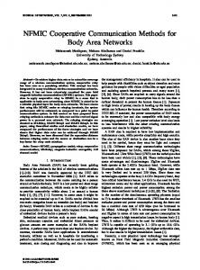
The PDR results for the UDP data transfer are plotted in Figure 11. Performance degradation has not been observed in the first handoff, but the second one implies two seconds of null connectivity. The connectivity gap is usually more evident in the second handoff, due to 802.11p technology is preferred when both 3G and 802.11p technologies are present. The handover mechanism waits for a Router Advertisement through 802.11p interface but, if this is is not received, the CoAHoA association timeout indicates that the 802.11p connectivity is over and the handoff to the 3G technology is performed. Moreover a great number of packet looses appear while the 802.11p link is used. This is explained by the fact that the 3G channels are allocated in the 900 Mhz band, whereas 802.11p channels are located in the 5.9 Ghz band, given to suffer more from obstructions to the signal propagation, such as other vehicles, building blocks or vegetation.
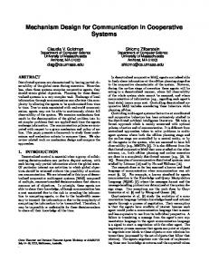
Figure 11. PDR results transmitting a UDP flow at 500 Kbps The network latency results are given in Figure 12. As can be seen, the 802.11p area is clearly visible with most of the RTT values under 10 ms, while 3G RTT results are more scattered (consider the logarithmic scale in the ordinate). Losses only appear during the second handoff. Here four messages are lost until the UMTS link is again used. Considering the results, network mobility and security modules perform efficiently under real intertechnology handoffs, the most difficult to accomplish. The communication stack operates correctly, maintaining the in-vehicle network connectivity in all tests and showing performance results that enable the communication stack to be used in many vehicular services. According to latency tests, even non-critical safety services could be implemented, such as emergency assistance, variable traffic signalling or kamikaze warning. Moreover, it is important to remark that this infrastructure-based vehicular communication approach is a real solution that could be deployed in the short term and it is also capable of allowing indirect
V2V communications, thanks to the global IPv6 scope of all in-vehicle hosts.
for non-critical vehicular services is necessary. In this line it is the work presented in [17]. Nevertheless, unlike the solution we propose, this contribution employs a constrained and non-autonomous communication stack that is used for experimental evaluation of concrete routing and flow management subsystems.
10. Conclusions
Figure 12. RTT results transmitting an ICMPv6 flow at 1 Hz rate
9. Related work Practical proposals for vehicular communications similar to the one presented in this paper are not frequent in the literature, due to the tough design and development efforts needed. For example, the work presented in [13] proposes an on-board solution for providing vehicular communications through an entity called “Car Gateway” acting as a mobile router. However, this solution is highly coupled with the vehicular platform and does not develop a generic communication stack to be instantiated on the different elements of an ITS network as encouraged by the ISO/ETSI guidelines for the development of cooperative vehicular systems. More related solutions can be found on recent proposals from FOT projects, since they offer the needed framework for implementing integral communication modules. In this sense, authors in [16] present the Drive C2X ITS station proposal, which is similar to the one presented in this paper, also offering an OSGi-based software platform for applications and dealing with communication issues at network level. However, what is noticeable in this work is that IP networking has been left out for UMTS-based communications for management and testing. A similar contribution can be found in [1] where authors present some investigations developed in the context of the simTD project. More precisely, this work introduces a novel communication architecture providing enhanced security and privacy communications thanks to the use of a public key infrastructure. Nevertheless, this solution does not integrate IP communications. IPv6 communications are the key to ITS cooperative systems deployment and, consequently, a combined solution for IPv6-based network mobility and security
This work proposes a networking stack that follows current ESO/ETSI trends encouraging the development of a common ITS communication architecture. The stack has been designed, the main modules implemented and a reference test-bed has been deployed using the network infrastructure available in the University of Murcia. The communication stack supports several communication technologies that can be automatically selected to provide connectivity to the vehicle. A secure IPv6 network mobility solution is proposed that combines NEMO and IPsec/IKEv2 to secure control and data traffic. Moreover, as part of the stack facilities and management features, the OSGi framework hosts both middleware and application software modules. IMS is used as a facility for making easier the service access to on-board applications, which are showed integrated in an extensible and friendly HMI. Finally, the communication stack supports novel geo-referenced facilities that allow applications to easily track vehicles and disseminate messages in specific segments of the road. Current future research directions lines at IPv6 level comprise an exhaustive testing of the secure IPv6 networking part. This is an on-going work that will analyse the impact of IKEv2 negotiation and IPsec tunnelling in vehicular communications. Moreover, extra security features to solve the privacy issues briefly presented in [18] are being analysed and a novel authentication scheme specially oriented to 802.11p (ETSI G5)-based networks is being defined. Regarding the network management, we are integrating the IEEE 802.21 technology and extending the current primitives defined in ETSI standards [19]. On the facility plane, we are currently extending our stack with a new DEMN (Decentralized Environmental Notification Message) module, which will be used for disseminating messages to vehicles from roadside units.
11. Acknowledgments This work has been sponsored by the European Seventh Framework Program, through the ITSSv6 (contract 270519) and FOTsis (contract 270447) projects; the Ministry of Science and Innovation, through the Walkie-Talkie project (TIN2011-27543-C03); and the Seneca Foundation, by means of the GERM program (04552/GERM/06). We would like to also thank ASN Lab for providing their ASN parsing software.
International Journal of ITS Research, Vol. X, No. X, May 2013
12. References [1] C. Weib, “V2X communication in Europe – From research projects towards standardization and field testing of vehicle communication technology”, Computer Networks, Elsevier, The Netherlands, 2011, pp. 3103-3119.
testbed for advanced vehicular services and communications”, In Proceedings 4th International Conference on Testbeds and Research Infrastructures for the Development of Networks & Communities, IEEE, USA, 2008.
[2] A. Festag. L. Le, M. Goleva, “Field Operational Tests for Cooperative Systems: A Tussle Between Research, Standardization and Deployment”, In Proceedings Eighth ACM international workshop on Vehicular inter-networking, 2011, Las Vegas.
[14] A. Amditis, L. Andreone, K. Pagle, G. Markkula, E. Deregibus, M. Romera, F. Bellotti, A. Engelsberg, R. Brouwer, B. Peters, A. De Gloria, “Towards the Automotive HMI of the Future: Overview of the AIDEIntegrated Project Results”, IEEE Transactions on Intelligent Transportation Systems, IEEE, USA, 2010, pp. 567-578.
[3] T. Kosch, I. Kulp, m. Bechler, M. Strassberger, B. Weyl, R. Lasowski, “Communication Architecture for Cooperative Systems in Europe”, IEEE Communications Magazine, IEEE, USA, 2009, pp. 116-125.
[15] ETSI TS 102 637-2: “Intelligent Transport Systems (ITS); Vehicular Communications; Basic Set of Applications; Part 2: Specification of Cooperative Awareness Basic Service”, March 2011.
[4] ISO 21217:2010, “Intelligent transport systems – Communications Access for Land Mobiles (CALM) – Architecture”, April 2010.
[16] R. Stahlmann, A. Festag, A. Tomatis, I. Radusch, F. Fischer, “Starting European Field Tests for Car-2-X Communication: The Drive C2X Framework”, In Proceedings 18th ITS World Congress and Exhibition 2011, ITS World Congress, USA, 2011.
[5] ETSI EN 302 665, “Intelligent Transport Systems (ITS); Communications Architecture”, September 2010. [6] J. Hubaux, S. Capkun, J. Luo, “The Security and Privacy of Smart Vehicles”, IEEE Security and Privacy, IEEE, USA, 2004, pp. 49-55. [7] M. Raya, P. Papadimitratos, J. Hubaux, “Securing Vehicular Communications”, IEEE Wireless Communications, IEEE, USA, 2006, pp. 8-15. [8] S. Céspedes, X. Shen, C. Lazo, “IP Mobility Management for Vehicular Communication Networks: Challenges and Solutions”, IEEE Communications Magazine, IEEE, USA, 2011, pp. 187-194. [9] V. Devarapalli, F. Dupont, “Mobile IPv6 Operation with IKEv2 and the Revised IPsec Architecture” , IETF RFC 4877, 2007. [10] P.F. Fernandez, F. Bernal, C. Nieto, A. F. GomezSkarmeta, “Mobility and security in a real VANET deployed in a heterogeneous networks”, Security and Communication Networks, John Wiley & Sons, USA, 2012, DOI: 10.1002/sec.518. [11] P. Eronen, “IKEv2 Mobility and Multihoming Protocol (MOBIKE)”, IETF RFC 4555, June 2006 [12] L. Foschini, T. Taleb, A. Corradi, D. Bottazzi, “M2M-Based Metropolitan Platform for IMS-Based Road Traffic Management in IoT”, IEEE Communications Magazine, IEEE, USA, 2011, pp. 5057. [13] C. Pinart, I. Lequerica, I. Barona, P. Sanz, D. García, D. Sánchez-Aparisi, “DRIVE: a reconfigurable
[17] M. Tsukada, J. Santa, O. Mehani, Y. Khaled, T. Ernst, “Design and Experimental Evaluation of a Vehicular Network Based on NEMO and MANET”, EURASIP Journal on Advances in Signal Processing, Springer, Germany, 2010, pp. 1-18. [18] J. Lee, T. Ernst, “Security Issues of IPv6 Communications in Cooperative Intelligent Transportation Systems”, In Proceedings 2011 IEEE Vehicular Networking Conference, IEEE, The Netherlands, 2011. [19] ISO 24102 : “Intelligent Transport Systems (ITS) – Communications access for land mobiles (CALM) Management”, September 2010.
José Santa received an MSc in Computer Engineering and an MSc in Advanced Information and Telematics Technologies in 2004 and 2008, respectively, and his PhD in Computer Science in 2009, all of them from University of Murcia, Spain. Currently, he is an Adjunct Professor in the Department of Information and Communication Engineering at the same university. His research interests include context awareness, intelligent transportation systems and indoor automation.
Fernando Pereñíguez is a postdoctoral researcher within the Department of Information and Communications Engineering at the University of Murcia. He received B.E., M.E. and Ph.D. degrees in Computer Sciences from University of Murcia in 2007, 2008 and 2011, respectively. He has participated in several projects funded by the Spanish government and the European Union. His research interests include security, privacy and handoff management in mobile networks.
Antonio Moragón received in 2005 the B.S. degree in Computer Engineering at the University of Murcia, Spain; in 2008 the M.S. degree in Advanced Information and Telematics Technologies. Nowadays he is an engineer in the Information and Communication Engineering Department. Most of his work has been focused on ITS, developing modular software prototypes to provide on-board services in various research projects.
Pedro J. Fernández received an MSc in Computer Science Engineering and an MSc in Advanced Information and Telematics Technologies in 2005 and 2007; both of them from University of Murcia, Spain. Currently, he is a PhD student and researcher in the Department of Information and Communication Engineering at the same university. His research interests include communication security protocols, intelligent transportation systems (ITS) and mobility.
Fernando Bernal Fernando Bernal received an MSc in Computer Science Engineering and an MSc in Advanced Information and Telematics Technologies in 2008 and 2009, respectively; all of them from University of Murcia, Spain. Currently, he is working as researcher and developer in the Department Information and Communications Engineering at the same university. His main research interests include authentication and authorization aspects in mobile networks.
Antonio F. Skarmeta received the M.S. degree in Computer Science from the University of Granada, Spain, and the B.S. (Hons.) and the Ph.D. degrees in Computer Science from the University of Murcia. In the period 1993-2010 he was an Assistant Professor and, since 2010, he is Full Professor with Department of Information and Communications Engineering at the same university. Research interests include mobile communications, artificial intelligence and home automation.