2010 IEEE Information Theory Workshop - ITW 2010 Dublin
Irregular Repeat-Accumulate-Like Codes with Improved Error Floor Performance David F. Hayes, Sarah J. Johnson, and Steven R. Weller School of Electrical Engineering and Computer Science The University of Newcastle, Callaghan, NSW 2308, Australia Email:
[email protected], {sarah.johnson, steven.weller}@newcastle.edu.au
Abstract—In this paper, we present a new class of iteratively decoded error correction codes. These codes, which are a modification of irregular repeat-accumulate (IRA) codes, are termed generalized IRA (GIRA) codes, and are designed for improved error floor performance. GIRA codes are systematic, easily encodable, and are decoded with the sum-product algorithm. In this paper we present a density evolution algorithm to compute the threshold of GIRA codes, and find GIRA degree distributions which produce codes with good thresholds. We then propose inner code designs and show using simulation results that they improve upon the error floor performance of IRA codes.
I. I NTRODUCTION Turbo-like error correction codes provide near-capacity error correction performance with practical encoding and decoding algorithms. This is achieved through the parallel, or serial, concatenation of two simple constituent convolutional codes via an interleaver and by decoding with an iterative algorithm which passes likelihood information between the two constituent decoders. Following this idea are low-density parity-check (LDPC) codes [1], which are iteratively decoded block codes re-discovered in the wake of turbo codes. Like turbo codes, LDPC codes use simple constituent codes, namely repetition codes and parity check codes. LDPC codes are decoded by iteratively passing likelihood values between component decoders using a graphical representation of the codes called their Tanner graph [2]. LDPC codes can offer lower complexity decoding than turbo codes and, for long irregular LDPC codes, performance within a fraction of a decibel (dB) of the Shannon limit on the additive white Gaussian noise (AWGN) channel [3]. Indeed, on the binary erasure channel it has been established that irregular LDPC codes can be decoded reliably at rates arbitrarily close to the channel capacity [4]. However, a disadvantage of LDPC codes is an encoding complexity which can be quadratic in the code length. A more recent addition to the family of capacityapproaching codes, repeat-accumulate (RA) codes [5], promises a solution to this problem. RA codes are formed by the serial concatenation of a repetition code, an interleaver, Π, which permutes the output of the repetition code, (optionally) a combiner, which sums (mod-2) a bits at a time the output of 1 the interleaver, and a rate-1 1+D convolutional code, called an accumulator. RA codes can be encoded using serial concatenation of the constituent encoders, as for serially concatenated turbo codes. An RA code can also be viewed as an LDPC code and decoded using sum-product decoding, thus gaining both the low encoding complexity of turbo codes and the decoding
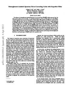
Fig. 1.
GIRA encoder
performance of LDPC codes. See e.g. [6] for a description of sum-product decoding, also known as belief propagation (BP) decoding. A regular RA code uses the same repetition rate and combiner rate for all message bits while an irregular RA (IRA) code repeats some message bits more than others as well as grouping some bits more then others at the combiner. Although simple and very easy to encode, IRA codes are powerful codes in their own right. Indeed, like irregular LDPC codes, IRA codes are capacity-achieving on the binary erasure channel [7]. Density evolution algorithms have been developed for IRA codes and IRA thresholds have been found within a fraction of a dB of capacity on AWGN channels [8]. Further, like LDPC codes, IRA codes show an interleaving gain in the word error rate (WER) as well as the bit error rate (BER). The IRA codes considered in [8] have been optimized for threshold and exhibit a poor error floor at high signal-to-noise ratios. One method of dramatically reducing the error floor with a small reduction in threshold is to fix the minimum repetition parameter to 3. In this paper, we present a class of IRA-like codes which generalize the accumulator of IRA codes to improve the error floor even further. These generalized IRA (GIRA) codes repeat message bits, interleave and combine just as in an IRA code, 1 as shown in Figure 1, but the inner code is no longer a 1+D convolutional code. Rather the inner code is chosen so that 3η a fraction 2+η of the bits it outputs are a function of two of its past input bits and the remaining fraction 2−2η 2+η of its output bits are a function of three of its past inputs bits. GIRA codes are systematic in that both the original message bits and the parity bits form the GIRA codeword. Using sum-product decoding, the decoding complexity of GIRA codes is only slightly increased over IRA codes. The Tanner graph of a GIRA code is shown in Figure 2. The bit nodes (shown as circles) correspond to the coded bits, while the check nodes (shown as squares) correspond to the parity-check equations that the codewords must satisfy. The systematic bit nodes correspond to the information bits while the parity bit nodes correspond to the parity bits output from
978-1-4244-8264-1/10/$26.00 © 2010 IEEE
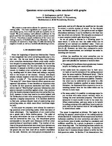
Fig. 2.
Tanner graph of a GIRA code.
the inner code. The graph has an edge between bit node α and check node β if the bit corresponding to α participates in the parity-check equation corresponding to β. We begin by presenting density evolution for these GIRA codes and derive their stability condition in Section II. We then propose inner codes for GIRA codes and consider code design in Section III, and conclude in Section IV. II. D ENSITY EVOLUTION For IRA and GIRA codes we distinguish between systematic edges, connecting systematic-bit nodes to check nodes, and parity edges connecting parity-bit nodes to check nodes. The edge degree distribution of the systematic edges is denoted (λ(x), ρ(x)), where λi is the fraction of systematic edges emanating from a degree-i systematic-bit node and ρi is the fraction of systematic edges emanating from a degree-i check node (where here the degree of the check node is the number of systematic edges to which it is connected). The edge degree distribution of the parity edges in a GIRA code are defined by the function λp (x) = ρp (x) = ηx + (1 − η)x2 , η ∈ [0, 1]. For code construction, the node degree distribution of the systematic edges, denoted by the functions v(x) = v2 x + · · · + vi xi−1 + · · · + vvmax xvmax −1 and h(x) = h1 x + · · · + hi xi−1 + · · · + hhmax xhmax −1 is useful. Here vi is the fraction systematic bit nodes with degree-i and hi is the fraction of check nodes with degree-i (where the degree of the check node is the number of edges connecting it to systematic-bit nodes). Translating between systematic edge degrees and node degrees: λi /i , vi = P j λj /j ρi /i , hi = P j ρj /j
(1) (2)
and for the parity edges: 3η , 2+η 2 − 2η . v3 = h 3 = 2+η
v2 = h 2 =
(3) (4)
A method for determining the expected performance on an AWGN channel of the ensemble of all codes with particular degree distribution, called density evolution (DE), was proposed for LDPC codes in [9], [10] and modified for IRA codes in [8]. For the AWGN channel, density evolution returns the largest noise variance (smallest signal-to-noise ratio) at which codes from an infinite length LDPC ensemble with a given degree distribution are expected to correct all of the errors [10]. The utility of density evolution stems from the Concentration Theorem [9] which guarantees that, with high probability, the BER after l iterations of the sum-product decoder applied to a randomly selected code in the ensemble and to a randomly generated channel noise sequence is close to the BER computed by density evolution, for sufficiently large block length. This signal-to-noise ratio is called the threshold of the degree distribution. The optimal degree distribution for a particular rate is found by optimizing the threshold over all admissible degree distributions using an optimization technique such as linear programming or differential evolution [9], [10]. The scheduling of the density evolution we use for GIRA codes is similar to that for IRA codes in [8] and based on the Tanner graph representation in Figure 2. Extrinsic information is passed from the systematic-bit nodes to the check nodes, from the check nodes to the parity-bit nodes, from the paritybit nodes back to the check nodes, and finally from the check nodes to the systematic-bit nodes, completing one decoder iteration. It can be shown that, for a binary-input symmetric-output channel, the distributions of the messages at every iteration of DE satisfy the symmetry condition such that, if F has density f [9]: f (x) = ex f (−x).
(5)
Distributions satisfying (5) are said to be symmetric. The bit error rate operator is defined by Pe(F ) =
1 − (F (0) + F (0)), 2
(6)
where F − (z) is the left-continuous version of F (z). We introduce the “delta at zero” distribution, denoted by ∆0 for which Pe(∆0 ) = 1/2, and the “delta at infinity” distribution, denoted by ∆∞ , for which Pe(∆∞ ) = 0. The symmetry property (5) implies that a sequence of symmetric distributions {F l }∞ l=0 converges to ∆∞ if and only if liml→∞ Pe(F (l) ) = 0. DE for GIRA codes is given by the following proposition whose derivation is omitted as its analogous to the derivation of DE in [8] for IRA codes. Proposition 1: Let Pl (respectively, P˜l ) represent the average distribution of messages passed from a systematic-bit node (respectively, parity-bit node) to a check node at iteration l. Also let Ql (respectively, Q˜l ) represent the average distribution of the messages passed from a check node to a systematic-bit node (respectively, parity-bit node), at iteration l.
Under the cycle-free condition, Pl , P˜l , Ql , Q˜l satisfy the following recursion: Pl = Fu ⊗ λ(Ql ), ˜ Q˜l ), P˜l = Fu ⊗ λ( ³ ´ Ql = Γ−1 ρ˜(Γ(P˜l−1 )) ⊗ Γ(P˜l−1 ) ⊗ ρ(Γ(Pl−1 )) , ³ ´ ˜ l = Γ−1 ρ˜(Γ(P˜l−1 )) ⊗ ρ (Γ(Pl−1 )) ⊗ Γ(Pl−1 ) , Q
(7) (8) (9) (10)
for l = 1, 2, . . . , with the initial condition P0 = P˜0 = ∆0 . Here Fu denotes the the distribution of the channel observation, ⊗ denotes convolution and X λ(F ) , λj F ⊗(j−1) , j
˜ ) , ρ˜(F ) = ηF + (1 − η)F ⊗2 , λ(F X ρ(F ) , ρj F ⊗(j−1) , j
where ⊗m denotes m-fold convolution, i.e. F ⊗(j−1) is the convolution of j − 1 copies of a distribution F . In the sum-product decoding algorithm the P outgoing message at a check node is the function γ −1 ( γ(m)), where γ(x) = (sign(x), − log tanh |x| 2 ), sign(x) is defined as in [8], and Γ(Fx ) is the distribution of γ(x). Lemma 1: Density-evolution is stable for GIRA codes whenever ¡ ¢ er er − 2η + η 2 λ2 ≤ r ′ . (11) e ρ (1) − ρ′ (1)(2η − η 2 ) + ρ¯(3η − η 2 ) Note that when λ2 = 0, the stability condition reduces to 2η − η 2 ≤ er which, for BI-AWGN channels, is always satisfied, so all GIRA codes with λ2 = 0 are stable. The proof of Lemma 1 is omitted due to space constraints. To find the threshold of GIRA ensembles on a binary-input AWGN channel we apply the recursions in (7), (8), (9) and (10) where the distribution Fu is determined by the signal-tonoise ratio (or noise variance) of the channel. The ensemble threshold is then the largest noise variance at which the bit error rate operator approaches zero as the number of iterations is allowed to increase without bound. A. Finding GIRA degree distributions To find a GIRA degree distribution, the rate, r, and fraction of degree-2 parity edges, η, are fixed and the set of allowed degree distributions is specified. The degree distributions which return the best threshold are found using differential evolution subject to the following constraints: P X X 1/ i ρii P P . λi = 1, ρi = 1, r = 1/ i ρi /i + 1/ i λi /i i i Thus three of the allowed λ, ρ parameters are dependant variables. Also the stability constraint (11) must be satisfied and any new degree distributions which do not meet (11) are discarded.
Example 1: The best rate 1/2 IRA ensemble from [8] is given by λ(x) = 0.04227x+0.16242x2 +0.06529x6 +0.06489x7 + 0.06207x8 +0.01273x9 +0.13072x10 +0.04027x13 + 0.00013x24 +0.05410x25 +0.13031x35 + 0.13071x36 +0.10402x99 , (12) and fixed combiner rate 8 (ie ρ7 = 1), has a threshold 0.059dB from capacity for the AWGN channel. We consider GIRA codes with the same rate and allowed degrees as this IRA ensemble but vary η, while keeping the same number of edges in the code. Fixing η = 1 returns an optimised IRA code, while reducing η reduces the number of degree-2 parity bit nodes in the Tanner graph and lowers the ensemble’s threshold. Varying η allows a tradeoff between a codes’ threshold and error floor. For example, the GIRA code with η = 0.772095 degree distribution λ(x) = 0.244439x2 + 0.080594x6 + 0.038783x7 + 0.026531x8 + 0.011140x9 + 0.154463x10 + 0.000330x13 + 0.076972x24 + 0.091514x25 + 0.120244x35 + 0.064810x36 + 0.090181x99 , ρ(x) = 0.146894x6 + 0.853106x7
(13)
has a threshold 0.244dB from capacity for the AWGN channel. We can also remove degree-2 systematic nodes to lower the error floor. The λ2 = 0 IRA code is given by λ(x) = 0.240455x2 + 0.045267x6 + 0.080683x7 + 0.0116825x8 + 0.055066x9 + 0.087685x10 + 0.050631x13 + 0.020880x24 + 0.081912x25 + 0.149727x35 + 0.054048x36 + 0.121972x99 ,
(14)
and constant combiner rate 8, has a threshold 0.14 dB from capacity for the AWGN channel. III. D ESIGN OF THE I NNER CODE 1 convolutional code In an IRA code the inner code is a 1+D which simply outputs the sum of the past input bit and previous output bit for each output. This has the advantage of being very easy to implement at the encoder. However, when λ2 > 0, the large number of degree-2 nodes introduce an error floor as the inclusion of degree-2 nodes leads to the ensemble as n → ∞ having a non-zero probability of weight-2, codewords bounding the word error probability away from zero [11]. Figure 3(b) shows the w3IRA inner code and (c) shows the (η, s)-GIRA inner code. The inner code of a GIRA code on the other hand must vary 3η are the number of past outputs that each output sums ( 2+η 2−2η summed once and 2+η are summed twice). We consider two ways to design and implement an inner code to implement a GIRA code in practice. The first, called w3IRA codes in [12], use a 1 (15) 1 + D + Dψ+1
Fig. 3.
The inner codes for (a) IRA, (b) w3IRA, (c) (η, s)-GIRA codes
convolutional code as the inner code and the second, which we propose here, and call (η, s)-GIRA, functionally uses the same inner convolutional code but switches the Dψ+1 on every (s + 1)th output and off otherwise, to spread out the weight-3 parity bit-nodes in the Tanner graph. A. w3IRA codes The integer ψ from the w3IRA inner code (15), becomes a design parameter used to control the number of weight-2 parity bit nodes in the code Tanner graph. To achieve our GIRA codes we will employ a w3IRA inner code by setting 3η M − 1. ψ = 2+η Using this inner code allows us to implement GIRA codes without losing the low complexity encoding advantage of IRA codes. The parity bits output by the w3IRA inner code are described by i = 1, ri , pi−1 ⊕ ri , i = 2, . . . , ψ + 1, pi = (16) pi−1 ⊕ pi−ψ−1 ⊕ ri , i = ψ + 2, . . . , M. where ri is the ith output bit from the combiner.
B. (η, s)-GIRA The disadvantage of the w3IRA inner code is that it introduces 6-cycles between the weight-2 and weight-3 parity bit nodes. We therefore propose an alternative inner code which increases the length of the smallest cycle inside the inner code while maintaining the encoding complexity. The weight3 parity bit nodes are separated by an integer parameter s in the parity-check matrix. The size of the minimum cycle then becomes 6 + 4s, and ψ for (η, s)-GIRA codes is redefined as ψ = f (η, s, M ) = (s + 1)M
3η − Ms − 1 2+η
(17)
The parity bits are given by: ri , pi−1 ⊕ ri , pi−1 ⊕ ri , pi = pi−1 ⊕ pi−ψ−1 ⊕ ri ,
i = 1, i = 2, . . . , ψ + 1, i = ψ + 2, . . . , M, (i − 2 − ψ) mod s 6= 0, i = ψ + 2, . . . , M (i − 2 − ψ) mod s = 0. (18) output bit from the combiner.
Where ri is the ith Example 2: The inner code section of the parity-check matrix due to a M = 9 (0.7, 1)-GIRA accumulator is shown below, in which
it can be seen that ψ = 4 and the size is 10: 1 0 0 0 0 0 1 1 0 0 0 0 0 1 1 0 0 0 0 0 1 1 0 0 H2 = 0 0 0 1 1 0 1 0 0 0 1 1 0 0 0 0 0 1 0 0 1 0 0 0 0 0 0 0 0 0
of the minimum cycle 0 0 0 0 0 0 0 0 0 0 0 0 0 0 0 . 0 0 0 1 0 0 1 1 0 0 1 1
It can be seen that M > 2−2η 2+η M s − 1, giving the maximum 2+η size of s, s ≤ ⌊(1 + 1/M ) 2−2η ⌋. There is one further type of cycle within the (η, s)-GIRA accumulator, connecting one weight-3 parity bit node with the diagonal and subdiagonal. Its cycle length is given by 4 + 2(M − (s + 1)ψ).
(19)
Figure 3(c) shows the (η, s)-GIRA inner code, that switches the Dψ+1 component on for every (s + 1)-th bit from the combiner. By varying the parameter s, we can vary the length and number of cycles in the inner code, reducing the error floor. With this definition of (η, s)-GIRA we can re-interpret IRA codes as the subclass of (1,0)-GIRA codes and w3IRA codes as the subclass of (η,0)-GIRA codes. Example 3: The message m = [ 0 1 0 1 ] is to be encoded using a length-11 (0.625,1)-GIRA code consisting of a repetition code repeating the first two message bits three times and the next two message bits four times (λ = 0.33x + 0.67x3 ), a constant combiner rate 2 (ρ = x), interleaver Π = [1, 4, 5, 11, 2, 7, 8, 12, 6, 13, 9, 14, 3, 10]. Substituting M = 7 and η = 0.625 into (17) gives ψ = 2 First the message bits are passed through the repetition encoder to give b = [ 0 0 0 1 1 1 0 0 0 0 1 1 1 1 ]. Second b is interleaved producing d = [ 0 1 1 1 0 0 0 1 1 1 0 1 0 0 ]. Next, the combiner sums each set of 2 bits to give r = [ 1 0 0 1 0 1 0 ] and finally, the inner code produces the parity bits p = [ 1 1 1 1 1 1 1 ]. For the first parity bit p1 = d1 ⊕ d2 = m1 ⊕ m2 so the first parity-check equation is c1 ⊕ c2 ⊕ c5 = 0 where c1 . . . cK = m1 . . . mK and cK+1 . . . cN = p1 . . . pM . Similarly, the fourth parity bit is given by p4 = p3 ⊕p1 ⊕d7 ⊕d8 = p3 ⊕p1 ⊕m3 ⊕m4 so the fourth parity-check equation is c3 ⊕ c4 ⊕ c5 ⊕ c7 ⊕ c8 = 0. Repeating for all of the parity check equations gives the (0.625, 1)-GIRA parity-check matrix: 1 1 0 0 1 0 0 0 0 0 0 0 1 0 1 1 1 0 0 0 0 0 1 0 1 0 0 1 1 0 0 0 0 H = 0 0 1 1 1 0 1 1 0 0 0 . (20) 0 1 0 1 0 0 0 1 1 0 0 0 0 1 1 0 0 1 0 1 1 0 1 0 1 0 0 0 0 0 0 1 1
is affected by the large number of weight-2 Tanner graph nodes required by the accumulator. By defining GIRA codes we now have easily encodable codes with significantly more flexibility in choosing their degree distributions. Thus (η, s)-GIRA codes provide all the benefits of IRA codes as well as very good error floor performance for only a small sacrifice in threshold. It is important to note that this paper focuses only on modifying the inner code of an IRA code as a means of reducing the error floor. Other methods such as interleaver design, modifying the sum-product algorithm and adding an outer code [14] are also applicable to GIRA codes and may further improve their error floor performance.
−1
10
IRA IRA λ = 0 2
−2
10
w3IRA (0.772,1)−GIRA (0.772,2)−GIRA
−3
10
−4
Bit error rate
10
−5
10
−6
10
−7
10
−8
10
−9
10
−10
10
0.5
1 1.5 Signal−to−noise ratio Eb/N0 (dB)
2
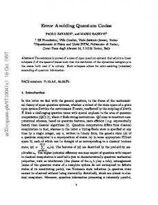
Fig. 4. Error correction performance on an AWGN channel of rate-1/2, length-10,000 codes with degree distribution (12)–(14), decoded with sumproduct decoding with a maximum of 1000 iterations.
C. Results Fig. 4 shows the BER performance on the AWGN channel of IRA, w3IRA and (η, s)-GIRA codes with the degree distributions (12), (13) and (14), decoded using sum-product decoding. To compare the type of codes, independently of the interleaver/parity-check matrix design, codes with completely random interleaver constructions have been simulated. It can be seen that optimizing the threshold of IRA codes subject to λ2 = 0 improves the error floor over the IRA codes from (12). However, further substantial improvement in the error floor can be made with (η, s)-GIRA codes for a minimal effect on the threshold. For the case of s = 1, at an SNR of 2dB, 8 × 10⁷ blocks were simulated with only 20 errors detected, showing that reducing the number of weight-2 parity bit nodes and increasing the cycle length among the parity edges has a marked improvement on the error floor. GIRA codes can be encoded using serial concatenation of the constituent codes, and decoded using sum-product decoding on the Tanner graph of the code, as for IRA codes but offer a much more flexible degree distribution than conventional IRA codes, allowing us to improve upon the error floor performance of both IRA and w3IRA codes. Note that if the GIRA codes were to be decoded with turbo decoding, choosing an encoder with large ψ would dramatically increase the complexity of the BCJR decoder for the inner convolutional component code. However, using sumproduct decoding on the code’s Tanner graph the decoding complexity of (η, s)-GIRA codes will be only slightly increased over that of IRA codes due to the extra edges between the parity-bit and parity-check nodes in the Tanner graph. The GIRA encoder will require a length ψ shift register, and one additional modulo-2 summation per parity bit, and also require logic to switch the Dψ+1 component of the inner code on and off. For LDPC codes it has always been possible to trade off threshold performance for improved error floors by increasing the bit node degrees, see e.g. the Euclidean and projective geometry codes [13]. However, the error floor of IRA codes
IV. C ONCLUSION In this paper we have proposed a new class of iterative error correction codes, termed GIRA codes, and considered two main issues in their design: replacing the accumulator, and choosing the degree distributions. We have shown that GIRA codes can be designed to improve upon the error floor performance of traditional IRA codes with only a small sacrifice in threshold, and have presented methods to construct GIRA codes with low implementation complexity. R EFERENCES [1] R. G. Gallager, “Low-density parity-check codes,” IRE Trans. Inform. Theory, vol. IT-8, no. 1, pp. 21–28, January 1962. [2] R. M. Tanner, “A recursive approach to low complexity codes,” IEEE Trans. Inform. Theory, vol. IT-27, no. 5, pp. 533–547, September 1981. [3] S.-Y. Chung, G. D. Forney, Jr., T. J. Richardson, and R. L. Urbanke, “On the design of low-density parity-check codes within 0.0045 dB of the Shannon limit,” IEEE Commun. Letters, vol. 5, no. 2, pp. 58–60, February 2001. [4] M. G. Luby, M. Mitzenmacher, M. A. Shokrollahi, D. A. Spielman, and V. Stemann, “Practical loss-resilient codes,” in Proc. 30th ACM Symp. on the Theory of Computing, 1998, pp. 249–258. [5] D. Divsalar, H. Jin, and R. J. McEliece, “Coding theorems for “turbolike” codes,” in Proc. 36th Allerton Conf. on Communications’, Control, and Computing, Allerton, Illinois, September 1998, pp. 201–210. [6] D. J. C. MacKay, “Good error-correcting codes based on very sparse matrices,” IEEE Trans. Inform. Theory, vol. 45, no. 2, pp. 399–431, March 1999. [7] H. Jin, D. Khandekar, and R. J. McEliece, “Irregular repeat-accumulate codes,” in Proc. of the Second International Symposium on Turbo Codes and Related Topics, Brest, France, September 2000, pp. 1–8. [8] A. Roumy, S. Guemghar, G. Caire, and S. Verd´u, “Design methods for irregular repeat-accumulate codes,” IEEE Trans. Inform. Theory, vol. 50, no. 8, pp. 1711–1727, August 2004. [9] T. J. Richardson and R. L. Urbanke, “The capacity of low-density paritycheck codes under message-passing decoding,” IEEE Trans. Inform. Theory, vol. 47, no. 2, pp. 599–618, February 2001. [10] T. J. Richardson, M. A. Shokrollahi, and R. L. Urbanke, “Design of capacity-approaching irregular low-density parity-check codes,” IEEE Trans. Inform. Theory, vol. 47, no. 2, pp. 619–637, February 2001. [11] H. Jin, D. Khandekar, and R. J. McEliece, “Irregular repeat-accumulate codes,” in Proc. of the Second International Symposium on Turbo Codes and Related Topics, Brest, France, September 2000, pp. 1–8. [12] S. J. Johnson and S. R. Weller, “Combinatorial interleavers for systematic regular repeat-accumulate codes,” IEEE Trans. Commun., vol. 56, no. 8, pp. 1201–1206, August 2008. [13] Y. Kou, S. Lin, and M. P. C. Fossorier, “Low-density parity-check codes based on finite geometries: A rediscovery and new results,” IEEE Trans. Inform. Theory, vol. 47, no. 7, pp. 2711–2736, November 2001. [14] Y. Han and W. Ryan, “Low-floor decoders for LDPC codes,” Communications, IEEE Transactions on, vol. 57, no. 6, pp. 1663 –1673, June 2009.