high performance dies, (d) exploiting vertical proximity of hardware ...... [21] J. Li and E. Swartzlander Jr, âConcurrent error detection in ALUs by recomputing ... [31] N. Sillon, A. Astier, H. Boutry, L. Di Cioccio, D. Henry, and P. Leduc,. âEnabling ...
Is 3D Integration the Way to Future Dependable Computing Platforms? Saleh Safiruddin, Demid Borodin, Mihai Lefter, George Voicu, Sorin Dan Cotofana Faculty of EE, Mathematics and CS Delft University of Technology Delft, The Netherlands {s.safiruddin, d.borodin, m.lefter, g.r.voicu, s.d.cotofana}@tudelft.nl
Abstract—Achieving dependable computing systems is becoming increasingly more difficult as CMOS integrated circuits technology scaling reaches sub-22nm ranges and faces physical limitations. Dependable computing is also a major concern with the various new technologies that are being investigated to overcome the physical limitations of CMOS technology. 3D integration, though initially proposed as a way of achieving speedup of integrated circuits without the need for scaling, offers many new opportunities for dependable computing. 3D integration adds two new dimensions to the design space: (i) the z-dimension, as now the application can be mapped on parts of the circuit that are placed in different planes, and (ii) the R-dimension as different planes can be selected with different reliabilities. This greatly expands the solution space and provides many opportunities to deal with new and existing challenges. In this paper we identify important strategies to achieve dependable computing by exploring the opportunities that 3D integration offers. We present systems level approaches for alleviating underlying technology reliability shortcomings and investigate the opportunities opened up by TSV-based 3D integration with emphasis on the system reliability point of view. Our investigation clearly indicates that the proposed 3D dependable computing paradigms, if developed and further explored, can facilitate the continuation of the trend of reducing package size and increasing transistor densities, and allow for the successful utilization of novel emerging unreliable devices. Index Terms—3D integration; dependable computing; fault tolerance; reliability; through-silicon vias.
I. I NTRODUCTION Achieving dependable computing systems is becoming increasingly more difficult as CMOS integrated circuits technology scaling reaches sub-22nm ranges, see chapter “Emerging Research Devices” in [1]. Fundamental limitations are seeming to be approached related to, among others, scaling and power dissipation. Interference from external physical phenomena start dominating, making it a major challenge to, firstly, correctly manufacture circuits, and secondly, to have correctly functioning devices in the presence of run-time interference. This is leading us into a new era where a focus on dependable computing is once again required to address unreliable circuit technologies. Dependable computing is also a major concern in relation with the various new alternative technologies that are emerging and being investigated to overcome the aforementioned fundamental limitations of CMOS technology. These include Molecular devices, Spintronics, Ferromagnetic logic, and Sin-
978-1-4673-1653-8/12/$31.00 '2012 IEEE
gle Electron Tunneling technology, see chapter “Emerging Research Devices” in [1]. Even though these technologies have much higher device densities when compared to CMOS, the device reliability is in most cases a major concern and the main hurdle in the way of their practical utilization. Thus, a focus on dependable computing is imperative for the successful adoption of these technologies. 3D integration technology, although initially proposed as a way of achieving integrated circuit speed-up without the need for scaling, offers many new opportunities for dependable computing. The push for 3D integration was mainly due to three reasons: interconnect latency reduction, heterogeneous integration, and significant reduction in form factor. From the various methods of achieving 3D integrations, the use of Through Silicon Vias (TSV) has the potential to become widely adopted, see chapter “Interconnect” in [1]. In TSVbased 3D Stacked Integrated Circuits (3D-SIC) dies are stacked vertically on top of each other and are interconnected using vias which travel through the silicon. Furthermore, dies of different technologies can be integrated in the same stack and a reduction of physical space required by the stacked chip is achieved due to vertical stacking. Thus, in 3D integrated circuits, a device can be placed in a 3-dimensional space instead of just a 2-dimensional one, and additionally, a device can be placed on dies with different reliability. The solution space is thus greatly expanded offering many opportunities to design dependable 3D integrated-, nanoscale device-, and future-technology-based systems. In this paper we identify important strategies to achieve dependable computing by exploring the opportunities that 3D integration offers. We present and analyze various system level approaches for alleviating underlying technology reliability shortcomings and achieving dependable computing systems. We also argue that the proposed 3D specific mechanisms for dependable computing, if developed and further explored, can facilitate the continuation of the trend of reducing package size and increasing transistor densities, and allow for the successful utilization of new technologies with unreliable devices. In particular, we investigate the opportunities opened up by TSV-based 3D integration with emphasis from the system reliability point of view. Essentially speaking, when mapping a certain application, the 3D integration is adding two new
1233
dimensions into the design space: (i) the z-dimension, as now the application can be mapped on parts of the circuit that are placed in different planes, and (ii) the R-dimension as different planes can be selected with different reliabilities. This makes the design space exploration more complex, as it is a lot larger than in the 2D case, but certainly creates more area-powerperformance-reliability tradeoff opportunities. The directions that we identify are based on: (a) utilization of dies of higher reliability for computation verification, (b) utilization of dies of higher reliability for critical systems parts, (c) placing more computationally intensive units on high performance dies, (d) exploiting vertical proximity of hardware, (e) checkpointing utilizing dies of different reliability, and (f) dedicating separate reliable dies for management, diagnosis and system repair. Our analysis clearly suggests that focussed research in these directions and the application of these strategies will open the path for the further development of 3D integration-, nanoscale-, and future-technology systems. The remainder of the paper is organized as follows: in Section II we give an overview of dependable computing, and fault tolerance in particular. In Section III we present 3D stacked integrated circuit technology. We map out the various possibilities to achieve 3D integration and present the introduced advantages and limitations. In Section IV we discuss the introduction of the two new dimensions in the design space and their implications regarding dependable computing. In Section V we present the avenues of research opened up by the extension of the design space, and the systemlevel strategies that can be employed to achieve dependable computing. We conclude the paper with a summary of our analysis in Section VI. II. D EPENDABLE C OMPUTING : BACKGROUND In this section we give a background of various terms, concepts, methods and approaches used throughout the content of this paper. According to Avizienis [2] dependable computing is ”the ability to deliver service that can justifiably be trusted”. It integrates attributes such as availability, reliability, safety, integrity and maintainability. One of the means to achieve dependability is by employing Fault Tolerance (FT). Avizienis [3] defines FT as ”the ability to execute specified algorithms correctly regardless of hardware failures and program errors”. The main fault categories we consider are natural hardware, transient and permanent faults (mostly operational). However, in some cases, other classes of faults, such as development and human-error, can also be addressed by the proposed mechanisms for dependable computing, but only partially. Both internal and external phenomena can cause natural hardware faults. Internal faults can be caused by physical deterioration resulting from internal processes, such as cross talk between wires, wire wearing-out etc. External faults can be caused by external processes originating outside the system and physically interfering with it, possibly penetrating into the system. Such external processess include radiation, external
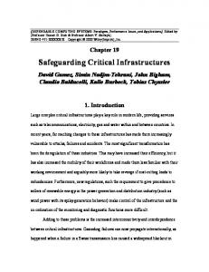
Fault Tolerance
Information Redundancy Additional data, may be HW.
Space Redundancy Additional HW.
Active Redundancy
Passive Redundancy
Error detection, enabling standby spares. For long-life high-availability systems.
N-modular redundancy, ECC, etc. For long-life high-availability systems.
Time Redundancy Performance penalty.
Hybrid Redundancy Combines active and passive redundancy. The most expensive and effective method
Figure 1: Protective Redundancy Types.
magnetic fields, thermal influence, etc. Internal and extrenal sources can both lead to transient as well as permanent hardware faults in the system. FT is based on some form of redundancy. It can be in the form of space, information, or time redundancy. Figure 1 summarizes the redundancy types. With space redundancy, extra hardware resources are utilized to achieve FT. This usually leads to significant cost increases, but performance degradation is avoided. For information redundancy, some extra information is required for FT purposes, such as parity bits. Additional resources and/or time is required to generate and use this information. In time redundancy, an operation is sequentially performed several times and the results are compared. This does not increase the system cost, but significantly degrades performance. Redundancy of any type can appear in the form of additional hardware and/or software, which verifies the functionality of the system. Generally, different forms of redundancy are combined to achieve an optimal result with the minimum specific type of overhead. Active redundancy is the least costly form of FT, and is based on error detection followed by appropriate actions. For example, the faulty hardware unit can be disabled and its standby spare enabled, if it exists (otherwise, graceful degradation happens). The system will perform as long as at least one working unit is available. This approach typically does not correct the detected error, thus it is only suitable for systems that can tolerate a temporary erroneous result and it is often used in long-life and high-availability systems. Error detection can be achieved by various techniques such as duplication with comparison, error detection codes, self-checking logic [4], watchdog timers, consistency and capability checks, and others [5], [6], [7]. Passive redundancy is more costly and employs fault masking techniques, such as N-Modular Redundancy, ECC, masking logic, etc. Passive redundancy does not allow faults to propagate to the outputs and is thus more suitable for critical applications. The most costly but at the same time the most effective is the hybrid form incorporating both passive and active redundancy. For example, the hybrid redundancy can use multiple identical hardware units verifying each other (providing fault masking), and spare unit(s). When a unit fails, it is replaced with a
1234
spare one, keeping the system protected. Figure 1 classifies the discussed types of redundancy. One of the basic FT masking techniques is by utilizing the concept of Triple Modular Redundancy (TMR). This was developed and analyzed by John von Neumann in 1950s [8]. The scheme involves three identical blocks receiving the same inputs, which are expected to produce the same outputs. All the outputs are directed to a voter, which assumes that two or three matching values present the correct output, and masks the third one if it deviates, considering it to be faulty. TMR is able to detect multiple errors, as long as two outputs do not agree on a wrong value, and correct one error. A reduced version of TMR is duplication with comparison, which is only able to detect errors, provided these errors do not affect the outputs of both blocks in the same way. TMR can be extended to N-Modular Redundancy, which uses N identical blocks, and performs a majority voting on the results. In TMR, N equals 3, and in duplication with comparison N equals 2. The N-Modular Redundancy technique can be applied at any level, from discrete transistors to whole systems, as well as for any redundancy method (space, information, and time redundancy in hardware or software). The only practical application of component-level redundancy (the discrete transistor level) is found in the PPDS computer used in NASA’s Orbiting Astronomical Observatory (OAO-2) satellite launched in 1968 [9]. It is one of the latest computers assembled from discrete transistors [10]. PPDS utilizes masking (quadruple) redundancy at component level: instead of one transistor of a non-redundant system, there are four of them, implemented in such a way that a failed transistor is masked by the others. This technology is not adequate for integrated circuits because the independence of adjacent components’ failures cannot be guaranteed. N-Modular Redundancy in software takes the form of N-version programming [11] The voter for N-Modular Redundancy is the weak spot, which must provide a reliability level appropriate for the multiplicated module whose functionality it verifies. The utility of N-Modular Redundancy depends on the weakness of the voter, since having incorrect voter outputs would generate incorrect conclusions about the functioning of the multiple modules. The reliability of voters has been studied in [12] and some effort has been made to improve it. This is achieved, for example, by creating self-testing voters [13], [14] and by using a transistor redundancy approach [15], in which faults in the voter are masked at the transistor level. A voter which compares whole output words rather than separate bits has been proposed to minimize the risk of an improper agreement report [16]. In addition to the vulnerability of the voter, all pure N-Modular Redundancy techniques are susceptible to common failures [17]. Common failures affect the outputs in the same way, so that all the modules produce the same erroneous output, which is accepted by the voter. The basic form of time redundancy is recomputing (performing the same computation multiple times) with results comparison. This scheme aims at detecting transient (temporary) faults only. The problem of recomputing on hardware
with a permanent fault is the same as that of simultaneous computing on multiple hardware units with common faults: the faults affect the results in the same way, the outputs match, so the error is not detected. However, there exist space redundancy schemes covering common faults, and time redundancy schemes covering permanent faults. These schemes change the form of the inputs (encode them) and expect to get matching results after performing an appropriate compensating transformation (decoding) of the output. These transformations guarantee that common and permanent faults affect results in different ways. Examples of such techniques are alternating logic [18], alternate-data retry [19], recomputing with shifted operands [20], recomputing with rotated operands [21], and recomputing with swapped operands [5]. There are also hybrid schemes combining hardware and time redundancy, such as recomputing using duplication with comparison [22] and its enhancements [23], [24]. In order to minimize the cost of the applied redundancy, Huang and Abraham [25] proposed algorithm-based FT, which utilizes the properties of particular algorithms. Algorithmbased FT designs provide a high level of FT at an extremely low cost when compared to the universal methods discussed above. However, algorithm-based FT methods need to be designed specifically for every algorithm. Huang and Abraham [25] considered matrix operations as an example. Input matrices are encoded by adding a column and/or row containing the sum of all the elements in the corresponding row/column. Matrix operations are performed on these encoded matrices. The results are decoded, providing error detection and location. For more information on traditional FT techniques we refer to [5], [6], [7]. In this paper we leverage specific properties of 3D integrated systems in order to increase the overall system dependability. In the next section we give and overview of 3D integration technology. III. 3D S TACKED I NTEGRATED C IRCUITS T ECHNOLOGY Conventional integrated circuits consist of two-dimensional planar arrays filled with transistors connected by metal wires. This approach, though having served well in the development of integrated circuits, does not efficiently make use of the vertical dimension. By harnessing the third vertical dimension, the technology to manufacture 3D Stacked Integrated Circuits (3D-SIC) is emerging as a promising avenue to sustain the trends of reducing package size and increasing transistor densities. Along with this, the problems related to long interconnects in planar circuits, including power dissipation and latency can also be mitigated. In the last few years, 3D-SIC technology has garnered a lot of interest and significant technological progress towards commercial availability has been made. The first ideas having been envisioned as early as 1960 [26], the technology is now relatively mature and 3D-SIC stacked technology is predicted to enable further progress according to Moore’s law beyond the current limitations, due to the alleviation of the interconnect length bottleneck, among others.
1235
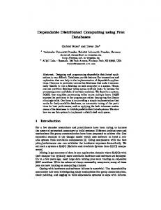
Available 3D packaging techniques like System-in-Package stack several 2D chips together in the same package and connects them with solder wires or bumps. However, the chips are still independent entities which communicate through off-chip signaling. In contrast, a 3D Integrated Circuit is a single circuit made of several layers containing active devices, i.e. transistors, with vertical connections possible between layers [27]. Two manufacturing approaches are currently prototyped. The monolithic approach uses a single silicon wafer to build all transistors in the circuit and the wiring between them [28]. The fabrication process makes use of a sequence of standard CMOS steps and does not require additional bonding related steps. However, it is difficult to achieve acceptable yield due to the fact that transistors formed on higher layers require high temperature processes which will potentially destroy already formed metal wires. The alternative consists in manufacturing each layer on a separate silicon wafer and then bond either the wafers, sliced dies, or sliced dies to unsliced wafers to create 3D chips (see Figure 2). Although the involved fabrication steps are more numerous, they are well known, and at the moment they can achieve promising yields. Numerous schemes are being investigated and researched to achieve the latter 3D stacked integration, including wire bonds, micro-bumps, solders balls, and Through Silicon Vias (TSVs) [29], [30], [36]. Utilizing TSVs as interconnects between stacked planar dies is considered to have high potential in meeting the emerging challenges for 3D integration, making it highly likely to become widely adopted [1]. Moreover, key players in the semiconductors industry have already announced stacked chip products with TSVs [32], [33]. TSV-based 3D-SIC technology adoption is driven by a number of motivations, described as follows: 1) Interconnect latency reduction The continuous down-scaling of transistor feature size has shifted the dominant latency factor from the device itself to the interconnection wires [34]. Contemporary TSVs are copper pillars with a 5-10 µm diameter, with electrical properties comparable with normal metal wires. The length of a TSV is currently limited by the silicon wafer height at about 20-40 µm. By placing adjacent blocks on top of each other, millimeter long wires can now be shortened to the micrometer lengths of the TSV. This gain is also exacerbated due to the fact that with current CMOS technology the RC delay of a wire is increasing exponentially with scaling making it an important issue. The parasitic capacitance of the TSV, typically 30-40 f F , has the predominant effect on the delay. Its resistance has an unnoticeable effect, while the inductance has a noticeable effect only at signal frequencies above 3GHz [35]. 2) Power consumption reduction Shortening of wires also has a direct effect on the power usage as less heat is dissipated in the wires. Although a TSV dissipates more heat than a normal horizontal metal wire, the significant reduction in total wirelength
compensates so that the global power consumption is lower for a 3D stack. Even more larger power savings are obtained through the removal of now obsolete powerhungry transceivers for inter-die communications links, i.e., high speed parallel and/or serial links between processing cores or between cores and memory. 3) Heterogeneous integration The ability to integrate heterogeneous technologies onto the same chip has been one of the first and main drivers as there are a large number of applications which can benefit greatly from this, ranging from micro- and nanosensors with Micro-/Nano- Electro-Mechanical-Systems and CMOS logic layers to high-performance computing cluster nodes with optical, memory and logic layers. Furthermore, various emerging technologies proposed to replace CMOS-based computing can use 3D-SIC technology as an enabler for hybrid transitional circuits. 4) Form factor Apart from the system architecture motivations, the form factor of the complete system plays an important role. Many applications would benefit from miniaturization and new applications could be introduced [36]. The migration from the 2D to 3D technology is expected to introduce both problems and new opportunities for the design of dependable systems out of unreliable components. TSV’s allow for a vast variety of 3D integration possibilities and currently many different techniques are under investigation for the via connections [37]. To achieve a viable 3D-SIC TSV-based system, there are many issues that have to be dealt with, including power distribution, clock distribution, and TSV-based inter-die communication. Inter-die communication is one of the key issues, as any failure may potentially result in the entire system becoming unusable. In order to increase the yield and system life-time of 3D-SICs, both manufacturing TSV defects and defects occurring during system operation must be addressed. Additional effort is thus required to ensure reliable data transfer between the layers. Thus, one of the key factors determining the overall reliability of a 3D mapped application is the TSVs reliability. If this is not sufficient, protective methods have to be applied to the TSVs to maintain the same reliability level. For this end, well-known techniques, e.g., redundant TSVs or error detection and correction codes can be used. On the other hand, as discussed in the next sections, the introduction of two new dimensions in the design space enables the utilizations of novel reliability oriented approaches, which are not applicable for planar 2D chips. IV. 3D-SIC’ S 4-D IMENSIONAL D ESIGN S PACE Two unique features of 3D integration present us with new opportunities for dependable computing by extending the design space for integrated circuits. The first feature arises from the fact that 3D integration involves the vertical stacking of dies and thus we have the added freedom to place hardware on extra spatial planes. This extends the design space with the vertical, or z-dimension. The z-dimension is in fact a discrete
1236
Figure 2: An example of a heterogenous 3D-SIC (left) with a detailed cross-section across the layers (right). Note: dimensions not to scale.
layered dimension, physically represented by the stacked dies. Since dies can now be interconnected from virtually any area on one die to any chosen point on another die, and with a very low interconnect latency, a new freedom degree has been introduced and can be exploited during the design space exploration process. The introduction of the third dimension in 3D circuits has important consequences on system performance but also on reliability. The possibility to shorten on-chip wires contributes the most to the performance, while the third dimension consequences on reliability are listed below: •
Reduced fault probability with shorter wires As mentioned above, the 3D integration technology is capable of reducing the wire length. This by itself contributes to the wires reliability, because longer wires have a greater chance to encounter faults. This, however, is true under the condition that the TSVs themselves are sufficiently reliable. In the case they are not, redundancy can be utilized to verify the signal correctness. Space redundancy, however, assumes that the number of TSVs increases to accommodate the redundant signals. As mentioned above, increasing the number of TSVs is, for the time being, not a realistic option because this results in a large area overhead. Thus, time redundant methods can be considered to compensate for the lack of TSVs reliability. Given that the signal propagation time is reduced by a factor of several times by using the TSVs instead of long on-chip wires, the signal can be sent a couple of times instead of once, while still achieving a
1237
•
certain performance benefit. Fewer common faults on replicas placed on different dies One of the implications of feature size reduction is the increased probability of common hardware faults. Common faults appear when two redundant units produce the same faulty output due to a fault affecting both of them in a similar way. This can happen, for example, when a particle strikes two wires at the same time, leading to a bit flip in both of them. If these wires belong to two redundant units verifying each other, and the affected wires correspond to each other in the redundant units, the error propagates similarly in both units. As a result, the units produce the same faulty output. The erroneous results match and thus their comparison does not reveal the error. This leads to an undetected common fault. On a single die, redundant units are likely to appear close to each other, to avoid long connections between them. Large redundant units such as complete CPUs are unlikely to suffer from common faults, because their corresponding wires are unlikely to be placed close to each other. However, smaller redundant units can be expected to suffer from common faults. Placing these redundant units on different dies in a 3D circuit can be expected to solve this problem. Common faults are extremely unlikely to affect units on two different dies. At the same time, the units are still placed close to each other such that no major performance penalty is induced by the result comparison. Note that the communication between the redundant units is limited to their results comparison,
thus only a limited number of TSVs is required (to transfer the results) to support such an organization. The second distinct feature introduced by 3D integration arises from the fact that dies are separated vertically and thus they can also be manufactured in different technologies and later be bonded through a range of possible techniques. Being able to integrate dies implemented in different technologies, 3D integration enables designers to embed dies of varying reliability within the same stacked chip. These can be less reliable, high performance dies implemented with the newest technology (smaller feature size), and/or more reliable, thus low-performance dies implemented with an older, but more reliable technology (greater feature size, probably even radiation hardened). Futhermore, dies with alternative technologies can also be combined into the same stacked chip. Thus, a new reliability, or R-dimension, is introduced into the design space.
3D integration thus opens the path to alternative solutions for the design of dependable systems. Various areas of research and possible strategies arising from the extended design space are presented in the following section. V. 3D-I NTEGRATION : D ESIGN FOR D EPENDABILITY Technology scaling is one of the main contributors to the current reliability concerns: as feature size diminishes, the technology reliability degrades , see chapter “Emerging Research Devices” in [1]. In other words, a technology with a larger feature size is more reliable, less vulnerable, both to external disturbances, such as radiation, and to internal problems, such as crosstalk, than a technology with a smaller feature size. As mentioned in the previous sections, 3D integration technology allows stacking together dies implemented and fabricated in different technologies. This introduces several possibilities that utilize and take advantage of the new design dimensions. Systems can be partitioned in such a way that the more critical parts are placed on more reliable dies, and less critical parts on less reliable dies. A number of strategies emerge from the introduction of the new z- and R-dimensions. In this way various design tradeoffs involving performance, energy, and reliability metrics can be investigated and the most appropriate 3D system embodiment can be identified. In this section we present some possible design approaches leveraging this property. A. 3D Enhanced Verification
Figure 3: Added degrees of freedom for 3D integrated systems design: (i) discrete vertical, z-dimension and (ii) die reliability, R-dimension. Essentially speaking, when mapping a certain application, 3D integration is adding two new dimensions to the design space: (i) the z-dimension, as now parts of the application can be mapped in different planes, and (ii) the R-dimension as different planes can be selected with different reliabilities. This makes the design space exploration more complex, as the solution space is larger than in the 2D case, and certainly creates more area-power-performance-reliability tradeoff opportunities. To illustrate this, consider Figure 3. In this figure, we can observe the degrees of freedom that result for 3D integrated circuit design. The gray block in the middle plane represents a circuit which can be placed on any part of the surface of any die, while the reliability of the die can be modified as well. In the conventional 2 dimensional space, we have only one plane, on ”die at position n”, where we can place the block. With the added discrete z-dimension, blocks can be placed on any of the planes, and can interconnect directly with blocks on other planes. Finally, with the addition of the 4th , or R-dimension, each plane, and consequently any block chosen to reside on that plane, can have a selected reliability.
The first avenue we explore is based on the utilization of dies of higher reliability for verification of computations performed by hardware. In conventional 2D circuits, verification units are limited in their placement next to the to-be-verified units due to the chip real-estate. In contrast, in 3D, these verification units can be placed directly on top of these units and also can have the desired reliability characteristics. When using, for example, N-modular redundancy with voting, the voter reliability is essential. A faulty voter can easily lead to the situation when all the replicated units whose results it compares are simply wasted, because the voter produces a wrong result by itself. Voter reliability is traditionally addressed using techniques such as self-checking logic. As mentioned above, reliability is often achieved by introducing additional (redundant) hardware that performs the verification of the original unit. The verification unit does not need to be an exact copy of the verified unit. It can be what is called a watchdog processor, a different unit designed specifically for the verification purposes. A typical problem arising with the verification hardware is its own reliability. For example, the watchdog processor is expected to be more reliable than the unit being verified. Its design is often considerably simpler than the design of the main processor than the chance to malfunction is lower. However, it should also be protected against hardware faults. With 3D integration, new strategies and opportunities based on utilizing verification of hardware can be investigated to improve the dependability of circuits.
1238
3D technology enables the approach of this problem from a new perspective. Instead of (or in addition to) the conventional methods to protect the verification hardware, it can be placed on more reliable dies. The main unit, which is being verified, is implemented on what we call performance-oriented technology, i.e., the latest technology with a small feature size. The verification hardware is implemented on a different die, using a more reliable technology with a greater feature size. Thus, when using N-modular redundancy, while the replicated units reside on the die using performance-oriented technology, the voter(s) reside on another die using a more reliable technology. When using the watchdog concept, the watchdog processor can be placed on a more reliable die. A system organization as depicted in Figure 4 represents a possible implementation.
reliability accordingly, while still taking into account the resulting performance of the system. 3D technology enables a new approach to protect only the critical system parts. Instead of (or in addition to) utilizing protective redundancy, the critical system parts can be implemented on more reliable dies. Other (non-critical) parts can be implemented on die(s) with less reliable technology. Such an organization is depicted in Figure 5.
Figure 5: Critical System Parts on Dies of Higher Reliability. A careful design allocating system parts to dies of different reliability may be expected to achieve a higher overall reliability without any protective redundancy and performance degradation. Alternatively, it can further improve the reliability of already protected parts.
Figure 4: Verification Units on Dies of Higher Reliability. The impact of various verifications schemes and the optimal use of the verification die has to be further analyzed, to determine the maximum reliability improvement versus cost. Taking into account that the complexity of the verified units often significantly increases the circuit size of the verification units, the latter are especially good candidates to be implemented on a simpler technology without any performance loss. Performance/reliability trade-offs should be explored in order to asses the practical implications of such a scheme. B. 3D Critical System Part Protection The next avenue we explore is based on the utilization of dies of higher reliability for critical systems parts. In general, protective redundancy (special verification hardware) units are expensive: they require space, energy, and can also possibly degrade the system performance. For low-cost, non-critical systems the usage of protective redundancy units results in large overheads with low gains. For example in a microprocessor’s branch predictor unit, faults can only slightly degrade the system performance, but cannot cause system malfunction. On the other hand, faults in processor functional units can directly affect the application output. This suggests that in order to achieve the overall reliability, a good protection of only the critical processor parts is sufficient. For 3D integration, a system can be analyzed to determine the criticality of the system parts and can be partitioned across dies of varying
C. Computationally Intensive Units on High Performance Dies Conversely to the direction described above, that is, placing critical system parts on higher reliable dies, we can take the perspective of placing more computationally intensive units on high performance dies. Some existing fault tolerance techniques are based on the following philosophy: instead of protecting what needs to be more reliable, they protect what is possible to protect without introducing a significant overhead (probably limited by predefined constraints) [38], [39], [40]. While not guaranteeing a full reliability, this approach still improves reliability as much as it can. In this case, for 3D integration, a system can be analyzed for parts that are more intensively used and can be partitioned accordingly. 3D technology opens a new direction for this approach. Instead of introducing redundancy, system parts are placed on more reliable dies when possible. This can be useful in the following scenario. More reliable dies in a 3D system can be expected to provide poor performance when compared with less reliable dies using the latest (and thus the fastest) technology. Performance can serve as the criterion based on which the choice is made regarding on what die to place a certain system part. The most complex, computationally intensive parts should be assigned to the faster, but less reliable dies. Smaller parts with less demanding performance requirements can reside on more reliable dies. This organization, depicted in Figure 6, improves the reliability of the latter system parts.
1239
desired flexibility) of additional TSVs. The vertical proximity of identical hardware, in this case, of the execution blocks in a multicore system, is illustrated in Figure 7.
Figure 6: Computationally Intensive Units on High Performance Dies.
The approach can be especially useful for certain kinds of applications, such as those from the multimedia domain. Multimedia applications are usually very computationally intensive. At the same time, they are naturally error tolerant. Many errors in multimedia applications can be easily tolerated or even go unnoticed [38]. For example, consider a few faulty pixels in a video frame, which appears on a screen for 1/30 of a second. The majority of human observers are not able to notice this defect. This suggests that the intensive computations that can produce such errors can be safely performed on less reliable dies in a 3D system. The challenge to be addressed is how to partition a system in such a way that error tolerant intensive computations are performed on less reliable dies, while other (less intensive and more critical) computations are performed on more reliable dies. D. Exploiting Vertical Proximity of Hardware for Redundancy In the 3D context hardware replication can be performed on the vertical rather than horizontal dimension. Redundant units can be placed on different dies based on the same majority voting principle. A major difference in here, when compared to planar dies, is that in the third dimension different dies possibly with different process variations are included. In case one die fails completely, other layers are still able to repair faults, while this is not true for a planar device. 3D technology allows designers to place redundant units on top of each other (on different dies). This enables the application of redundancy policies at different levels of granularities. While the complete redundant units verify each other’s outputs, their parts can be used as standby spares for the corresponding parts in the other units. If different parts fail on different dies, a runtime reconfiguration can substitute the failed parts with the corresponding functioning parts on other dies. This leads to a system graceful degradation instead of a complete failure of all the faulty units. While in principle this may also be possible in 2D technology, it would significantly complicate the design, and introduce additional (likely relatively long) wires. With redundant units stacked on top of each other in 3D system, this only requires a number (which depends on the
Figure 7: Wiring difference between (a) 2D multicore arrangement and (b) 3D vertically placed multicore arrangement. Another aspect which vertical redundancy allows to be explored is the utilization of a hierarchical fault tolerance techniques. An example scenario could be as follows: hardware redundancy could be included at transistor, gate or circuit level placed close to the circuit in the bottom die. The successive die on top of this layer could include more powerful, but slower repairing techniques such as Error Correcting Codes (ECC) to repair failures. This layer is activated when an error occurs which the bottom layer is not able to recover. On top of this layer, a processor could be placed which uses software redundancy techniques to repair faults, which are not repairable by the first two layers. In this hierarchical approach faster but weaker techniques reside on lower dies, while the more powerful and slower techniques reside on the top dies. A redundant checker processor is proposed in [41] to be implemented in a second die. E. 3D Check Pointing One way to utilize both the vertical redundancy stack and dies of different reliability can be based on the checkpointing technique. Conventional check-pointing can be taken to another level by having the capability of storing potentially any state of a circuit that is desired, due to easy access to any interconnects on the verified dies. This organization is depicted in Figure 8. Due to the vertical stacking technology, any part of the chip interconnection is readily accessible. The entire state of a die, or a portion thereof, can be periodically lifted onto another (check-pointing) die. If an error is encountered then the last saved state can be simply ported back on through the TSV interconnects. This would eliminate the latency problems of conventional 2D ICs. Since the check-pointing die is not required to be as fast as the main chip, in fact it would only mainly need to store the data, then the check-pointing die can be implemented on the most reliable technology. See [42] for an example of this.
1240
dependability on dies of higher reliability. We have investigated placing verification hardware, checkpointing circuitry, and system diagnosis, repair, and management, on dies of higher reliability. The introduction of these avenues allows for a lot of design decisions to be made and we can conclude that it is necessary to develop tools and methodologies to determine optimal dependable computing architectures given a performance requirement or other target. VI. C ONCLUSION
Figure 8: 3D check pointing.
F. Higher Reliability Observation, Adaptation, Diagnosis, and Repair The possibility to dedicate a separate reliable die for management, diagnosis and system repair, allows accurate monitoring of processors, functional units, etc., integrated on cheaper and less reliable technology. This, when combined with a proper architectural support for observation and adaptation, allows the implementation of various Quality of Service (QoS) policies targeting system reliability, power consumption, performance, etc. Thermal management of dies can be implemented by switching the processing between two or more identical dies. The results can be multiplexed easily and can be routed through the TSVs. This would allow a cool-down period after a computationally intensive event. One policy can be to activate only one die at a time and use the output of the currently active one, when possible. Alternatively, only parts of each die could be utilized at a time to achieve a better thermal balance. These parts can then be interchangeably switched to optimize the power distribution. Monitoring the temperature from a neighboring die can enable the slow down of the processing if the temperature rises beyond a certain limit. Even though this may result in temporary performance degradation, circuit degradation due to extreme temperature extremes is avoided thus the system lifetime is extended. Moreover Built-In-Self-Repairing (BISR) circuits and BuiltIn-Selft-Test (BIST) circuits could be included in this layer to verify and if possible even repair faults. G. Summary In this section we presented and analyzed various strategies that can be applied to 3D integrated circuits in order to improve the dependability of computing systems. They all exploit the new dimensions introduced by 3D-SIC, which were discussed in the previous section. One approach consists of partitioning certain system parts across dies of varying reliabilities. In this case we have discussed placing critical system parts on dies with higher reliability, or alternatively, placing computationally-intensive parts on high performance dies. Another approach consists of placing the circuitry that is dedicated to improving system
3D integration technology, though initially proposed as a way of achieving speed-up of integrated circuits without the need for scaling, offers many new opportunities for dependable computing. It adds two new dimensions to the design space: the vertical, or z-dimension, and the die reliability, or Rdimension. We have identified important areas of research and strategies to achieve dependable computing by leveraging the extended solution space. The introduction of two new dimensions in the space solution enables the utilization of novel reliability oriented approaches, which are not applicable to 2D devices. Our proposed dependable computing 3D integration paradigms, if developed and explored, can facilitate the continuation of the trend of reducing package size and increasing transistor densities, and allow the successful adoption of new technologies with unreliable devices. However, the success of the paradigms that are explored, depends very much on the reliability of TSV technology. The TSV’s will have to be constructed with a high enough reliability to make the 3D dependable computing paradigm worthwhile, as the additional errors introduced may be more detrimental to the entire system dependability than what can be gained. R EFERENCES [1] “International technology roadmap for semiconductors,” ITRS, Tech. Rep., 2009. [Online]. Available: http://www.itrs.net/ [2] A. Avizienis, J. Laprie, B. Randell, and C. Landwehr, “Basic concepts and taxonomy of dependable and secure computing,” IEEE Transactions on Dependable and Secure Computing, vol. 1, no. 1, pp. 11–33, 2004. [3] A. Avizienis, “Faulty-Tolerant computing: An overview,” Computer, vol. 4, no. 1, pp. 5–8, 1971. [4] P. K. Lala, Ed., Self-checking and fault-tolerant digital design. San Francisco, CA, USA: Morgan Kaufmann Publishers Inc., 2001. [5] B. W. Johnson, The Design and Analysis of Fault Tolerant Digital Systems. Addison-Wesley, 1989, published: Hardcover. [6] D. P. Siewiorek and R. S. Swarz, Reliable computer systems (3rd ed.): design and evaluation. Natick, MA, USA: A. K. Peters, Ltd., 1998. [7] D. K. Pradhan, Ed., Fault-tolerant computer system design. Upper Saddle River, NJ, USA: Prentice-Hall, Inc., 1996. [8] J. v. Neumann, “Probabilistic logics and synthesis of reliable organisms from unreliable components,” in Automata Studies, C. Shannon and J. McCarthy, Eds. Princeton University Press, 1956, pp. 43–98. [9] A. Avizienis, “The hundred year spacecraft,” in Proceedings of the First NASA/DoD Workshop on Evolvable Hardware, 1999, pp. 233–239. [10] D. Rennels, “Fault-Tolerant computing - concepts and examples,” IEEE Transactions on Computers, vol. 100, no. 12, pp. 1116–1129, 1984. [11] L. Chen and A. Avizienis, “N-version programming : a fault-tolerance approach to reliability,” in Proc 8th IEEE Int Symp on Fault Tolerant Computing FTCS8, vol. 1, 1978, pp. 3–9. [12] C. Stroud, “Reliability of majority voting based VLSI fault-tolerant circuits,” IEEE Transactions on Very Large Scale Integration (VLSI) Systems, vol. 2, no. 4, pp. 516–521, Dec. 1994.
1241
[13] C. Metra, M. Favalli, and B. Ricco, “Compact and low power on-line self-testing voting scheme,” in In Proceedings of IEEE International Symposium on Defect and Fault Tolerance in VLSI Systems, 1997, pp. 137–145. [14] J. M. Cazeaux, D. Rossi, and C. Metra, “Self-Checking voter for high speed TMR systems,” J. Electron. Test., vol. 21, no. 4, pp. 377–389, Aug. 2005. [15] H. El-Razouk and Z. Abid, “A new transistor-redundant voter for defecttolerant digital circuits,” in Canadian Conference on Electrical and Computer Engineering, CCECE’06., 2006, pp. 1078–1081. [16] S. Mitra and E. McCluskey, “Word-voter: A new voter design for triple modular redundant systems,” in Proceedings of the 18th IEEE VLSI Test Symposium, 2000, p. 465470. [17] J. Lala and R. Harper, “Architectural principles for safety-critical realtime applications,” Proceedings of the IEEE, vol. 82, no. 1, pp. 25–40, 1994. [18] D. Reynolds and G. Metze, “Fault detection capabilities of alternating logic,” IEEE Transactions on Computers, vol. 100, no. 12, pp. 1093– 1098, 1978. [19] J. Shedletsky, “Error correction by alternate-data retry,” IEEE Transactions on Computers, vol. 100, no. 2, pp. 106–112, 1978. [20] J. Patel and L. Fung, “Concurrent error detection in ALU’s by recomputing with shifted operands,” Computers, IEEE Transactions on, vol. 100, no. 7, p. 589595, 1982. [21] J. Li and E. Swartzlander Jr, “Concurrent error detection in ALUs by recomputing with rotated operands,” in Proceedings of IEEE International Workshop on Defect and Fault Tolerance in VLSI Systems, 1992, p. 109116. [22] B. Johnson, J. Aylor, and H. Hana, “Efficient use of time and hardware redundancy for concurrent error detection in a 32-bit VLSI adder,” IEEE Journal of Solid-State Circuits, vol. 23, no. 1, pp. 208–215, 1988. [23] Y. Hsu and E. Swartzlander Jr, “Time redundant error correcting adders and multipliers,” in Proceedings of the IEEE International Workshop on Defect and Fault Tolerance in VLSI Systems, 1992, pp. 247–256. [24] T. Ngai, C. He, and E. Swartzlander Jr, “Enhanced concurrent error correcting arithmetic unit design using alternating logic,” in IEEE International Symposium on Defect and Fault Tolerance in VLSI Systems, 2001, pp. 78–83. [25] K. Huang and J. Abraham, “Algorithm-based fault tolerance for matrix operations,” IEEE Transactions on Computers, vol. 100, no. 6, pp. 518– 528, 1984. [26] J. Early, “Speed, power and component density in multielement highspeed logic systems,” in IEEE International Solid-State Circuits Conference, Feb. 1960, pp. 78–79. [27] D. Lu, Materials for advanced packaging. Springer, 2008. [28] S. Wong, A. El-Gamal, P. Griffin, Y. Nishi, F. Pease, and J. Plummer, “Monolithic 3D integrated circuits,” in International Symposium on VLSI Technology, Systems and Applications, 2007, pp. 1–4. [29] J. Lau, “Evolution and outlook of TSV and 3D IC/Si integration,” in 12th Electronics Packaging Technology Conference (EPTC), 2010, pp. 560–570. [30] D. Choudhury, “3D integration technologies for emerging microsystems,” in IEEE MTT-S International Microwave Symposium Digest (MTT), 2010, pp. 1–4. [31] N. Sillon, A. Astier, H. Boutry, L. Di Cioccio, D. Henry, and P. Leduc, “Enabling technologies for 3D integration: From packaging miniaturization to advanced stacked ICs,” in IEEE International Electron Devices Meeting, 2008, pp. 1–4. [32] J. Kim, C. S. Oh, H. Lee, D. Lee, H. Hwang, S. Hwang, B. Na, J. Moon, J. Kim, H. Park, J. Ryu, K. Park, S. Kang, S. Kim, H. Kim, J. Bang, H. Cho, M. Jang, C. Han, J. Lee, K. Kyung, J. Choi, and Y. Jun, “A 1.2V 12.8GB/s 2Gb mobile Wide-I/O DRAM with 4x128 I/Os using TSVBased stacking,” in IEEE International Solid-State Circuits Conference, Feb. 2011, pp. 496–498. [33] M. Santarini, “Stacked & loaded: Xilinx SSI, 28-Gbps I/O yield amazing FPGAs,” Xcell Journal, no. 74, pp. 8–13, 2011. [34] J. A. Davis, R. Venkatesan, A. Kaloyeros, M. Beylansky, S. J. Souri, K. Banerjee, K. C. Saraswat, A. Rahman, R. Reif, and J. D. Meindl, “Interconnect limit on gigascale integration (GSI) in the 21st century,” Proceedings of the IEEE, vol. 89, no. 3, pp. 305–324, 2001. [35] G. Katti, M. Stucchi, K. De Meyer, and W. Dehaene, “Electrical modeling and characterization of through silicon via for Three-Dimensional ICs,” IEEE Transactions on Electron Devices, vol. 57, no. 1, pp. 256– 262, Jan. 2010.
[36] N. Sillon, A. Astier, H. Boutry, L. Di Cioccio, D. Henry, and P. Leduc, “Enabling technologies for 3D integration: From packaging miniaturization to advanced stacked ICs,” in IEEE International Electron Devices Meeting, 2008, pp. 1–4. [37] E. Jung, A. Ostmann, P. Ramm, J. Wolf, M. Toepper, and M. Wiemer, “Through silicon vias as enablers for 3D systems,” in Symposium on Design, Test, Integration and Packaging of MEMS/MOEMS, Nice, 2008, pp. 119–122. [38] D. Borodin, B. Juurlink, S. Hamdioui, and S. Vassiliadis, “InstructionLevel fault tolerance configurability,” Journal of Signal Processing Systems, vol. 57, no. 1, pp. 89–105, 2009. [39] M. Gomaa and T. Vijaykumar, “Opportunistic transient-fault detection,” in 32nd International Symposium on Computer Architecture, 2005, pp. 172–183. [40] A. Parashar, S. Gurumurthi, and A. Sivasubramaniam, “A complexityeffective approach to alu bandwidth enhancement for instruction-level temporal redundancy,” ACM SIGARCH Computer Architecture News, vol. 32, no. 2, p. 376, 2004. [41] N. Madan and R. Balasubramonian, “Leveraging 3D technology for improved reliability,” in Proceedings of the 40th Annual IEEE/ACM International Symposium on Microarchitecture, 2007, p. 223235. [42] J. Xie, X. Dong, and Y. Xie, “3D memory stacking for fast Checkpointing/Restore applications,” in IEEE International 3D Systems Integration Conference (3DIC), Munich, 2010, pp. 1–6.
1242