34th International Symposium on Automation and Robotics in Construction (ISARC 2017)
Evaluating modularisation tools in construction T.P.Y.Wee a; M. Aurisicchio a; and I. Starzyk b a
Imperial College London b Laing O’Rourke E-mail:
[email protected] Abstract The construction industry is undergoing a new wave of industrialisation driven by the shift towards off-site construction and the growing interest in masscustomisation of building systems. On one side the industry is acquiring new manufacturing and automation capabilities. On the other, it has a need to understand how to develop flexible yet efficient product systems that can be more adaptable to changing situations. To address this problem the industry is starting to adopt modularisation strategies. Modularisation is useful to handle product variations and effective at reducing redesign work. Research on the application of modularisation tools in construction has been limited. There is a need to examine how modularisation tools can be used to meet construction objectives and generate efficient solutions. This paper examines the application of three modularisation tools, namely the dependency structure matrix (DSM), the modular identification matrix (MIM), and the generational variance index (GVI). A case study of a modular plant-room has been used to determine the effectiveness of the three tools at addressing fifteen modular design drivers. Each of the tools was found to address a different set of modular drivers. DSM and GVI provide rigorous solutions but they address only specific modular drivers. MIM has a more holistic approach to modularity and supports a wider set of modular drivers. However, it lacks technical rigour in determining modules. Overall, DSM and GVI, compared to MIM, are more technical tools to handle modular drivers. This research sugests that the three tools can be used in an integrated manner. MIM can be used in the early phases of modular construction management because of its ability to capture multiple and interdisciplinary modular drivers. The application of DSM and GVI should be considered for more robust solutions in respect to their individual modular drivers.
Keywords – Systems Engineering, Mass-customisation, Modularisation, DSM, GVI, MIM, Construction.
1
Introduction
The construction industry is experiencing further industrialisation driven by the shift towards off-site construction and the growing interest in masscustomisation. On one hand the industry is acquiring new manufacturing and automation capabilities [1], [2]. On the other it has a need to define effective, flexible and efficient product systems that are adaptable to rapidly changing requirement conditions imposed by clients, technological development, business considerations and other corporate reasons. In response to this challenge, the contruction industry is adopting modularisation strategies. Modularisation is the clustering of different product sub-systems or components into modules to increase the flexibility of a product system [3]. It is useful to handle product variations and is effective at reducing redesign work. Modularisation enables quicker and easier reconfiguration of products to meet customised demands without massive alterations of the product or production operation. Modularisation is typically supported by the use of product configurators, i.e. software tools, which help select and configure existing components to develop new products. Despite the value of modularisation tools, research on their application to achieve further efficiency in construction has been limited [4]. There is a need for further research in construction to understand how to manage product variations and achieve cost efficiency. Despite the existence of multiple modularisation tools, a challenge is to determine the most effective ones at supporting efficient management of product variations in construction. This paper explores three modularisation tools, namely the dependency structure matrix (DSM), the modular identification matrix (MIM) and the generational variance index (GVI). This research is part of a larger project which aims at developing a framework to handle modular building system design including application of Quality Function Deployment (QFD) tool [5]. The research is based on a case study of a modular plant-room design and has been conducted in
34th International Symposium on Automation and Robotics in Construction (ISARC 2017)
collaboration with engineers at Laing O’Rourke.
2
Modularisation in construction
Modularisation methods are well documented and have been frequently applied in many industries [6], [7]. The definition of modularisation varies in the literature. This paper refers to modularisation as the clustering of product sub-systems for the formation of a module (i.e. product subsection). Modularisation is useful to support mass-customisation, which aims at meeting the needs of individual customers by facilitating high product variety. To meet these needs manufacturers tend to implement more efficient and flexible product designs and manufacturing strategies [8], [9]. Modular design can support mass-customisation through assembling various modules to develop a spectrum of products [10], [11]. Modular design integrates the advantages of standardisation with that of customisation. However, additional emphasis on performance optimisation for the development of high quality modular systems is typically needed [4]. The potential benefits of modular construction systems have been well documented in the literature. These benefits are associated with the use of offsite prefabrication technology that can support manufacturing of large quantities of volumetric building units under a stable factory controlled environment. These benefits are related to increased production efficiencies and shortened project lifecycles [7], [12]. This is a result of the application of modern manufacturing technologies, automation and standardization. In addition, modularisation supports the reduction of product design risk and minimises the potential impacts associated with future changes in business requirements [13]. If a product is highly modularised, it is easy to be assembled, disassembled and recycled [12]. There are many modularisation tools available, e.g. the “functional flow block diagram" [14], [15], the "dependency structure matrix" (DSM) [15], [16]. "extended implementation structure matrix" [17], [18], the "modular identification matrix" (MIM) [11], "axiomatic design" [19], and the "modular product platform" via the "generational variance index" (GVI) [20], [21]. This paper focuses on DSM, MIM, and GVI, as these are commonly used in other engineering disciplines (e.g. mechanical engineering, robotics, automotive, and consumer electronics). The dependency structure matrix (DSM) is a method of mapping systems interdependencies in matrix form. It is used in systems engineering and project management to model and analyse complex systems. The DSM can be used for the analysis of product architectures and engineering processes [15], [17], [20]. It allows to use
sequencing or clustering algorithms to organise system sub-systems. The modular identification matrix (MIM) is a QFDlike tool that is used to identify which product subsystems should be clustered into modules [11], [17]. It maps modular drivers against product sub-systems. The MIM mapping provides a visualisation of the interrelationships between modular drivers and product sub-systems. This visualisation supports implementation of modularisation rationale with respect to modular drivers [11], [17]. Modular product platforms can be a highly effective method for dealing with variant product design and uncertain future product requirements. It consists of clustering common product sub-systems that reoccur across a product family [22]. This approach to design has been successfully adopted in other industries, e.g. automotive [6]. The approach reduces costs associated with product development by using a handfull of platforms to create a variety of product families [23], [24], [25]. It also provides the benefits of reducing manufacturing and design cost as each module has only a few unique features that need to be redesigned each time [4]. More recently it has been considered as a strategy for dealing with building modules [4], [26], [27]. The generational variance index (GVI) is a tool that has been used for the development of product platforms. GVI supports the identification of product sub-systems which are less likely to require redesign [28]. This tool takes advantage of the occurrence of core functional requirements that reoccurs across multiple products to develop a common product platform. As a result, a common platform can relieve flexibility requirement on the production line. This tool requires the development of QFD, which is a series of interrelated matrices that map first “customer requirements” to “engineering metrics” and then to “product sub-systems”. GVI is calculated by summing up the potential redesign work as a result of changes in the product requirements [21]. GVI is an indicator of the amount of redesign required for future product designs. To date there has been limited research on the use of modularisation tools to support the design of building systems [4]. One example is the work of Gilbert III et al. (2013) who have used axiomatic design and product platform design for the development of modules for temporary modular buildings [4]. The methodology adopted by these researchers suggests that modules can be developed through grouping an overall system’s common functional requirement and physical design parameters.The methodology categorises modules into common and specialist modules. The essential function of buildings is captured by core modules, which basically act as a studio module and additional required features are designated to the specialist modules.
34th International Symposium on Automation and Robotics in Construction (ISARC 2017)
Another example is offered by Veenstra (2006), who attempted to tackle modularisation and platform issues in the housing industry [27]. This work used GVI together with coupling indexes (CI) to identify residential house product sub-systems that could be turned into modules or platforms. It emphasizes that GVI and CI together would support a better understanding of external design forces. This research follows the decision rules set by Martin and Ishii (2002) for determining modules and platforms [29]. In particular, product sub-system with no or low GVI are to be turned into fully or partially standardised platforms. Product sub-systems with low “coupling indexes–supply” (CI-S) are to be considered for higher levels of modularisation. This work approaches modularisation and platform design by tackling product uncertainty and risks. It demonstrated the benefits of using GVI and CI as tools for modular platform development in construction.
3
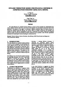
displayed including “building connection”, “filtration”, “dossing pot S1”, “pump S1”, “pump S2”, “3 way valves”, “pressure control S1”, “degasser S1”, “heat exchanger”, “pressure control P1”, “chiller connection”, “degasser P1”, “pump P1” and “dossing pot P1”. It is noteworthy that the schematic excludes two product subsystems, i.e. “control panel” and “structure”. Fifteen informal discussions were carried out with different groups of engineers from the collaborating company to investigate the plant-room design processes and to validate emergent understanding of their engineering operations. Each of these discussions lasted between 15 and 120 minutes. The discussions took place at the collaborating company's main design offices and factories as part of periodic visits and during a week secondment. The experts interviewed included mechanical engineers, design engineers and systems engineers who regularly work on plant-room products.
Methodology
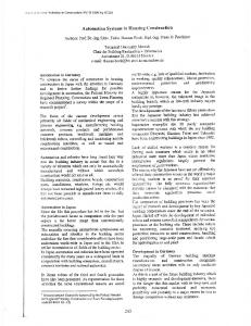
A case study was carried out to determine the suitability of different modularisation tools to support the building design process. Three different tools, namely DSM, MIM and GVI were implemented to modularise a plant-room (see Figure 1). Each tool was evaluated by determining its effectiveness at tackling modular drivers. The methodology of the study involved: 1) collection of information about the product case to be studied; 2) compilation of modular drivers; 3) implementation of three modular tools to the plant-room design; and 4) evaluation of the three tools to establish which of them would best satisfy the modular drivers.
Figure 1: Modular chilled water plant-room (Source: Laing O'Rourke 2016) Collection of product case information: In order to implement the modularisation tools, knowledge about the plant-room product was required. This was acquired through a reverse engineering process, which comprised examination of existing product documentation and discussions with engineers from the collaborating company. Various product documents were examined including product manuals, CAD files, schematics and bills of materials. A simplified version of the product schematic is illustrated in Figure 2. The product schematic illustrates the mechanical characteristics of the plant-room. A total of 14 product sub-systems are
Figure 2: Simplified plant-room schematic Compilation of modular drivers: A list of fifteen modular drivers was produced based on a review of the academic literature [11], [15], [17], and informal discussions with industry experts. Two types of modular drivers were identified: generic and construction specific. Generic modular drivers include technical specification, styling, carry over, product planning, technology evolution, process specification, common unit, manufacturing, separate testability, purchasing, maintenance, product upgrading, and recycling, while construction specific modular divers comprise transportation and architectural restrictions. Implememtation of the three tools: Design Structure Matrix (DSM): A component-based “function” DSM model was developed using the Cambridge Advanced Modeler software 2014 [30]. Two pieces of information were utilised to build the model: material flows and spatial preferences. The former was collected directly from the product schematic (see Figure 2). The latter is based on safety and maintenance information as well as operational preferences and was elicited from engineers in the collaborating company.
34th International Symposium on Automation and Robotics in Construction (ISARC 2017)
Modularisation Identification Matrix (MIM): The MIM model involved mapping the modular drivers against the product sub-systems extracted from the plantroom schematic. Information on the relationships between the modular drivers and product sub-systems was determined during the collection of product information (see section 3) and entered in the MIM model. Generational Variance Index (GVI): As part of work which is not reported in this paper but is part of this project a QFD model was developed for the plant room. The model maps non-functional requirements to functional requirements and then to product sub-systems using QFD1 and QFD2 matrices [5]. The QFD2 matrix which maps the functional requirements to the product sub-systems was used for the generation of the GVI. Information for the matrix was collected from interviews with engineering from the collaborating company. Preliminary evalution: Two engineers in the plantroom design team of the collaborating company were interviewed in March 2017 to evaluate and rank the modular designs emerged from the application of the three tools. The engineers interviewed have 15 and 25 years of experience respectively. Both interviews took place at the collaborating company and lasted for approximately half an hour and an hour respectively. A questionnaire with open ended questions was prepared and used to guide the interviews. The modular designs obtained through the three modularisation tools were also compared against a modularised reference model developed by the collaborating company. The variable used for comparison between the former and the latter is the number of identical “sub-system to sub-system relationships” (SSR) within a distinct module.
4
Case study: plant-room modularisation
This section of the paper presents an application of the three modularisation tools.
Figure 3: Dependency Structure Matrix The DSM model was built using a total of 16 product sub-systems, which were mapped on to themselves capturing the plant-room’s material flows and spatial preferences (see Figure 3). Sub-system to sub-system dependencies were labelled on a scale of 2 to -2, where 2 signifies a required dependency and -2 implies a detrimental relation. The material flows were established from the product mechanical schematic. The spatial preference is based on safety, operational and maintenance considerations. The CAM culturing algorithm was used to cluster sub-systems into modules based on the input dependencies. The partitioning feature was then used to determine the ordering of the modules. As can be seen in Figure 3, seven modules were recommended by the DSM tool with two modules composed by a single product sub-system (i.e. control panel and structure).
4.2 4.1
Dependency Structure Matrix (DSM)
DSM addresses technical specification as a modular driver. It also considers maintenance issues but not robustly. DSM clusters product sub-systems based on their dependencies (see Figure 3). High dependency amongst product sub-systems means that the sub-systems have high functional reliance on each other. Therefore, it would be beneficial if they were clustered together into a module. This would allow the module to hold a section of the product functionalty and address the technical specification.
Modular Identification Matrix (MIM)
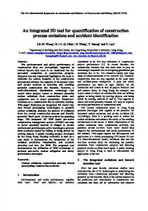
MIM has a more holistic approach to modularity and supports as many modular drivers as a user wants. It also offers a platform for determining how the various modular drivers interact with each another. However, it lacks technical rigor and relies heavily on judgment in determining modules. The MIM tool was applied to map 15 modular drivers against the 16 product sub-systems. A simplified version of the MIM model can be seen in Figure 4.
9
1
1
Techonolgy Push
3
1
Production Process
3
Product Planning
Common Unit
9
Manufacturing
9
Separate Testabiltiy
3
Purchasing
1
Mainatiance
9
Product upgrading
1
Recycling
3
Transportation Architectural
9
9
3
3
3
1
1
9 9
1
1
9 1
9
9
1 1
9
1
1
3
1
9
9
1 9
3
3
3
3
3
3
1
1
1
1
1
1
9
9
9
9
3
3
9
1
1
1
1
9
9
9
9 9
3
9 3
9
9
3
9
9
1
1
9
9
9 3
3
3
9
9
3
9
9 9
Structure
3
4.3 Control panel
Heat exchanger
Dossing pots P1
Pumps P1
Chiller connection
3
Pressure control 1
3
Pressure control P1
3
3
Degasser P1
9
3
1
Filltration
9
Styling Carry over
3 Way-valves
Pumps S2
Dossing-pots 1
9
Degasser 1
Imp
Pumps S1
Modular Drivers Techical spesification
Building connection
34th International Symposium on Automation and Robotics in Construction (ISARC 2017)
9 9
9
Grades 117 195 132 120 195 42 192 111 120 195 120 129 105 96 210 324 M
M1
M1
M1
M1
M2
M2
M3
M3
M4
M4
M4
M5
M5
M5
M6
M7
Figure 4: Modularisation Identification Matrix The tool identifies which modular drivers would influence different product sub-systems. Each modular driver is weighted, depending on its importance in compliance with the collaborating company's operations and views. The importance (I) and modular driver's influence (R) weightings are on a skewed scale, which favours more pressing modular drivers. This approach allows easier identification of stronger driving forces [11]. The values of the skewed scale are 9 (high importance), 3 (medium importance), and 1 (some importance). From the data it is possible to determine which product sub-systems best satisfy the modular drivers and therefore should form modular nucleuses. Modular driver satisfaction grades (MSG) can be calculated as highlighted in equation (1).
Generational Variance Index (GVI)
GVI is a metric tool that approximates the likelihood and potential rework needed for the next product evolution. It directly targets technology evolution as a modular driver. GVI can be used as a standardisation indicator as well as to address common unit as a modular driver. The development of a common unit relates to clustering the product sub-systems, which are least likely to change. As such, it supports the development of a product platform. In this research the GVI model was generated through a modified version of QFD2 for the plant-room [5]. Due to its size, the QFD model was not included in this paper. However, Figure 5 illustrates the general layout and features of the model. The matrix maps functional requirements against product sub-systems in regards to the amount of redesign needed if the functional requirements are to change. GVI is traditionally calculated by equation (2) [21] but in this case study it was calculated by equation (3). The new method to calculate the GVI allows for a more comprehensive insight into determining the risk of redesign by summing the product of the change likelihood (C) and the redesign due to change (R), where ‘x’ is the product sub-system number associated with the GVI value and ‘i’ is the row number associated with the specific functional requirement.
(1) This sums the product of the modular diver’s importance (I) and modular driver's influence” (R), where ‘x’ is the product sub-system number associated with the MSG value and ‘i’ is the row number associated with the specific product sub-system. Product subsystems with higher MSG grades are identified as modular nucleus. The modular nucleuses are Pumps S1, Pumps S2, Chiller pumps, Filtration, Control panel and Structure, with MSGs of 195, 195, 195, 192, 210 and 324 respectively. The remaining product sub-systems are clustered around these modular nucleuses based on engineering judgement and rationale. The nucleuses are marked in grey in Figure 4. The three product subsystems in black stripes in Figure 4 have been clustered clustered using rationale based on satisfaction of the common unit modular driver. As shown in Figure 4 the MIM model has also yielded seven modules. Six modules are based on clustering around a neucleus and one on common unit rationale.
Figure 5: Quality Function Deployment Matrix 2
(2) (3) The GVI values for the plant-room are shown in Table 1. A high GVI value signifies that the product subsystem is likely to require redesign work. A low GVI value means that the product sub-system is less likely to require redesign work and is more suitable for
34th International Symposium on Automation and Robotics in Construction (ISARC 2017)
standardisation. Therefore, product sub-systems with lower GVI values could be clustered to form a module platform as for example module 2 and 3 (M#2 and M#3). As shown in Table 1, developing a modular product platform using GVI has yielded seven modules. Table 1. GVI values and module numbers Product Sub-System Chiller Connection Dossing Pots P1 Dossing Pots S1 Degasser P1
GVI
Degasser S1 Filtration Presure Control P1 Presure controle S1
4.4
Product SubSystem 3 Way-valves
GVI
1
M # 3
9
M # 3
2
3
Control panel
10
6
2
2
Pumps P1
12
5
6
3
14
1
6 7 8
3 2 3
Building Connection Heat Exchager Pump S1 Pump S2
18 26 26
4 1 1
8
3
Structure
40
7
Modular Importance DSM GVI MIM Drivers 1 Technical 6 A J Specification 2 Styling 2 J 3 Carry Over 4 J 4 Product 5 J Planning 5 Technology 4 A J Push 6 Production 4 J Process 7 Common Unit 6 A J 8 Manufacturing 6 J 9 Separate 4 J Testing 10 Purchasing 3 J 11 Maintenance 5 J J 12 Product 3 J Upgrading 13 Recycling 4 J 14 Transportation 5 J 15 Architectural 6 J A: Algorithmic process; J: Judgement-based process
Modularisation results and drivers
The implementation of the three tools resulted in as many modular designs. Table 2 shows the modular designs obtained through DSM, MIM, and GVI as well as the modularised reference model proposed by the collaborating company.
3 Way-valves
Pump S1
Dossing-pots S1
Pump S2
Degasser 1
Pressure Control S1
Pumps P1
Chiller Connections
Dossing Pots P1
Pressure Control P1
Degasser P1
Heat Exchanger
Building Connection
Filtration
Control Panel
Structure
Table 2. Modular plant-room designs
D S M M I M G V I R e f
Table 3. Tools fulfilment of modular drivers
1
1
2
2
3
3
5
4
5
4
5
4
1
2
6
7
2
2
1
1
1
3
5
5
5
4
4
4
1
3
6
7
3
1
2
1
3
3
5
3
3
3
3
4
2
5
6
7
2
2
1
1
1
3
4
4
4
5
5
4
1
3
6
-
The three tools approach modularisation from different perspectives and each addresses a set of modular drivers, see Table 3. It is noteworthy that in Table 3 the fifteen modular drivers are prioritised according to their relevance to the collaborating company’s operations for plant-rooms. In addition a distinction has been made to indicate of a tool allows to achieve a modular solution through an algorithmic (A) or a judgment-based process (J).
5
Evaluation
The three modular plant-room designs were ranked by two engineers from the collaborating company in terms of functional dependency between sub-systems. Less consideration was given to the other modular drivers. The design produced through DSM and MIM were ranked first and second followed by that produced through GVI. DSM and MIM yielded agreeable results from the perspective of the plant-room design engineering team. In particular, the DSM result was found to be the closest to the engineers’ modularisation mindset. This is because the approach to modularisation of the design engineering team is based on complimenting product functionality. These views highlight that functionally dependent sub-systems should be clustered together and other influencing considerations are of secondary importance. These views on functional dependence are in line with how DSM operates. While MIM addresses functional considerations, it does not address functionality as comprehensively as DSM. MIM also takes on other modular drivers. Further, GVI does not address functional considerationa at all and is therefore regarded as unacceptable for the purpose of designing plant-rooms. Sub-system to sub-system relationships (SSR) were used to evaluate the three designs by comparing them to the company’s reference model. The number of identical SSR within a distinct module indicates the degree of similarity between the result of a modular tool and the reference model. The design with the highest number of
34th International Symposium on Automation and Robotics in Construction (ISARC 2017)
identical SSR to the reference model is deemed closer to the design put forward by the collaborating company. The results from this investigation indicate that the MIM based design has 10 out of 13 SSR identical to the reference model, DSM has 5 and GVI has only 3. This evaluation suggests that the MIM based design is distinctively closer to the company design compared to those produced with DSM and GVI.
Limitations: A drawback of this preliminary evaluation is that it only considers the perspective of the plant-room design team. In this respect the study needs to incorporate the perspectives of other engineering teams such as those involved in quality control, manufacturing and architecture. These different teams are likely to provide different point of views.
7 6
Discussion
This research was undertaken to investigate how three modularionsation tools can be used to support the building design process. The research has distinguished the three tools in terms of the modular drivers they tackle and the process used to produce a modular solution, namely algorithmic or judgement-based process. The former refers to the ability of a tool to handle modular drivers from a technical perspective, while the latter to its reliance on subjective considerations. The modular designs produced through the three tools were first ranked by experts in the collaborating company and then their similarity to the reference model was assessed based on connectivity information. The design engineers valued most the modular solution obtained through the DSM tool, whereas the comparison to the reference model showed the MIM tool produced the solution that is closer to the modularisation direction currently pursued by the collaborating company. This can be explained as follows. The DSM based solution best satisfies the modularisation objectives directly relevant to the role covered by the design engneers in the organisation, i.e. functional dependency between the product sub-systems. On the other hand the MIM tool has allowed to find the best trade-off between multiple modular drivers and taking into account interdisciplinary considerations. This research suggests that neither considering multiple modular drivers in a subjective way as in MIM nor accounting for isolated modular drivers in a technical manner as in DSM and GVI is an optional solution. On their own, each of these tools exhibited limitations and the problem of tackling multiple modular drivers with a technical solution is not addressed. Multiple tools need to be considered to capture the full complexity of a modularisation problem. This research recommends to docus on the integration of complementary tools to generate more effective modular solutions. MIM should be utilised as the primary tool for modular construction management because of its ability to capture multiple modular drivers. It enables the gathering of issues arising from multiple disciplines in one system. The application of tools such as DSM and GVI should be considered for more robust solutions in respect to their individual modular drivers.
Conclusion
This research compared three modularisation tools applied to a plant-room design process. The three tools were evaluated by determining their effectiveness in addressing modular drivers. Fifteen modular drivers were identified and prioritied. Each of the three tools addresses a different set of modular drivers and with a process that is either algorithmic or judgement based. MIM offers a more holistic approach to modularity and supports a wider range of modular drivers. However, it lacks technical rigor in determining modules. DSM and GVI provide technical solutions but each of them focuses on a specific modular drivers, namely DSM on technical specification and GVI on common unit and technology evolution. This paper concludes that DSM, MIM and GVI should be used in an integrated manner to tackle multiple modular drivers. As such, they would provide a more effective modularisation strategy in construction.
8
Acknowledgment
The authors would like to acknowledge the support for this research of the EPSRC and Laing O'Rourke through industrial CASE Award N:1589417.
9
Reference
[1] Marchesi M., Kim S. G., and Matt D. T. Application of the axiomatic design approach to the design of architectural systems: a literature review. In Proceedings of ICAD pp. 27-28. 2013. [2] Höök M. Customer value in lean prefabrication of housing considering both construction and manufacturing. Proceedings of the 14th Annual Conference of the International Group for Lean Construction, Santiago de Chile. 2006. [3] Borjesson F. and Hölttä-Otto K. A module generation algorithm for product architecture based on component interactions and strategic drivers. Research in Engineering Design, 25(1), pp.31-51. 2014. [4] Gilbert III L. R., Farid A. M. and Omar, M. An axiomatic design based approach to civil engineering. In Proceedings of the 2nd International Workshop on Design in Civil and Environmental Engineering pp. 30-38. 2013.
34th International Symposium on Automation and Robotics in Construction (ISARC 2017)
[5] Wee T. P. Y., Aurisicchio M., and Starzyk I. The application of Quality Functional Deployment to modular offsite construction products. International Conference for Engineering Design (ICED), Vancouver, Canada, 2017. (Accepted). [6] Gann, D. M. Construction as a manufacturing process? Similarities and differences between industrialized housing and car production in Japan. Construction Management & Economics, 14(5), pp. 437-450. 1996. [7] Lawson R. M., Ogden R. G. and Bergin R. Application of modular construction in high-rise buildings. Journal of architectural engineering. pp. 148-154. 2012. [8] Suh E. S., De Weck O. L., and Chang D. Flexible product platforms: framework and case study. Research in Engineering Design, 18(2), pp 67-89. 2007. [9] Kreng V.B. and Lee T.P. QFD-based modular product design with linear integer programming—a case study. Journal of Engineering Design, 15(3), pp.261-284. 2004. [10] Kohlhase N., and Birkhofer H. Development of modular structures: the prerequisite for successful modular products. Journal of Engeering Design, 7(3), pp 279-291. 1996. [11] Erixon G. Modular function development mfd, support for good product structure creation. In DS 53: Proc. of the 2nd WDK Workshop on Product Structuring 1996, Delft University of Technology, the Netherlands, 03.-04.06. 1996. [12] You Z. H., and Smith S. A multi-objective modular design method for creating highly distinct independent modules. Research in Engineering Design, 27(2), pp.179-191. 2016. [13] Koh E. C., Förg A., Kreimeyer M., and Lienkamp M. Using engineering change forecast to prioritise component modularisation. Research in Engineering Design, 26(4), pp. 337-353. 2015. [14] Emmatty F. J. and Sarmah S. P. Modular product development through platform-based design and DFMA. Journal of Engineering Design, 23(9), pp. 696-714. 2012. [15] Hölttä-Otto K. Modular product platform design. Helsinki University of Technology. 2005. [16] Ulrich K. T. and Eppinger, S. D. Product design and development. New York: MacGraw-Hill. 2008. [17] Borjesson F. A systematic qualitative comparison of five approaches to modularity. 11th international design conference, design 2010, Dubrovnik, Croatia, May 17–20, vol 2. 2010. [18] Sellgren U., and Andersson S. "The Concept of Functional Surfaces as Carriers of Interactive Properties", International Conference on Engineering Design (ICED 05), Melbourne. 2005.
[19] Marchesi M., and Ferrarato, I. A. Addressing the adaptive customization of timber prefabricated housing through axiomatic design. Procedia CIRP, 34, pp. 199-205. 2015. [20] Jung S., and Simpson T. W. An integrated approach to product family redesign using commonality and variety metrics. Research in Engineering Design, 27(4), pp. 391-412. 2016. [21] Simpson T. W., Bobuk A., Slingerland L. A., Brennan S., Logan, D., and Reichard K. From user requirements to commonality specifications: an integrated approach to product family design. Research in Engineering Design, 23(2), pp 141-153. 2012. [22] Meyer M. H., and Lehnerd A. P. The power of product platforms. Simon and Schuster. 1997. [23] Pan W., Gibb A. G. and Dainty, A. R. Leading UK housebuilders' utilization of offsite construction methods. Building Research & Information,36 (1), pp. 56-67. 2008. [24] Simpson T. W. Product platform design and customization: Status and promise. AI EDAM: Artificial Intelligence for Engineering Design, Analysis and Manufacturing, 18(01), pp. 3-20. 2004. [25] Cuperus Y. Mass customization in housing an open building/lean construction study. In Proceedings of Dense Living Urban Structures International Conference on Open Building, Hong Kong, China Vol. 2326, pp. 113. 2003. [26] Jensen P., Olofsson T., Smiding E., and Gerth, R. Developing Products in Product Platforms in the AEC Industry. In Computing in Civil and Building Engineering pp. 1062-1069. ASCE. 2014. [27] Veenstra V.S., Halman J.I. and Voordijk J.T. A methodology for developing product platforms in the specific setting of the housebuilding industry. Research in engineering design, 17(3), pp.157-173. 2006 [28] Jiao J. R., Simpson T. W., and Siddique, Z. Product family design and platform-based product development: a state-of-the-art review. Journal of Intelligent Manufacturing, 18(1), pp 5-29. 2007. [29] Martin M.V. and Ishii K. Design for variety: developing standardized and modularised product platform architectures. Research in engineering design, 13, pp. 213–235. 2002 [30] Cambridge, E. D. C. Cambridge Advanced Modeller. 2016.