simple association schemes perform. Our results show the critical impact of the association rules on system performance and shows the interplay of the different ...
Joint Channel Allocation and User Association for Heterogeneous Wireless Cellular Networks Dariush Fooladivanda, Ashraf Al Daoud and Catherine Rosenberg Department of Electrical and Computer Engineering University of Waterloo, Canada Email:{dfooladi, aaldaoud, cath}@ecemail.uwaterloo.ca
Abstract—We study the engineering of heterogeneous cellular networks composed of a macrocell and some picocells by investigating the interplay of different network processes and parameters such as channel allocation, user association and reuse pattern (to control inter-cell interference between picocells). We formulate a joint association, channel allocation, and intercell interference management problem that relies on very few assumptions. This problem turns out to be an Integer Non-Linear program that is NP-hard. However, its structure is such that we can solve it exactly for relatively large size systems. We use optimal solutions as benchmarks to understand how different simple association schemes perform. Our results show the critical impact of the association rules on system performance and shows the interplay of the different processes and parameters. We believe that these insights will help design online association schemes in the future.
I. I NTRODUCTION Current cellular wireless technologies are mainly based on homogeneous networks. In such networks, base stations follow a carefully planned layout and are largely identical in terms of power levels, antenna configurations, backhaul capacities, etc. Base stations are carefully configured to optimize coverage, minimize interference with other base stations and ensure a roughly equivalent number of users in each cell. While cell splitting can be used to accommodate growing traffic demands, this can be problematic in dense urban environments. Furthermore, a typical modern base station in isolation, employing advanced signal processing, modulation and coding techniques, is now near the Shannon limit of theoretical performance in terms of spectral efficiency. Hence, to be able to support the anticipated high volumes of traffic in the future, cellular operators will have to deploy a mix of network technologies [1]. The LTE-Advanced standard for example proposes improvement to network-wide spectral efficiency by employing a mix of macro, pico, femto and relay basestations [2], [3]. The context of this study is heterogeneous networks (Hetnets) and their engineering and planning. Its purpose is twofold: First, it is to show the interplay between the many options that a cellular operator has to choose from when engineering a Hetnet in a given region, and second, to show the importance of understanding some of the tradeoffs at hand. As our study is designed for the engineering phase of Hetnets (as a step preceding the operational phase) it can be seen as a first order study of the importance of some deployment
decisions. More precisely, at the time of deployment, the operator needs to take many decisions that are functions of the predicted profile of the user population in the region under consideration (e.g., user distribution, etc.) and the level of service to offer under nominal conditions. Decisions to be taken should include the following four processes: 1) Placement of the network components to be deployed (types and quantities): Examples include, but are not limited to, the deployment of femto/pico access points, distributed antennas, and wired relays. Each of these technologies has its own operational characteristics (e.g., transmitting power, rates, etc.) The operator will revisit this decision from time to time to add new components based on demands and measured performances. 2) Interference management and resource allocation scheme: In homogeneous cellular networks, a licensed frequency band is shared among the different cells using some frequency planning algorithm. Inherent to the deployment of Hetnets is the challenge of intercell interference management and resource allocation. Multiple options exist for managing interference and allocating resources in a Hetnet [4], [5] and selecting the right option is a very hard problem. 3) User association rule: An association policy defines a set of rules for assigning users to the different available base stations in the Hetnet. This includes decisions for users who are covered by more than one base station. A decision to associate a user with a certain base station will affect the throughput seen by that user. 4) User scheduling policy: User throughput is a function of the number of users associated with the same base station as well as the user scheduling policy implemented by the base station and the allocated resource. Hence, the choice of a scheduling policy will impact the system performance. There is clearly a complex interplay between the different decisions an operator needs to take into account during the deployment phase. It is thus important to perform studies that consider all these four processes; namely placement, interference management and resource allocation scheme, association and scheduling. In this paper, we define precisely the Hetnet that we study in terms of these processes and we formulate a “one-shot” joint association, resource allocation,
and inter-cell interference management problem that relies on very few assumptions. We call the problem “one-shot” because we assume that, given some input variables (defined later) we compute at the same time all the parameters of our optimal configuration. This problem turns out to be an Integer Non-Linear program that is NP-hard. However, its structure is such that we can solve it exactly for relatively large size systems. We use these results as a benchmark to understand how different simple association schemes perform. Our results show the critical impact of the association rules and the interplay of the different processes and parameters. We believe that these insights will help design online schemes in the future that take the dynamics of the system into account. In order to present our contributions in more details, we need to describe precisely our system. We consider a dense urban region covered by one macrocell and partially covered by X identical short range picocells. We assume that the cellular network operator has an estimate of the users’ distribution in the region at peak hour time. We assume that the macrocell and the picocells belong to the same operator and they are operated in the same licensed frequency band using an OFDM system. Namely, the Hetnet as a whole is allocated a frequency band that is divided into M subchannels (we will use the term channels and subchannels interchangeably in the following). We adopt a fixed channel allocation strategy between the macrocell and the picocells so that K channels are dedicated to the picocells (and M − K channels to the macrocell), hence there is no interference between the macrocell and the set of picocells. The K channels are equally divided among the picocells based on a given reuse factor u. By using a reuse factor, we effectively do frequency planning for the picocells within the macrocell and by choosing u carefully, the operator can keep the inter-pico cell interference manageable. Clearly by taking u large we can avoid interference altogether, but we allow much less channel reuse, hence the choice of u will impact performance. In our study, both u and K are parameters that we want to configure. As mentioned earlier, we are going to formulate a “one-shot” optimization problem where we will configure at once the values of K, u and the optimal association for each user. We assume that a user can only associate with one base-station at a given time. We focus on the downlink and assume that the macrocell and all the picocells within it use the same scheduling policy based on maximizing the minimum user throughput. Note that during the operating phase of the system, the different parameters are configured at different time scales. Whenever X changes or N the number of users varies significantly, K and u will be recomputed while the association is a dynamic process that is called whenever a user comes and goes. Our study can be used to provide an upper bound on the performance that can be achieved since we are optimizing everything at once. The closest work to ours is [6] in which the authors consider the effect of user association on the network’s throughput for a given fixed partitioning of resources between the macrocell and some picocells (there is no optimization made on the resource allocation). A simple association rule called “Range
Extension” is proposed, and the authors show by simulation that it can improve the network’s throughput as compared to another association rule based on SINR (Signal to Interference and Noise Ratio). In “Range Extension”, users associate with the base station with the minimum path loss rather than the conventional rule in which users associate with the base station with the maximum downlink SINR. In [7], the performances of “Range Extension” and the conventional association rule are compared under a specific channel allocation in which the resources are equally divided between the macrocell and the picocells. The authors show via simulation that the number of users served by picocells is already large enough with the conventional user association rule, and “Range Extension” does not improve users’ throughput significantly. In [8], Tongwei et al. propose a new user association rule called “Based on Queue (BQ)” that associates more users with the picocells, and they compare its performance under two different resource allocation schemes called “Overlap ICIC” and “Non-overlap ICIC”. In “Overlap ICIC”, macrocell nodes use half of the available frequency while picocells can use the entire frequency band. In “Nonoverlap ICIC”, the available bandwidth is equally divided between macrocells and the picocells. Finally, it is shown via simulation that the new scheme works better than “Range Extension” and the conventional user association rule. Our contributions are: 1) We formulate a one-shot joint user association, channel allocation, and reuse pattern optimization problem for a heterogenous network that consists of one macrocell and many picocells under a fixed channel allocation strategy. We make no restricting assumptions on the channel gains, the rate functions and the overlapping of the picocells. In spite of the fact that this problem is an Integer Non Linear problem, we are able to solve it exactly numerically for relatively large systems. 2) We use the numerical results as a benchmark to quantify how well 3 simple association rules perform including the one proposed in [6]. Another contribution is to show that u = 1 is almost always the best solution. 3) We study the impact of K, the number of channels allocated to the pool of picocells and show how different association rules perform when K is not computed optimally but given. Altogether, our study emphasizes the importance of looking at the engineering problem in its globality as opposed to looking at each process independently. The paper is organized as follows: The problem setup and formulation of the performance optimization problem is introduced in Section II. In Section III, the 3 simple association rules that we will study are introduced. Numerical results are provided in Section IV. The conclusions are given in Section V. II. P ROBLEM S ETUP AND F ORMULATION Consider an OFDM system composed of a macrocell (cell 0) that is overlaid by X picocells (cells j = 1, · · · , X). Assume
that there are M subchannels available on the downlink to serve N users in the system where each subchannel is of bandwidth b. Assume also that each base station assigns equal power to all of its subchannels where P0 denotes the transmission power of the macrocell base station and P denotes the transmission power of each picocell base station. Let γij denote the SINR at the location of user i from base station j and rij = f (γij ) denote the rate in bps/Hz assigned to the user. Here, f (·) is a rate function that maps the SINR to the corresponding rate. The deployed Modulation and Coding Scheme (MCS) defines f (·). This function is typically a given discrete step function ( [12], [13], and [14]). We adopt a fixed channel allocation strategy between the macrocell and the picocells so that out of the M channels available K channels are allocated to the picocells and M −K channels are left to the macrocell. The K channels are equally divided among the picocells based on a given reuse factor u where 1 ≤ u ≤ X. We choose u so that if a channel is reserved for the exclusive use of the picocells, it cannot be used at the same time by more than d X u e picocells. Given a reuse factor u, there are in general multiple possible reuse patterns. Let P(u) be the set of such reuse patterns. By using a reuse factor and a reuse pattern, we effectively do frequency planning for the picocells within the macrocell. In our system there is no co-channel interference for macrocell users (i.e, γi0 is effectively an SNR) while picocell users may suffer from co-channel interference and γij is a function of both u and the reuse pattern. We assume that each user can be associated with only one cell. In this respect, let xij =P1 if user i is associated with cell j and 0 otherwise. Thus, j∈B xij = 1 for all i where B denotes the set of base stations. We assume that the macrocell and the picocells use the same user scheduling policy to maximize the minimum throughput of users associated with any cell. Thus, for a given cell j, all users associated with the cell will receive the same rate. Let λj denote such rate. To compute λj , let Bj denote the bandwidth allocated to cell j (i.e., Bj = nj b where nj is the number of channels allocated to j and b is the width in Hz of a channel) and let Aj be the set of users associated with cell j. For each user i ∈ Aj , λj satisfies: αi Bj f (γij )
= λj , ∀i ∈ Aj , X αi = 1
(1) (2)
i∈Aj
where αi is the proportion of time that user i is scheduled on the downlink. Hence, λj is given by: λj = P
Bj
1 i∈Aj f (γ j ) i
.
(3)
In this study, K, u, and {xij } are the parameters we aim to configure. Our problem can be formulated as follows: Given X, N , the positions of the base stations, the positions of the N users, the SINR of each user, the rate function, and a set of reuse patterns P(u), compute K, u and xij so as to maximize
the value of λ: P0 :
max
λ
Kb PN
≥ λ,
K,(u,P(u)),{xij }
u
xij i=1 r j i
(4a) ∀j ∈ {1, · · · , X}
(M − K)b PN xi0 ≥ λ
(4b) (4c)
i=1 ri0
X X
∀i ∈ I
xij =1,
j=0 rij =
f (γij ),
xij ∈ {0, 1},
∀i ∈ I ∀i ∈ I
(4d)
∀j ∈ J ∀j ∈ J
(4e) (4f)
K ∈ {0, 1, · · · , M }
(4g)
u ∈ U , P(u) ∈ P ,
(4h)
where I = {1, · · · , N } and J = {0, 1, · · · , X} denote the set of users and the set of base stations, respectively. The effect of the reuse pattern P(u) is implicit in γij since the SINR depends on the reuse pattern implemented. Such dependence is not indicated explicitly in the problem to reduce notational burden on the reader. Problem P0 is a non-linear integer program which is hard to solve. However, if K and (u, P(u)) are fixed, a linear integer program in {xi,j } can be formulated. Namely, given a value of K = K0 ∈ {0, 1, · · · , M } and given a reuse factor and pattern (u0 , P(u0 )), problem P0 (K0 , u0 , P(u0 )) can be written in the following form: P1 (K0 , u0 , P(u0 )) : min
ζ
{xij }
u0
xij i=1 r j i
(5a)
PN
K0 b PN xi0
≤ ζ,
∀j ∈ {1, · · · , X} (5b)
i=1 ri0
≤ζ (M − K0 )b X X xij =1, j=0 rij =
f (γij ),
xij ∈ {0, 1},
(5c) ∀i ∈ I ∀i ∈ I
∀i ∈ I
∀j ∈ J ∀j ∈ J
(5d) (5e) (5f)
where all rij ’s can be computed beforehand and used as inputs to the optimization problem. A solution for P0 can be obtained by solving P1 (K0 , u0 , P(u0 )) for all possible values of K0 and (u0 , P(u0 )) and then selecting the largest solution. In particular, define the solution for P1 for a given K, u, and P(u) as λ?1 (K, u, P(u)). Hence, the solution for P0 can be obtained by solving max
{K,u,P(u)}
{λ?1 (K, u, P(u))} .
(6)
Still, this approach can lead to an exhaustive set of problems to solve. Namely, assume that each user can hear at least two
base stations, then P1 will have 2 × N variables; and it needs to be solved M × |P| times where P denotes the set of reuse patterns. However, we were able to solve P0 in this manner for a system of 16 picocells placed on a grid with 350 users. We consider the cases u = 1, 2, 3, 4 with one reuse pattern for each reuse factor. Those results helped us obtain some engineering insights of the performance of a set of existing and proposed association rules as will be shown in the sequel. In the next section, we describe those rules and provide comparisons with the optimal association as obtained by solving P0 . III. S IMPLE U SER A SSOCIATION RULES The following user association rules are considered in our study: 1) SINR-based: A user i associates with base station j ? = arg maxj=0,1,··· ,X {γij }. This is the association rule used today in homogeneous networks. This rule is known not to perform well in a heterogeneous setting because a macrocell base station usually transmits at a higher power level than picocell base stations. Hence, with this association rule, most of the users will have a better SINR from the macrocell than any of the picocells and will associate with the macrocell. This rule is thus not favorable from a channel reuse standpoint. 2) Picocell First: A user i associates with the picocell? base station j ? = arg maxj=1,··· ,X {γij } as long as γij > β where β is a parameter to tune. The motivation behind this rule is the premise of heterogeneous networks that try to bring base stations closer to the users to improve their rates. In this respect, the rule tends to favor association with the picocells. 3) Range Extension [6]: A user i associates with the base station j ? = arg minj=0,1,··· ,X {δij } where δij is the path loss from base station of cell j to user i. This is another rule to favor association with picocells. Simplicity of these rules comes at the expense of load balancing among base stations. The optimal association takes load balancing into account by associating users with base stations such that the minimum throughput is maximized. For each of 3 rules, we can compute beforehand what will be the values of xij for all users i if we fix a reuse factor u0 and a reuse pattern P(u0 ). In that case, the problem P0 reduces to the following problem that computes the value of K given {xij } and the reuse factor and reuse pattern (u0 , P(u0 )): P2 : max λ
(7a)
{K}
u0
Kb PN
xij i=1 r j i
≥ λ,
∀j ∈ {1, · · · , X}
(M − K)b PN xi0 ≥ λ
(7b) (7c)
i=1 ri0
rij = f (γij ),
∀i ∈ I
∀j ∈ J
(7d)
K ∈ {0, 1, · · · , M }
(7e)
u0 ∈ U , P(u0 ) ∈ P .
(7f)
TABLE I R EUSE FACTORS AND CORRESPONDING REUSE PATTERNS USED FOR THE SECOND CONFIGURATION IN F IGURE 1 reuse factor 2 3 4
Co-channel picocells {1, 3, 5, 6}, {2, 4, 7} {1, 4, 7}, {2, 5}, {3, 6} {1, 5}, {2, 6}, {3, 7}, {4}
Namely, we solve P2 for different reuse patterns (u, P(u)) and then select the largest solution. Let’s define the solution of P2 for a given u and P(u) as λ?2 (u, P(u)). Hence, the solution for P2 is given by max {λ?2 (u, P(u))} .
{u,P(u)}
(8)
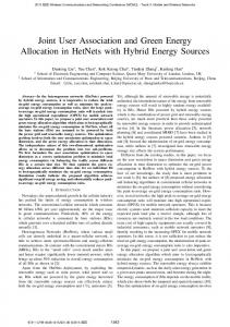
We are now ready to obtain results on the joint optimal association, resource allocation and reuse factor/pattern and to compare them with the cases where the association rule is given. Note that while P0 jointly optimizes the association, the reuse pattern/factor and the resource allocation parameter K, and P2 jointly optimizes the reuse pattern/factor and the resource allocation parameter K for a given association, we can also easily use a version of P0 to optimize the association given a reuse pattern/factor and the resource allocation parameter K. In that case, the optimal association will perform load balancing, and mitigate interference and resource availability at best as possible. IV. N UMERICAL R ESULTS We consider a system composed of a macrocell (cell 0) and X picocells (cells j = 1, · · · , X). It is assumed that the macrocell covers a square area of length L = 1000 m. We consider two different configurations. In configuration 1, there are X =√16 picocells located inside the square on a grid of size √ X × X, and in configuration 2 there are X = 7 picocells located in the square as shown in Fig. 1. The number of subchannels allocated to the system is taken to be 100, each of bandwidth b = 180kHz. In this study, we consider only reuse patterns of the type (uh , uv ) where uh and uv define, respectively, the horizontal and vertical distance (uh √LX , uv √LX ) of the closest picocell base station that can use the same channel subset. Thus, each picocell is granted a number of channels K u , where u = uh × uv . For configuration 1, the set of reuse factors is U = {1, 2, 3, 4}, and the set of reuse patterns is P = {1 × 1 , 1 × 2 , 1 × 3 , 2 × 2}. For configuration 2, the set of reuse factors is U = {1, 2, 3, 4}, and the reuse patterns that we considered are shown in Table I. In both configurations, some users could “hear” (i.e., get an SINR greater than the SINR threshold for the minimum rate in the deployed Modulation and Coding Scheme (MCS)) more than one picocell base station beside the macrocell base station. We use a SINR model that accounts for path loss and slow fading [9]. Path losses are computed based on a typical LTE system [10] and slow fading is modeled by log-normal shadowing with mean zero and standard deviation 8 dB. The
Configuration 2
Configuration 1
is r = θe` =
Macro Base sation
Macro Base sation Pico Base station
Fig. 1.
Hotspots
Pico Base station
Picocell locations for Configuration 1 and Configuration 2.
TABLE II P HYSICAL L AYER PARAMETERS Noise Power Ppico Carrier Frequency BS Cable Loss Penetration Loss
−110 dBm 25 dBm 2 GHz 6 dB 20 dB
Cell Length Pmacro Channel Bandwidth User Noise Figure Shadowing s.d.
1000 m 43 dBm 180 KHz 9 dB 8 dB
SINR of user i at distance dji from base station j = 1, · · · , X (picocells) is computed by the formula SIN Rij (dji ) =
P G δ j (dj ) P j i i h h N0 + h∈Ij P Gh δi (di )
(9)
where Ij is the set of picocell base stations (not including j) that use the same channel set as j, P is the transmitting power of a picocell base station, N0 is the noise power, Gj is a factor which accounts for transmitter/receiver gains and equipment losses. Path loss for picocells is computed using the formula δij (dji ) = 140.7 + 36.7 log10 (dji /1000), dji ≥ 10m . Since there is no interference for the macrocell, the SNR of user i at distance d0i from the macrocell base station is computed using: SN Ri0 (d0i ) =
P0 G0 δi0 (d0i ) N0
(10)
where P0 is the transmitting power of the macrocell base station, G0 is a factor which accounts for transmitter/receiver gains and equipment losses. Path loss for the macrocell is computed using δij (d0i ) = 128 + 37.6 log10 (d0i /1000), d0i ≥ 35m . The physical layer parameters are shown in Table II. The last two lines in the table are used to compute Gj and G0 in (9) and (10), respectively [9]. We assume that the system uses adaptive modulation with discrete rates. Table III taken from [11], [12], [13], and [14] gives us the mapping between the SINR and the efficiency e for the modulation and coding scheme for LTE. In this table, there are 15 levels, let ` be such a level. Hence the bit rate seen by a user that has a SINR between level ` and level ` + 1
SCofdm SYofdm e` . Tsubframe
(11)
where e` is the efficiency (bits/symbol) of the corresponding level `, θ is a fix parameter that depends on the system configuration, SCofdm is the number of data subcarriers per subchannel bandwidth, SYofdm is the number of OFDM symbols per subframe, and Tsubframe is the frame duration in time units. For example, in [11], the values of SCofdm , SYofdm , Tsubframe , and sub-channel bandwidth are 12, 11, 1ms, and 180KHz, respectively. In this study, we normalize the rates to θ for simplicity, since this normalization does not affect the results. Since we are using a discrete rate model (adaptive modulation), we need to consider a minimum SINR threshold for the “Range Extension” association rule; otherwise a user could associate with a base station while its SINR is less than the minimum SINR threshold of the corresponding MCS and hence it will not get any rate. In the following numerical results, we are considering the same value (in dB) for the SINR threshold of “Range Extension” and β for “Picocell First”. To compare the performance of the three association rules with the optimal solution, two configurations are considered as shown in Fig. 1, and based on these configurations we have defined 2 scenarios (in each of them, all base stations use the MCS given in Table III). Scenario 1: In this scenario, we use Configuration 1. There are N = 350 uniformly distributed users. Scenario 2: In this scenario, we use Configuration 2. There are 150 uniformly distributed users. In addition to those 150 users, there are 200 users distributed uniformly in two hotspots shown in Figure 1. Hence, in this scenario, N = 350. For each scenario and each reuse factor u, we computed the max-min rate for each scheme for at least 10 realizations. For each realization, N users are placed at random in the region based on the distribution described for the scenario at hand, and then the users’ rates are computed. We use AMPL (the commercial software “A Modeling Language for Mathematical Programming”) and CPLEX [15] to compute exact results for P0 and P2 (i.e., when an association rule is fixed). We show in the following figures a typical realization. The max-min rate of the system is shown in Figure 2 (without shadowing) and Figure 3 (with shadowing) as a function of the reuse factor u for scenario 1, and in Figures 4 (without shadowing) and 5 (with shadowing) for scenario 2. In these scenarios, we are comparing the performance of the joint optimization of the association and the channel allocation with the performance of the simple association rules when K is computed optimally for the simple rules. For each scenario, we selected the value of β that gave the highest possible max-min rate (for the optimal association) over the range of u that we consider, i.e., β = −2.6 dB for scenario 1 and β = 11.8 dB for scenario 2. For each association rule, the curve shows the highest max-min rate over all values of K for a given u. The results show that “Picocell First” and “Range Extension” are performing relatively well (but not very well in the case with shadowing) for a wide range
TABLE III M ODULATION AND C ODING S CHEMES -LTE SINR thresholds (in dB) Efficiency (in bits/symbol)
-6.5 0.15
-4 0.23
-2.6 0.38
-1 0.60
1 0.88
3 1.18
6.6 1.48
10 1.91
11.4 2.41
11.8 2.73
13 3.32
13.8 3.9
15.6 4.52
16.8 5.12
17.6 5.55
of values of u. In the mean time, “Current Practice” (i.e., the SINR based association) does not perform well especially in scenario 1 as can be seen in Figure 2 and Figure 3. Moreover, the results show that the performance of the simple association rules depends on the network topology, the reuse factor, the users’ distribution, and the threshold β. Shadowing is another factor that can affect the performance of the simple association rules significantly. For both scenarios the reuse factor u = 1 is optimal which means that when jointly optimizing the resource allocation and the association, there is enough degrees of freedom to allow potential significant interference among pico cells (by allocating enough channels to the picocells). Note that selecting a higher reuse factor has a significant negative impact on the performance especially in scenario 1. Altogether, the above results show that no simple association rule performs very well under all scenarios even when K is chosen optimally and this is because none of these associations take load balancing into account. The reality will be even grimmer since in general a value of K will not be recomputed too often and then fixed association rules might be very sub-optimal depending on the value of K. This is what we want to show now. The performance of the system for reuse factor u = 1 (optimal reuse) is shown as a function of K, the number of channels allocated to the pool of picocells, in Figure 6 and Figure 7 for scenario 1, and in Figure 8 and Figure 9 for scenario 2 for the optimal association and the simple rules. For each value of K, we compute the optimal association and its corresponding max-min rate and for each simple association rule, we compute the max-min rate. These figures show that “Picocell First” and “Range Extension” often perform much better than “Current Practice” though not well enough (as compared to the optimal association) on a large range of values of K to consider the problem of user association solved. In fact, we believe that much more work is needed in this area to design simple and efficient association rules. The results show that in the context of resource allocation if the number of sub-channels allocated to picocells is close to the optimal channel allocation and β is chosen properly, then “Picocell First” and “Range Extension” perform relatively well. However, in some scenarios, there is still a relatively large difference between the max-min rate of the optimal association and the max-min rate of the simple rules. Moreover, the results in Figure 6 to Figure 9 show that in the context of resource allocation the optimal channel allocation is different for different user association schemes.
Fig. 2. Scenario 1 : Max-min rate as a function of u for a system without log-normal shadowing, and for β = −2.6 dB.
Fig. 3. Scenario 1 : Max-min rate as a function of u for a system with log-normal shadowing, and for β = −2.6 dB.
Fig. 4. Scenario 2: Max-min rate as a function of u for a system without log-normal shadowing, and for β = 11.8 dB.
Fig. 5. Scenario 2: Max-min rate as a function of u for a system with log-normal shadowing, and for β = 11.8 dB.
V. C ONCLUSIONS
Fig. 6. Scenario 1 : Max-min rate as a function of K for reuse factor u = 1, and for β = −2.6 dB without log-normal shadowing.
Fig. 7. Scenario 1 : Max-min rate as a function of K for reuse factor u = 1, and for β = −2.6 dB with log-normal shadowing.
Fig. 8. Scenario 2 : Max-min rate as a function of K for reuse factor u = 1, and for β = 11.8 dB without log-normal shadowing.
Fig. 9. Scenario 2 : Max-min rate as a function of K for reuse factor u = 1, and for β = 11.8 dB with log-normal shadowing.
In this study, we have formulated a joint optimization problem of user association, channel allocation and reuse pattern selection for a heterogenous network that consists of a macrocell and a certain number of picocells. We have first computed the optimal solution to this problem, then we have used the solution as a benchmark for evaluating simple user association rules. We have shown the significant impact of both the association rule and of the reuse pattern on the performance of the Hetnet. In particular, we have shown that rules which favor associating users with the picocells (e.g. “Picocell First” and “Range Extension”) yield significantly better performance results than “Current Practice” if their corresponding parameters, β for “Picocell First” and minimum hearing threshold for “Range Extension”, are chosen appropriately. Moreover, our numerical results show that selecting an aggressive reuse factor u (i.e., u = 1) can lead to significant gains in throughput. Furthermore, we have shown that no simple association rule perform well enough even if the channel allocation K is close to the optimal channel allocation. Because of that, much more work is needed in this area to design simple and efficient association rules. Note that all these results have been obtained for uniformly distributed users and for non-uniformly distributed users in the area of coverage. R EFERENCES [1] R1-081957, “Categorization of technical proposals for the PHY layer of L TE-A,” Qualcomm Europe. [2] 3GPP R1-084026, “LTE-Advanced Evaluation Methodology,” Oct. 2008. [3] 3GPP TR 36.912 V2.0.0, “3rd Generation Partnership Project; Technical Specification Group Radio Access Network; Feasibility study for Further Advancements for E-UTRA (LTE-Advanced) (Release 9),” Aug. 2009. [4] H. Claussen, “Performance of Macro-and-co-channel Femtocells in a Hierarchical Cell Structure,” The proceedings of PIMRC, pp. 1-5, 2007. [5] V. Chandrasekhar and J. G. Andrews, “Spectrum Allocation in Tiered Cellular Networks,” IEEE Trans. on Comm., vol. 57, Oct. 2009. [6] A. Khandekar, N. Bhushan, Ji Tingfang, and V. Vanghi, “LTE-Advanced: Heterogeneous Networks,” The proceedings of 2010 European Wireless Conference (EW), pp. 978-982, Apr. 2010. [7] T. Qu, D. Xiao, D. Yang, W. Jin and Y. He, “Cell selection analysis in outdoor heterogeneous networks,” The proceedings of Advanced Computer Theory and Engineering (ICACTE), vol. 5, pp. 554-557, Aug. 2010. [8] T. Qu, D. Xiao, and D. Yang, “A novel cell selection method in heterogeneous LTE-advanced systems,” The proceedings of Broadband Network and Multimedia Technology (IC-BNMT), pp. 510-513, 2010. [9] A. Goldsmith, Wireless Communications, Cambridge Univ. Press, 2005. [10] 3GPP TR 36.814-900, “Further advancements for E-UTRA Physical layer aspects,” (Release 9). [11] D. Lopez-Perez, A. Ladanyi, A. Juttner and J. Zhang, “Optimization Method for the Joint Allocation of Modulation Schemes, Coding Rates, Resource Blocks and Power in Self-Organizing LTE Networks,” The proceedings of IEEE INFOCOM, pp. 111-115, Apr. 2011. [12] C. Mehlfuhrer, M. Wrulich, J. Ikuno, D. Bosanska and M. Rupp, “Simulating the Long Term Evolution physical layer,” The proceedings of 17th European Signal Processing Conference, Aug. 2009. [13] J. Ikuno, M. Wrulich and M. Rupp, “System level simulation of LTE networks,” The proceedings of IEEE Vehicular Technology Conference, pp. 1-5, May 2010. [14] G. Piro, L. Alfredo Grieco, G. Boggia, F. Capozzi and P. Camarda, “Simulating LTE Cellular Systems: An Open-Source Framework,” IEEE Trans. on Vehicular Technology, vol. 60, no. 2, pp 498–513, Feb. 2011. [15] http://www.ibm.com/software/integration/optimization/cplex-optimizer/