Joint Iterative Decoding of Serially Concatenated Coded CDMA1 Zhenning Shi and Christian Schlegel Department of Electrical Engineering University of Utah Salt Lake City, UT 84112 Email:
[email protected] submitted to: JSAC, Special Issue: Multiuser Detection Techniques December 12, 2000
Abstract: Joint iterative decoding of multiple forward error control (FEC) encoded data streams is studied for linear multiple access channels, such as CDMA. It is shown that such systems can be viewed as serially concatenated coding systems, and that iterative soft-decision decoding can be performaned sucessfully. In order to achieve good power efficiency, powerful error control codes are used. These FEC codes are themselves serially concatenated. The overall system can be viewed as the concatenation of two error control codes with the linear multiple access channel. We present a variance transfer function approach to the analysis of the concatenation of these three codes, which captures the behavior of the component decoders in the overall iterative decoding system. We show that this approach forms a methodology to design the component codes as well as the iteration schedule. This is used to modify a serially concatenated FEC code designed for the AWGN channel to achieve a performance close to the Shannon limit on the multiple access channel.
1
Supported in part by NSF under Grant CCR 9732962.
1
1
Introduction
Code-division multiple access (CDMA) is a popular multiple access method whereby a number of simultaneous users access a channel jointly by spreading their signals with user-specific spreading or signature sequences. CDMA finds application in a number of modern wireless communications systems, most notably the IS-95 and cdma2000 standards for cellular telephony [10, 17]. CDMA is a linear accessing method, i.e., the signals from the different users superpose linearly. Correlation reception is typically used at the individual receivers, where matched filters suppress part of the interference generated by the joint users. Due to the theoretical limitations of the simple correlation receiver, joint detection has been proposed and studied as an alternative to improving performance. Recent work has focused on designing efficient multiuser receivers for CDMA systems, which operate with forward error control coding (FEC). The philosophy behind using FEC in a CDMA system is to move performance closer to the limit, in this case the Shannon capacity of the multiple access channel. Due to the excessive complexity of an optimal receiver, suboptimal receivers with low implementation complexity are considered as candidates for practical applications. An important realization is that CDMA combined with convolutional coding can be viewed as the concatenation of a bank of error control codes with a “channel encoder” — the CDMA channel — separated by interleavers if present. Serial Turbo decoding principles can be used on such systems and have been proposed [14, 11, 1, 21], where a CDMA a posteriori probability (APP) decoder and a bank of K single-user error control APP decoders form a closed loop system and updated soft information is exchanged in an iterative fashion analogously to Turbo decoding [3, 7]. Moher [11] demonstrated by simulation that the combination of FEC and random interleaving can achieve optimal asymptotic efficiencies even with highly correlated signals of the different users. Larger interleaver sizes are shown to improve the performance in the turbo cliff region, that is in the region where the error probability drops rapidly, following an almost vertical asymptote. The difficulty is that the CDMA channel APP decoder has a state complexity of order O(2K ). In [21], Wang and Poor employ a similar decoding strategy, but a minimum-mean square error (MMSE) filter is used to substitute the CDMA APP decoder to perform interference suppression as an approximation to APP decoding. The system by Alexander et. al. [1] has the lowest complexity and uses a simple interference canceller which consists only of a subtraction of interference estimates from the received matched-filter signals. Simulation results show that the BER performance even of heavily loaded CDMA systems is close to the single-user performance of the code alone. For single user communication over additive white Gaussian (AWGN) channels, concatenated error
2
control codes have proven to be extremely powerful, reaching the Shannon capacity to within fractions of a dB [18, 3]. Two classes of concatenation, namely, serial and parallel, are common. Parallel concatenated coding (PCCC) has recently achieved fame under the heading of Turbo codes [7] while serially concatenated coding (SCCC) has existed much longer, but has only recently been recognized to develop its full coding power under soft iterative decoding. Much effort has been spent on the analysis of both of these cases, and the behavior of these codes in the turbo cliff region is arguably best understood via the extrinsic information exchange approach presented in [18, 19, 20]. The error floor or error flare region, the area where the error probability flattens out and away from its vertical drop, is best understood as the effect of the finite minimum distance of the code [13, 3, 15]. In [3], SCCC and PCCC systems are analysed via the code distance spectrum and some important conclusions are drawn regarding the component codes. Most important for our purposes is the conclusion that the “inner code” of a SCCC should be a recursive code in order to realize the Turbo gain. There have been some efforts to apply Turbo codes to the CDMA channel [2], however without consideration of the iteration schedules and design of component codes. In this paper we present a step forward in the analysis and design of the concatenation of error control codes with CDMA, based on basic results for SCCC systems. The first idea is to introduce a recursive encoder between the original encoder and the CDMA channel as shown in Figure 1. This encoder should increase the small distances of the original system and produce the turbo effect. The serial Turbo decoding strategy is extended and applied to a receiver with three component decoders. Variance transfer (VTR) functions are defined and used to analyze the convergence behavior of the overall system. It is shown how the component decoders interact with the interference canceller, and how they have to be designed for low error probability and efficient convergence. Finally, we present simulation examples which exhibit near-Shannon performance on the CDMA channel with small component decoders.
2
System Model
Figure 1 shows the transmitter side of a coded CDMA system consisting of K single user error control encoders, each comprising an outer and an inner FEC code separated by random interleavers. The K sources generate independent binary information bits uk ∈ {0, 1}, k = 1, . . . , K. These bits are written into blocks or frames of size Lu and fed into K parallel outer convolutional encoders of rate Ro . Random interleavers separate the inner from the outer encoders as is customary in SCCC, realizing the interleaver gain so important in Turbo codes. The inner encoders operate at rate Ri , and their output bits are mapped into BPSK symbols and, interleaved again, modulated by K sequence 3
spreaders. Assuming equal power of all users, the signal from the k-th spreader is given by xk (t) =
L−1 X
(i)
ck (j)aj,k (t − jT − τk ),
(1)
j=0 (i)
where L is the number of encoded symbols ck per frame, τk < T is the time delay of user k, and aj,k (t), supported on the interval [0, T ], is the energy-normalized spreading waveform for user k during symbol j. It is generated as aj,k (t) =
N −1 X
α(j−1)N +l,k g(t − lTc ),
(2)
l=0
where N is the spreading gain, i.e., the number of chips per symbol, Tc is the chip interval, αi,k ∈ √ √ {−1/ N , 1/ N } is the i-th spreading chip for user k, and g(t) is the unit-energy chip waveform. We assume random spreading in this paper, i.e., the αi,k are chosen randomly and independantly. Such a system is referred to as random CDMA and finds application, among others, in the IS-95 and cdma2000 standards.
α1
u1
(o) 1
c Outer Encoder CC1
π
(o) 1
Inner Encoder
(i) 1
c
CC2
Π1
(i)
τ
x1
τ
x2
1
α2
u2
Outer Encoder CC1
c2(o)
π
(o) 2
Inner Encoder CC2
c2(i)
Π(i) 2
n
2
y
αK
uK
(o) K
c Outer Encoder CC1
π
(o) K
Inner Encoder
(i) K
c
CC2
Π
(i) K
τ
xK
K
Figure 1: CMDA system with individual error control encoders. Using a non-distorting channel model, the received CDMA signal embedded in additive white Gaussian noise is given by y(t) =
K X
xk (t) + n(t),
k=1
where n(t) is zero-mean white Gaussian noise with variance σ 2 . 4
(3)
The received signal first passes through K parallel matched filters each matched to one of the spreading sequences aj,k (t) in use at time j. These matched filters are sampled once every symbol interval T , and the sampled symbols of each transmission frame are organized in the LK × 1 vector y MF = Hc(i) + nMF ,
(4)
where H is the band-diagonal correlation matrix of the spreading sequences aj,k (t − jT − τk ), and nMF is the filtered noise vector with covariance matrix σ 2 H.
3
Joint Iterative Decoding
(O)
λ (u1)
(A) (i)
yMF,1
Π1
(i) -1
λ (c1 )
(A+E)
λ (c1(i))
SCCC Iterative Decoder 1 (O)
Matched
yMF,2
y
λ (u2 )
(A) (i)
CDMA
Π2
(i) -1
λ (c2 )
SCCC Iterative
Π1
(i)
(A+E) (i) 2
λ (c )
Decoder 2
Interference Filter
Π2
(i)
Canceller Bank
yMF,K
(O)
λ (uK )
(A) (i)
ΠK
(i) -1
λ (cK )
SCCC Iterative Decode K
(A+E)
λ (cK(i)) ΠK
(i)
tanh() tanh() tanh()
Figure 2: Joint decoder for a coded K-user CDMA system. The structure of an iterative receiver for the serially concatenated CDMA system is shown in Figure 2, and is made up of two parts: K single-user FEC iterative decoders and a joint interference soft-output decoder, typically, and for complexity reasons, approximated by an interference canceller. Its structure is the least complex, it merely calculates a canceled version of the matched filter outputs, y IC = y MF − (H − I)ˆc(i) .
(5)
The K iterative single user decoders operate with log-likelihood ratios (LLR) of the coded bits, i.e., ³
´
λ(A) (c(i) ) = log (Pr(c(i) = 1)/(c(i) = −1) , and hence the canceled matched filter values y IC are con5
verted into LLR values before being passed on to the single-user decoders. These LLR values, for user k, are given by (A)
(i)
λk (ck ) =
2
y IC,k , 2 σIC,k
(6)
where y IC,k denotes the values from y IC produced by the k-th matched filter after cancellation. This 2 , which plays an important role. operation requires an estimator of the variance σIC,k
From these input LLR values, the iterative error control decoder generates a posteriori LLR values (i)
λ(O) (uk ) of the information bits and a posteriori LLR values λ(A+E) (ck ) of the coded bits. λ(O) (uk ) is used to make information bit decisions at the current iteration. The LLR values of the coded bits are fed back to the interference canceller and are used to generate a soft estimate of the interference values used for cancellation in the next iteration step. These soft estimates are calculated as Ã
(i) cˆk
(i)
!
λ(A+E) (ck ) = tanh , 2
(7)
(i)
by inverting the LLR function. It is worth noting that cˆk constitutes the minimum mean square error (i)
estimator E(ˆ ck |λ(A+E) due to the APP decoder, and, consequently, we observe that the variance of (i)
cˆk is significantly reduced from that of the LLR λ(A+E) . (i)
The estimated symbols cˆk are now used to update the cancelled matched filter values according to (5), starting a new iteration. In this way, the iterative FEC decoders and the interference canceller (i)
(i)
(E) (c )}K form a closed loop where LLR values {λ(A) (ck )}K k=1 ↔ {λ k=1 are updated iteratively. k
This setup, without the LLR conversion, was used in [1] with simple convolutional FECs to achieve the single-user performance for these codes even on fully loaded CDMA systems. The main difficulty starts with the fact that the FEC soft-output error control decoders are also iterative decoders for the serial concatenation of the two simple FECs [3]. There are two reasons for pursuing this structure: (a) The serial concatenation of two simple FECs produces very powerful concatenated codes, which can be decoded by an iterative Turbo decoder. (b) Since the CDMA channel is an FIR system, it is not a suitable “inner code” by itself. The introduction of the inner recursive code makes the combination of inner FEC code and CDMA channel recursive, and thus eliminates this problem. This inner code plays a central role as we will see. The iterative decoder for the serially concatenated FEC codes is typically realized by the system shown in Figure 3 below, where the essential part of this algorithm are the two dual-input dual-output APP decoders. They take as inputs the a priori LLR of the coded and uncoded bits, and form as outputs the refined extrinsic LLR based on the code structure. A detailed description of this iterative APP procedure is included in ([4, 5]). In our system, the inner encoder is a Ri = 1/2 convolutional
6
2
1+D code with generator g1 = [1 1+D+D 2 ], and the outer encoder is a Ro = 2/3 convolutional code with
"
generator g2 (D) =
1 0 0 1
1+D2 1+D+D2 1+D 1+D+D2
#
.
(A+E)
tanh()
Πk
(i)
T1
λ (ck(i))
(E)
λ (ck(i)) (A)
MUIC
Πk
(i)-1
λ (c(i)k) Inner APP
(A)
πk
(o) -1
λ (ck(o))
(O)
Outer APP
λ (uk)
T2 (E)
π (o) k
λ (c(o) k)
Figure 3: Iterative Decoder for the Serial FEC Concatenated Code. Clearly, the question now is how to operate this combined decoder, i.e., how to design the iteration schedules between FEC iterations and cancellation iterations. As we will see, the cancellation operation cannot be performed inddependently of the FEC decoding if optimal performance is the goal.
4
Variance Transfer (VTR) Characteristics Analysis
In [14, 1], and [21], the interference canceller and single user channel decoders can be viewed as two separate parts linked in an iterative decoding loop. However, with the serially concatenated FEC codes, two interlocked loops are created, as shown in Figure 3, and we see that the inner APP decoder is involved in the decoding cycle of both the FEC decoder, and the interference cancellation.
7
We visualize each of these loops as transforming variEb
ance values. This defines the four variance transfer
N0
Interference Canceller
funcions (VTR):
σ2ic
σ
2 scc
2 2 2 = V1 (σic , σout ) σscc µ ¶ Eb 2 2 = V2 , σscc σic N0 2 2 2 σin = V3 (σic , σout )
Inner Code APP
σout2
σin2
2 2 = V4 (σin ) σout
(8)
Outer Code APP
V1 and V3 correspond to the inner code APP, V2 to the interference canceller, and V4 to the outer code APP. ³
2 = E (c(i) − cˆ(i) )2 These variance values are defined as follows, σscc
encoded symbols,
2 σout
³
=E
(c(o)
−
cˆ(o) )2
´
, and
2 σin
³
=E
(c(o)
−
cˆ(o) )2
´
´
is measured on the inner
are both measured on the outer ¡
¢
2 = var tanh(y /σ 2 ) . encoded bits at the output and input of the outer APP, respectively, and σic IC IC
The symbol estimates are calculated from the LLR values via (7). This ensures that all variances are bounded to within [0, 1]. In order to simplify the analysis of this multi-variable system, we realize that we may concatenate V1 and V2 to form a new VTR T1 : µ 2 σic
= V2
Eb 2 2 2 2 , V1 (σout , σic ) = T1 (Eb /N0 , σout , σic ), N0
(9)
and V3 and V2 to form the VTR T2 : 2 2 2 2 2 σout = V4 (V3 (σic , σout )) = T2 (σout , σic ),
(10)
as shown in Figure below: σ2ic
σ ic 2
σscc2 V1
V2
σin2 V3
Eb N0
T1
Eb N0
T2
V4 σout2
σout2
2 2 and lets us work with a two variable system. The system This eliminates the variances σSCC and σin
convergence behavior can now be depicted by a zigzag curve in the corresponding two-dimensional 2 and σ 2 . variable space with coordinates σic out
8
Figure 4 shows the innards of VTR block T1 , and highlights that it can be viewed as single-input, single-output VTR, parametrized by the number of internal iterations, and the signal-to-noise ratio at the channel output yMF,k . This block contains a loop which may be iterated itself without activating block T2 .
yMF, k (E)
(A+E)
λ(ck(i)) λ(ck(i)) Inner APP
Πk
(i)
tanh()
MUIC
y
IC, k
(i)
Πk (A)
λ(c~k(o) )
-1
LLR Generation
Variance Estimate
(A)
λ (c(i) k)
tanh()
LLR Generation
variance measure
σic
variance transform
σout2
2
~ (o)
ck
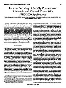
Figure 4: Internal structure of block T1 inside dashed box, and measurement transformations. 2 2 behavior of block T for a 4-state, rate R = 1/2 inner code and → σic Figure 5 shows the σout 1 i
an interference canceller for a fully loaded system with K = N = 15. We observe that increasing the 2 . The iterations numbers of iterations inside the block improves the output variance, in this case σic
rapidly approach the channel noise level, i.e., more or less complete cancellation is achieved. The VTR of block T1 depend on Eb /N0 . In our example we use Eb /N0 = 3dB, and the signal-to-noise ratio at the outer coded symbols is 3dB + 10 log(2/3) = 1.24dB, due to the rate loss through the inner decoder. 2 and σ 2 The variances σic out are a convenient way of quantifying the iteration behavior, and in during
the measurement of the VTRs, the input variable is generated with a Gaussian distribution. Figure 6 shows the workings of block T2 . It too can be iterated several times before the block T1 is activated, 2 constant. This block describes the behavior of the concatenated FEC system. holding the input σic
The number of iterations inside each block at each call is refered to as the iteration schedule (1)
(1)
(2)
(j)
(j)
S = (iT1 , iT2 , iT1 , · · · , iTl , · · ·), where iTl is the number of iterations in block Tl at its j-th call. The 2 → σ 2 behavior of situation is not quite as difficult to analyze as may appear. Figure 7 shows the σic out
block T2 for a 4-state, rate Ro = 2/3 outer code and the 4-state, rate Ri = 1/2 inner code, parametrized 9
1
0.9
: 1 iteration in T1 blk : 2 iterations in T1 blk : 3 iterations in T1 blk : 4 iterations in T1 blk : limit in T1 blk
0.8
Inner code: Ri = 1/2 recursive Canceller: K = N = 15, SNR = 1.24dB Interleaver depth = 15,000 Symbols
0.7
0.6
2 σic
0.5
0.4
0.3 channel noise level
0.2
0.1
0
0
0.1
0.2
0.3
0.4
0.5
0.6
0.7
0.8
0.9
1
2 σout
Figure 5: Variance transfer behavior of block T1 for different numbers of inner iterations. by the number of iterations peformed inside the block. Note that the input is on the vertical axis. It becomes evident that the output variance improves with the number of iterations, irrespective of the 2 2 is always the one for the most inner input variance, i.e., the smallest output variance σout for any σic
iterations, even though the effect of the iterations tends to saturate around 10. Combining Figures 7 and 5 into a single Figure 8 allows us to visualize the iterative behavior as the variances are exchanged between blocks T1 and T2 , where we have used the transfer curves for 15 internal iterations in block T2 , the serial FEC turbo decoder, and 4 internal iterations in block T1 . The plot shows an “open channel”, and the simulated iterations fit nicely into this channel, achieving convergence at an Eb /N0 = 1.8dB of this fully loaded system. The zig-zag line is an example of an actual simulation using this schedule. Decoding starts at the top right corner, and then bounces between the 2 = 0. lower and upper curves until it reaches σout
This is where our conclusions depart from current wisdom. In order to achieve the best performance, it is necessary to iterate the inner code and the interference canceller together. It is not sufficient to simply perform cancellation followed by iterated T2 block decoding. In order to illustrate that other iteration schedules are less beneficial, Figure 9 shows several examples: The leftmost figure shows the trajectory pair for using only single internal iterations in both blocks, and the variance transfer curves intersect causing the trajectory to get stuck. Likewise, the rightmost figure shows the use of 15 iterations in the FEC block T2 , but only a single iteration in block 10
(E)
λ (c~k(o)) Inner APP
(A)
-1 π (o) k
λ (c(o) k) Outer APP
(E)
λ (ck(o))
π (o) k (A)
λ (ck(i))
(A)
λ (c~k(o))
tanh()
LLR generation
variance calc
σout2
variance transform
σic2
(i)
ck
Figure 6: Internal structure of block T2 inside dashed box with its measurement transformations. T1 . This is the typically approach, and, again, the variance transfer curves intersect. The same holds true if only a single internal iteration is performed in the FEC block T2 , but multiple iterations in block T1 , as shown in the middle figure. It has been demonstrated by simulation that these alternate schedules do indeed break down at the same SNR of Eb /N0 = 1.8dB. Figure 10 shows the performance of this triple concatenated FEC/CDMA system and illustrates the occurance of the turbo cliff around Eb /N0 = 1.7dB for proper scheduling, which corresponds to a collapsing of the variance transfer channel. The capacity of the random CDMA channel at a rate R = R0 Ri = 1/3 can be calculated to be at Eb /N0 = 0.2dB, and hence our system performance is 1.5dB away from capacity. Note that the performance of the FEC system which inspired our design [3], experiences the turbo cliff around Eb /N0 = 0.8dB, wheres the capacity of the AWGN channel is at Eb /N0 = −0.65dB, also a distance of around 1.5dB to capacity. There, we conjecture that the ultimate closure to capacity can be achieved by the design the FEC system, using larger interleavers and finely adjusted component codes. This is the topic of current research, see [16].
5
Conclusions
We have presented a coding and decoding methodology for joint detection systems for CDMA which achieves near-Shannon limit performance by using serially concatenated simple FEC codes. The decoder is an iterative decoder for the triple serially concatenated system of FEC codes and CDMA channel which iterates soft information between four component systems, where the inner FEC decoder participates in both of two interlocked loops. The iteration schedule has been defined and a variance
11
1
0.9
: 1 iteration in T2 blk : 2 iterations in T2 blk : 3 iterations in T2 blk : 4 iterations in T2 blk : limit in T2 blk
0.8
0.7
0.6
2 σic
0.5
0.4
0.3
Inner code: Ri = 1/2 recursive Outer code: Ro = 2/3 recursive Interleaver depth = 15,000 Symbols
0.2
0.1
0
0
0.1
0.2
0.3
0.4
0.5
0.6
0.7
0.8
0.9
1
2 σout
Figure 7: Variance transfer behavior of block T2 parametrized with the number of inner iterations. transfer analysis has been presented and used to design the optimal iteration schedule for a decoder for an concatenated FEC system using 4-state inner and outer FEC codes on a fully loaded random CDMA system, and it has been demonstrated that this decoder achieves a performance close to the Shannon capacity of this channel.
12
1
0.9
: 4 iterations in T1 block, lower limit : 15 iterations in T2 block, upper limit
0.8
Canceller: K = N = 15, Eb /No = 1.8dB 0.7
0.6
2 σic
0.5
0.4
0.3
Inner code: Ri = 1/2 recursive Outer code: Ro = 2/3 recursive Outer Interleaver depth = 15,000 Symbols Inner Interleaver depth = 30,000 Symbols
0.2
0.1
0
0
0.1
0.2
0.3
0.4
0.5
0.6
0.7
0.8
0.9
1
2 σout
Figure 8: Variance transfer exchange between blocks T1 and T2 .
References [1] P. Alexander, A. Grant, and M. Reed, “Iterative detection in code-division multiple-access with error control coding,” European Trans. Telecommun., vol. 9, no. 5, pp. 419–426, Sept.–Oct. 1998. [2] P. D. Alexander, M. C. Reed, J. A. Asenstorfer and S. B. Schlegel, “Iterative multiuser interference reduction: Turbo CDMA”, IEEE Trans. Commun., vol 47, no 7, July 1999. [3] S. Benedetto, D. Divsalar, G. Montorsi and F. Pollara, “Serial concatenation of interleaved codes: Performance analysis, design, and iterative decoding”, IEEE Trans. Inform. Theory, vol. 44, pp. 909–926, May 1998. [4] S. Benedetto, D. Divsalar, G. Montorsi and F. Pollara, “Soft-output decoding algorithms in iterative decoding of turbo codes”, TDA Progress Rep., pp 63-87, Februaryk 1996. [5] S. Benedetto, D. Divsalar, G. Montorsi and F. Pollara, “ A soft-input soft-output maximum a posteriori(MAP) module to decode parallel and serial concatenatedcCodes”, TDA Progress Rep., pp 1-20, November 1996. [6] C. Berrou, A. Glavieux, and P. Thitimajshima, “Near Shannon limit error correcting coding and decoding: Turbo-codes,” Proc. 1993 IEEE Int. Conf. on Comm., Geneva, Switzerland, pp. 1064–1070, 1993. 13
1
1
1
0.9
0.9
0.9
0.8
0.8
0.8
0.7
0.7
0.7
0.6
0.6
0.6
0.5
0.5
0.5
0.4
0.4
0.4
0.3
0.3
0.3
0.2
0.2
0.2
0.1
0.1
0
0
0.1
0.2
0.3
0.4
0.5
0.6
0.7
0.8
0.9
1
One iteration each
0
0.1
0
0.1
0.2
0.3
0.4
0.5
0.6
0.7
0.8
0.9
1
0
0
One iteration FEC 4 Iterations CDMA
0.1
0.2
0.3
0.4
0.5
0.6
0.7
0.8
15 iterations FEC One iteration CDMA
Figure 9: Various unsuccessful iteration schedules. [7] C. Berrou and A. Glavieux, “Near Shannon limit error correcting coding and decoding: Turbocodes,” IEEE Trans. Commun., vol. COM-44, pp 1261–1271, October 1996. [8] T. R. Giallorenzi and S. G. Wilson, “Multiuser ML sequence estimator for convolutional code asynchronous DS-CDMA systems”, IEEE Trans. Commun., vol. COM-44, pp 997-1008, Aug. 1996. [9] T. R. Giallorenzi and S. G. Wilson, “Suboptimum multiuser receivers for convolutionally coded asynchronous DS-CDMA systems”, IEEE Trans. Commun., vol. COM-44, no 9, pp 1183-1196, Sept. 1996. [10] TIA/EIA/IS-95 Interim Standard, mobile station – base station compatibility standard for dualmode wideband spread spectrum cellular systems, Telecommunications Industry Association (TIA), Washington, DC, 1993. [11] M. Moher, “An iterative multiuser decoder for near-capacity communications”, IEEE Trans. Commun., vol. 47, pp. 870–880, July 1998. [12] K.R. Narayanan and G.L. Stuber, “ A Serial concatenation approach to iterative demodulation and decoding”, IEEE Trans. Commun., vol. 47, pp. 956–961, July 1999. [13] L.C. Perez, J. Seghers, and D.J. Costello, Jr., ”A distance spectrum interpretation of turbo codes,” IEEE Trans. Inform. Theory, vol. 42, no. 6, pp. 1698–1709, November 1996. [14] M.C. Reed, C.B. Schlegel, P.D. Alexander and J.A. Asenstorfer, “Iterative multiuser detection for CDMA with FEC: Near-single-user performance”, IEEE Trans. Commun., vol. 46, no. 12, pp. 1693–1699, December 1998. 14
0.9
1
1 K=15 N=15 inner code: 1/2 recursive code
Bit Error Rate
outer code: 2/3 recursive code
10
-1
SCCC interleaver length = 15,000 CDMA interleaver length = 30,000
10-2
10-3 1.4
1.5
1.6
1.7 Eb/N0
1.8
1.9
2
Figure 10: Near Shannon limit performance of the triple serially concatenated FEC/CDMA system. [15] C. Schlegel, Trellis Coding, IEEE Press, Piscataway, NJ, 1997. [16] C. Schlegel and S. Zhenning, “Multiuser detection research,” NSF Research Webpage, University of Utah: http://www2.elen.utah.edu/laboratories/commcenter/MUDetection.html [17] Telecommunications Industry Association (TIA) TR45.5.4. “The cdma2000 ITU-R RTT Candidate Submission”, available from http://www.itu.int/imt/, June 1998. [18] S. ten Brink, “Convergence behavior of iteratively decoded parallel concatenated codes,” IEEE Trans. Commun., submitted, March, 2000. [19] S. ten Brink, “A rate one-half code for approaching the Shannon limit by 0.1dB,” IEE Electronics Letters, vol. 36, no. 15, pp. 1293–1294, July 2000. [20] S. ten Brink, “Design of serially concatenated codes based on iterative decoding convergence,” Proceedings 2nd International Symposium on Turbo Codes & Related Topics, Brest, France, September 2000. [21] X. Wang and H.V. Poor, “Iterative (Turbo) soft interference cancellation and decoding for coded CDMA”, IEEE Trans. Commun., vol. 47, no. 7, July 1999.
15