Chen Yuen Teoh
JUNCTION EXTRACTION FROM HIGH RESOLUTION IMAGES BY COMPOSITE LEARNING Chen Yuen TEOH, Arcot SOWMYA Department of Artificial Intelligence School of Computer Science and Engineering University of New South Wales Sydney, Australia
[email protected] KEY WORDS: Road Extraction, Remote Sensing, Pattern Recognition. ABSTRACT This paper aims to present the junction recognition level of RECoiL, a system for Road Extraction from High Resolution Images by Composite Learning. By modelling junctions as specific junction types and learning different rules for each junction type, junction extraction is achieved. A clustering technique also has been applied to the same task using the same features identified during supervised learning, and the results are compared. 1 INTRODUCTION Roads are a major man-made surface feature and communication infrastructure among people. Maps are an abstraction of the real world, and creation and revision of maps are important processes for governments and businesses. Even though modern cartographers utilize Geographical Information Systems (GIS) databases for map storing and manipulation purposes, map creation is still dominated by manual techniques. Therefore semi or full automatic road recognition and extraction from remote sensing images will certainly aid faster and more accurate map maintenance. Machine learning is an Artificial Intelligence (AI) approach that could achieve automatic road recognition. In previous research (17), we have described Road Extraction from High Resolution Images by Composite Learning, RECoiL, which is a semi-automatic, multi-level, adaptive and trainable road recognition system based on supervised learning and K-means clustering (6) technique. RECoiL produces promising output by reducing the data set, while also generating comprehensible rules for recognition and avoiding the arduous labour of example selection tasks at lower levels. In addition using clustering techniques, we also manage to achieve similar results to supervised learning techniques currently maintains for the same task. In this paper we discuss the junction recognition level of RECoiL. Our approach to junction recognition is to divide junctions into different types and tackling them one by one. By applying a supervised learning technique to different junction types, we manage to extract junction based edges from an edge image. The current results of extraction are still preliminary and many more examples of a particular junction type are required to train the system. The most common approach for extracting roads is by detecting or tracking elongated lines in low resolution images, while profile matching or detection of parallel lines is used for high resolution images (2). Others combine these methods with prior knowledge to achieve semi or automatic road extraction (11, 19). The knowledge based approach is another common technique for road extraction, which can be divided into two categories. In the first category, an expert system and expert knowledge are used to formulate rules to guide the extraction system (7, 9). However these systems have limited application as they require extensive prior knowledge and are source dependent. The second category is to make use of external knowledge such as GIS data and maps (2, 4). However, availability of such prior data is not always guaranteed. Roads may also be extracted from multi-source images such as multi-sensor, multi-temporal, multi-scale and multiresolution images (3, 10, 18). However this approach suffers from image registration problems and paucity of multiple images of the same location. A grouping approach is yet another alternative (1), where the extraction system groups edges into road parts and segments, finally linking with junctions to form road networks. A model based extraction system was introduced (16), that groups roads using different knowledge of roads. Contextual information of a scene was used (13), where different techniques for road extraction are applied to different contexts of images. Machine learning techniques for remote sensing applications remain rare. Huang et al. (8) proposed a supervised learning based system which generates rules for scene analysis and Dillon et al. (5) proposed an Image interpretation and Scene understanding system (CITE) which uses incremental, relational learning to label a scene. 882
International Archives of Photogrammetry and Remote Sensing. Vol. XXXIII, Part B3. Amsterdam 2000.
Chen Yuen Teoh
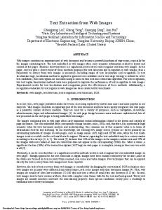
2 RECOIL FRAMEWORK RECoiL is developed based on Road Recognition from Aerial Images using Inductive Learning, RAIL, by Sowmya and Singh (14, 15). RAIL uses supervised multi-level learning to derive rules based on arduous example selection, while RECoiL bypasses this problem by implementing a clustering module, which is useful at levels where comprehensible recognition rules are not required. The road detection process for RECoiL is conceptualised into four levels: road segment detection, linking road segments, junction detection and linking roads to junctions. At each separate level, different features are targeted. Examples are pixel-based ones at lower levels and, relations between pairs of edges at higher levels. The recognition rules learned at one level are applied at that level, and the resulting image becomes the input to the next level, and eventually road-liked objects are recognised from the images. The structured diagram of RAIL is shown in figure 1. C4.5 is the learning program used for learning rules. Pre-processing
Original Image
Vista Canny Operator
Gradient Image
Link
Edge Image
Edges
Curve Splitting
Image with Straight Edges
Clustering Level 1 GUI Example Selection
Apply learned rules Generate Road Segment
Level 1 Clustering Level 2
Clustering Level 3 GUI Example Selection
GUI Example Selection
Apply learned rules Generate Linked Road Segment
Apply learned rules Generate Junction
Level 2
Level 3
Fusing output of level 2 and level 3
Road recognised and extracted
Figure 1: Proposed System 3 REVIEW OF RECOIL The operations of RECoiL can generally divided into three steps for each level of RECoiL (17). For supervised learning, the three steps are examples selection using custom built GUI system, rules learning using C4.5 and applying rules to input image and generating output image. Using the clustering approach, the three steps are generation of cluster data, applying K-means algorithm to cluster the generated data and finally display/select/saving the required cluster. As mentioned before, RECoiL is based on a hierarchical multilevel framework, which ranges from level 1 to level 4. Prior to level 1 is a preprocessing level. At this level, the primary aim is to extract an edge image from the remote sensing raster image. There are three separate steps involved, which are edge tracking, edge linking and curve splitting. Level 0 is an abstract and optional level for RECoiL. It resembles the clustering module at level 1, and the output of level 0 will be used as input for level 1. The targeted features at level 0 are similar to the features used in level 1 described in figure 2 (a). Level 1 aims to extract road pairs which are in the form of pairs of edges. The targeted features at this level are described in figure 2 (a). Another special attribute is also used for extracting road pairs, which is spatial overlapping that is required for edges to form a road pair. Meanwhile, level 2 aims to link the pairs of road segments extracted at the previous level to form linked road segments, without any connectivity with junctions based edges. Again, targeted features at this level are described in figure 2 (b). Level 3 of RECoiL is mainly focused on junction based edges extraction and will be described in detail in section 4. As for level 4 of RECoiL, it is still under development and will focus on fusion of the outputs from level 2 and level 3 of RECoiL to form the road-liked edge image. Due to the implementation of hierarchical multilevel framework, RECoiL allows combination of different modules at different levels. Even though the possible combinations are plentiful, only a few important and useful combinations are described in Table 1. International Archives of Photogrammetry and Remote Sensing. Vol. XXXIII, Part B3. Amsterdam 2000.
883
Chen Yuen Teoh
Attributes
Pictorial Illustration
Separation between a pair of edges
Property of Road Model Addressed Deals with basic road properties that a road segment must have a minimum and a maximum of width
x
Attributes
Pictorial Illustration
Minimum Seperation
Difference in Spatial direction
Deals with basic road property that 2 linkng road segments should have minimal separation, normally caused by noise.
x
Seperation = x
y The road property that a road segment must be running in parallel direction or near parallel direction
dir x
Property of Road Model Addressed
Minimum Seperation = max(x, y)
dir y
Gap Difference
Difference = (dir x - dir y)
Difference in Gradient direction
gradient dir x
x
The road property that a road segment has opposite gradient directions
Deal with basic road properties that 2 linking road segments should not have big difference in width.
y Difference = max(x, y)
gradient dir x Difference = (gradient dir x gradient dir y)
Average enclosed intensity
Spatial Direction Difference
11111111 00000000 00000000 11111111
dir b
Image property for road model, by having smooth higher intensity from border to border, within a road segment
Difference in intensity with the surrounding
Width Difference x
111111111 000000000 000000000 111111111 0000000 1111111 0000000 1111111 000000000 111111111 0000000 1111111 0000000 1111111 111111111 000000000 111111111 000000000
Addressing the fact that road surfaces have higher colour intensity than other surface material
dir c dir d
Deals with basic road property that 2 linking road segments should have similar spatial direction, i.e.: changes is angle or direction should be minimal.
Difference = max((dir a-dir c),(dir b-dir d))
Intensity Average Intensity = avg(Intensity of all pixels within the enclosed boundary)
dir a
y
Deals with basic road properties that 2 linking road segments should not have wide changes in width ..
Difference = (x - y) Intensity Difference
1111 0000 0000 0000 1111 1111 0000 1111 intensity x
Intensity y
intensity y
Intensity x Difference = (intensity x intensity y)
Deals with image property of road model that linking two road segments, the intensity of these two candidates should have similar intensity, i.e.: minimal intensity difference.
Intensity = (Intensity x Intensity y)
(a) Level 1
(b) Level 2
Figure 2: Features targeted at Different Levels
Exp. # 1 2 3
Combination L0/L1/L2/L3 Preprocessed CL/No/No/No CL/ML/No/No CL/ML/ML/No
Level 0 NE 6481 2644 2644 2644
L1 NE
L2 NE
252 252
86
Figure # 3 (b) 2 (a) 2 (b) 2 (c)
Table 1: Result SummaryML: Machine Learning; CL: Clustering; Li: Level i of the System; NE: Number of Edges
884
International Archives of Photogrammetry and Remote Sensing. Vol. XXXIII, Part B3. Amsterdam 2000.
Chen Yuen Teoh
Figure 3 are the outputs at level 0, 1 and 2 respectively, where the latter two are outputs generated using supervised learning technique.
(a) Level 0
(b) Level 1
(c) Level 2
Figure 3: Output at Different Levels 4 JUNCTION RECOGNITION LEVEL The aim of this level of extraction is to extract junction based edges, which can then be fused with the result of level 2 to form a complete map-like road network. At this level the junction models have been subdivided into different types for recognition purpose, which are described in figure 4. L Junction Default number of Pairs: 2
Y Junction Default number of Pairs: 3
T Junction Default number of Pairs: 3
X Junction Default number of Pairs: 4
Star Junction Default number of Pairs: 5
Figure 4: Different Junction Types The identified attributes at this level are described in Table 2, which are used for both learning techniques. One major feature of some attributes at this level is the use of qualitative descriptions of angle as opposed to only the quantitative description used in previous levels. This is important since the angle between two connecting road pairs will not be a fixed number, eg. 0 , but instead they may be within a range of possible values. Besides, qualitative descriptions will enhance comprehensibility of learned rules. Finally, each junction type will have distinct attribute values.
90
Using the learning program, C4.5, the rules learned from 28 training examples, for a T-junction model is shown below, with an error rate of when tested on 28 new examples. The high error rate shows that the examples provided for learning are not sufficient. For learning purpose, examples provided should be in magnitude of hundreds.
37%
International Archives of Photogrammetry and Remote Sensing. Vol. XXXIII, Part B3. Amsterdam 2000.
885
Chen Yuen Teoh
Attribute Number of Pairs Intensity Difference Width Difference Minimum/Maximum Gap Minimum/Maximum Angle’s Type List of Angles’ Type
Property of Junction Model Addressed There might be different pairs of road segments that join to form a junction Neighbouring road segments should have similar intensity value. Neighbouring road segments should have similar width, or minimum width difference. Junction should have a minimum/maximum gap between the closest two edges from the two pairs. Junction should have different angles, and minimum/ maximum angle for a list of angles measured. There exist different types of angle between two connecting road segments. Table 2: Level 3 Attributes List
Rule 1: Rule 3:
Rule 4:
Rule 2:
Max Gap class Junction [79.4%] Intensity Difference > 17.1 Min Gap class Junction [63.0%] Min Gap > 2 Max Gap > 101.5 -> class Not_Junction [91.7%] Intensity Difference 101.5 -> class Not_Junction [88.2%]
Default class: Not_Junction Evaluation on training data (28 items): Rule Size Error Used Wrong Advantage ---- ---- ----- ---- ------------1 1 20.6% 6 0 (0.0%) 5 (5|0) Junction 3 2 37.0% 2 0 (0.0%) 2 (2|0) Junction 4 2 8.3% 16 0 (0.0%) 0 (0|0) Not_Junction 2 2 11.8% 4 0 (0.0%) 0 (0|0) Not_Junction Tested 28, errors 0 (0.0%)