Kalman Filter Based Microgrid State Estimation and Control Using the IoT with 5G Networks Md Masud Rana, Li Li and Steven Su Faculty of Engineering and Information Technology University of Technology, Sydney, Broadway, NSW 2007, Australia Email:
[email protected] Abstract—Given the significant concerns regarding carbon emissions from fossil fuels, global warming and energy crisis, the renewable distributed energy resources (DERs) are going to be integrated in smart grids, which will make the energy supply more reliable and decrease the cost and transmission losses. Unfortunately, one of the key technical challenges in power system planning, control and operation with DERs is the voltage regulation at the distribution level. This problem stimulates the deployment of smart sensors and actuators in smart grids so that the voltage regulation can be controlled at an accepted level. The observation from the multiple DERs information is transmitted to a control center via the internet of things (IoT) based fifth generation (5G) communication network. In other words, the proposed communication infrastructure provides an opportunity to address the voltage regulation challenge by offering the two-way communication links for microgrid state information collection, estimation and control. Based on this innovative communication infrastructure, we propose a least square based Kalman filter for state estimation and a feedback control method for voltage regulation of this intermittent and weather-dependent renewable power generation. Specifically, we propose to optimize the performance index by using semidefinite programming techniques in the context of smart grid applications. At the end, the efficacy of the developed approaches is demonstrated using the linear physical model of a microgrid incorporating DERs. Index Terms—Communication network, distributed energy resource, internet of things, Kalman filter, smart grid, state estimation.
I. I NTRODUCTION Global warming in one of the biggest concerns all over the world. The main reason behind is the increasing greenhouse gas emissions from burning fossil fuels and vehicles [1]. In order to mitigate this issue, the renewable distributed energy resource (DER) is considered as one of the potential electricity generation units [1], [2]. However, significant technical challenges arise in the planning, operation and control of DERs, due to the randomness and weather-dependence in the power generation [3]. Consequently, an unacceptable voltage level may frequently occur at the point common coupling (PCC). Motivated by this, voltage regulators should be installed at planned positions of the distributed feeders [2], [4]. Interestingly, the bidirectional smart grid communication between the microgrid and the control center can be leveraged to facilitate voltage regulation problems [5], [6]. The main ideas of such intelligent energy management systems are parallel to those of the internet of things (IoT) which can exploit reasonable security and privacy of DERs information,
seamless interoperability and far-reaching connectivity [7], [8]. The IoT can integrate heterogeneous devices and technologies to create a seamless global communication platform [9]. It consists of intelligent sensing devices such as smart sensors, intelligent systems and smart processor to make a digital green world [10], [11]. To achieve the aims, the fifth generation (5G) network will be the potential infrastructure assisting the visions of the IoT. The 5G networks will entail smart nodes with heterogeneous characteristics and capacities, which will result in a multi-tier architecture. This technology can effectively enable new facilities, security and high data rate services to everyone and every device [13], [14]. Based on the information and communication technology infrastructure, the smart grid can spread the intelligence of the distribution system from the central unit to the long-distance remote areas, thus enabling accurate state estimation (SE) and wide-area real-time monitoring of intermittent renewable energy sources [15] [16]. The KF based SE is widely used in the literature that provides a recursive update of the state estimate during the system operation [7]. Recently, a BP based static state estimator for the IEEE 4-bus distributed system is proposed in [17]. However, the system states usually change over time continuously. In fact, a BP algorithm for unregulated dynamic SE for a simple example of microgrid is proposed in [18]. Unfortunately, the computational complexity of the BP method is very high, even though the performance is almost the same at a high signal-to-noise ratio. Furthermore, the microgrid is to integrate the multiple DERs into the main grid, which needs to be controlled properly as it is distributed in remote areas. An alternative approach is thus required to monitor and control such a system integrating multiple DERs using a flexible sensing network. Motivated by the aforementioned work, this paper proposes an approach for microgrid state estimation and control using the IoT with 5G networks. First of all, a microgrid incorporating multiple DERs is modelled as a discrete linear system considering the uncertainty. Flexible and cost-effective smart sensors are deployed to get the DER state information. After that, the observation from the multiple DERs information is transmitted to a control center via the IoT based 5G communication network. Based on this innovative communication infrastructure, we propose a least square based KF algorithm for state estimation and a feedback control strategy for voltage regulation of this intermittent and weather-dependence
renewable power generation. Specifically, in order to regulate the voltage deviation, this study proposes an optimal control method based on semidefinite programming techniques. This proposed feedback control scheme acts as a precursors in term of network stability and the operation of DERs Consequently, a new sensing, state estimation and control strategy for the microgrid incorporating DERs is derived with the help of the IoT and 5G networks. The effectiveness of the developed approaches is verified by numerical simulations using a microgrid incorporating DERs. Notation: Bold face lower and upper case letters are used to represent vectors and matrices, respectively; superscripts x∗ and xT denote the conjugate and transpose of x, respectively; I is the identity matrix. II. M ICROGRID MODEL To apply a strategy to keep the PCC voltage at an acceptable level, this paper considers a microgrid model of interconnected DERs as shown in Fig. 1 [2]. It is assumed that three DERs are
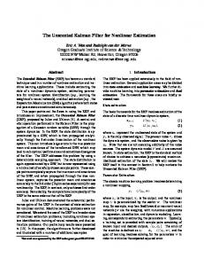
Snapshot of the system Substation and sensors
DERs
Base station Smart city
Fig. 2.
State estimator software
Smart house
The proposed simplified 5G communication systems.
0.6 0.1 0.2 Bd = 0.1 0.7 0.15 . 0.2 0.15 0.8
(3)
In order to sense the DER states, the communication network architecture describes in the next subsection. III. P ROPOSED COMMUNICATION SYSTEMS
Vs1
Vp1
R1
L1
Input
DER1
R2 Vp2
Vp3
Vs2
Input
Vs3 R
The communication network brings about new perspectives to energy management systems and covers a diverse range of communication technologies including sensing, networking, information processing and intelligent control technologies [15]. To achieve the goal, the utility company deploys a lot of sensors in the electricity network for monitoring system states [2], [4]. The sensors can send their measurements to the control center via the proposed communication system. Mathematically, the observations from the DER states information are obtained by a set of sensors as follows:
Rs Grid
L2
DER2
R3
L3
Input
DER3
Ground
y(k) = Cx(k) + w(k),
(4)
modelled as voltage sources whose input voltages are denoted by vp = (vp1 vp2 vp3 )T , where vpi is the i-th DER input voltage. Three DERs are connected to the main grid and three voltage monitoring sensors are installed in the system with the sensing voltages denoted by vs = (vs1 vs2 vs3 )T . In order to maintain the proper operation of DERs, these voltages need to be kept at a desired level. Generally, the dynamics of the physical system is given by:
where y(k) is the observation information, C is the sensing matrix and w(k) is the zero mean observation noise whose covariance matrix is Rw . The observation information by the WSN powered by 5G technologies is transmitted to the nearby base station. After that, the uniform quantizer of this base station maps each observation signal to a sequence of bits. The bit sequence b(k) is passed through the binary phase shift keying (BPSK), and the modulated signal s(k) is obtained. The modulated signal goes through the internet with some noise. To illustrate, Fig. 2 shows the proposed communication systems in the context of microgrid state estimation. At the end, the received signal is given by:
x(k + 1) = Ad x(k) + Bd u(k) + n(k),
r(k) = s(k) + e(k),
Fig. 1.
Simplified grid connected microgrid with multiple DERs [2].
(1)
where vref is the reference voltage, x(k) = vs − vref is the voltage deviation, u(k) = vp − vpref is the control input deviation, vpref is the reference control effort, n(k) is the zero mean process noise whose covariance matrix is Qn , and the state matrix Ad and input matrix Bd are given by: 1.03 0 0 1.02 0 , Ad = 0 (2) 0 0 1.05
(5)
where e(k) is the additive white Gaussian noise (AWGN). Followed by demodulation and dequantization, the received signal is then used for state estimation of the dynamic system. IV. P ROPOSED CENTRALIZED DER S STATE ESTIMATION The energy management system computes the following KF steps as follows [19]: ˆx− (k) = Ad ˆx(k − 1) + Bd u ˆ(k − 1),
(6)
where ˆx(k − 1) is the estimate states of the last step. The predicted estimate covariance matrix is given by: P− (k) = Ad P(k − 1)ATd + Qn (k − 1),
(7)
where P(k − 1) is the estimate covariance matrix of the last step. The measurement residual d(k) is given by: d(k) = yrd (k) − Cˆ x− (k),
(8)
where B1 = I, Qz and Rz are the positive definite state and control weighting matrices, respectively. In order to find the optimal feedback gain, we search for a feedback gain matrix F that solves the H2 norm minimization problem as follows: minimise
trace[BT1 PB1 ]
subject to
P − (Ad − Bd F) P(Ad − Bd F) < Qz + F Rz F, (18)
where yrd (k) is the dequantized and demodulated output bit sequences. The Kalman gain is given by: K(k) = P− (k)CT [CP− (k)CT + Rw (k)]−1 .
(9)
The updated state estimation is given by: ˆx(k) = ˆ x− (k) + K(k)d(k).
(10)
The updated estimate covariance matrix P(k) for the KF is given by: P(k) = P− (k) − K(k)CP− (k).
ˆx(0) = (CT C)† CT yrd (0),
(12)
where (·)† denotes the pseudo inverse. After estimating the system state, the proposed control method is applied for regulating the DER state deviation as shown in the following section. V. P ROPOSED OPTIMAL FEEDBACK CONTROL METHOD We first assume that the state information is available. In order to regulate the DER state, consider the following performance output signal: [ 1/2 ] [ ] 0 Qz z(k) = x(k) + u(k), (13) R1/2 0 z where Qz and Rz are strict positive definite matrices. Define the following state feedback control law: u(k) = −Fx(k),
(14)
by minimizing the H2 norm of the closed-loop system [22], [23]. Here, F is the state feedback gain matrix. The simulation result in the next section shows that the proposed estimation technique is able to estimate the system state properly. Therefore, according to the separation principle [24, p. 427], we can implement the control law u(k) = −Fˆ x(k) [25]. For the state feedback (14), the closed-loop system is described by [23]: x(k + 1) = (Ad − Bd F)x(k) + B1 n(k), [ ] Q1/2 z z(k) = x(k), −R1/2 z F
P > 0.
(15) (16)
(19)
In order to solve the above problem by using semidefinite ˜ = P−1 . Then equations (17)-(19) can programming, define P be transformed into the following form: minimise subject to
˜ trace[BT1 P
−1
B1 ]
˜ (Ad − Bd F)T P
(20)
−1
˜ (Ad − Bd F) − P
−1
T
F Rz F < 0, ˜ > 0. P
(11)
From the Eq. (6), it can be seen that one needs to specify the initial state value ˆ x(k = 0) to run the KF algorithm. There are no general procedures to estimate the initial state value [20]. In practice, researchers often set ˆ x(0) = 0 as an estimate of the initial state value [20], [21]. As a result, the initial estimation is usually far away from the true DER initial states. To obtain a good initial estimation, this paper adopts a least square estimation method [21]. For instance, one can obtain the initial estimation ˆ x(0) as follows:
(17) T
T
+ Qz + (21) (22)
˜ equations (20)-(22) After the congruence transformation by P, can be transformed into the following form: minimise
˜ trace[BT1 P
−1
B1 ]
˜ d − Bd F)T P ˜ subject to P(A ˜ T R z FP ˜ < 0, PF
(23)
−1
˜−P ˜ + PQ ˜ z P+ ˜ (Ad − Bd F)P (24)
˜ > 0. P
(25)
It can be observed that the Eq. (24) is nonlinear because it ˜ and F. This prevents involves the multiplication of variables P a straightforward application of linear matrix inequality (LMI). ˜ and Fortunately, one can introduce a new variable X = FP rewrite the Eq. (24) as follows: ˜ − Bd X)T P ˜ −1 (Ad P ˜ − Bd X) − P ˜ + PQ ˜ zP ˜ + XT Rz X < 0. (Ad P (26) Now according to the Schur’s complement Eq. (26) can be transformed into the following form: ˜ ˜ ˜ Td − XT BTd −P P XT PA ˜ P −Q−1 0 0 z < 0. −1 X 0 − Rz 0 ˜ ˜ Ad P − Bd X 0 0 −P (27) ˜ −1 B1 in (23) is replaced by S, the above If the term BT1 P optimization problem can be formulated as follows: minimise subject to
trace[S] −1
B1 − S < 0, ˜ > 0. Hold (27), P
˜ BT1 P
(28) (29) (30)
According to the Schur’s complement, one can rewrite (29) as follows: [ ] −S BT1 (31) ˜ < 0. B1 −P
In order to control the DER states, one can finally formulate the proposed optimization problem as follows: trace[S]
(32)
subject to
˜ > 0. Hold (27), Hold (31), P
(33)
One can use the standard YALMIP toolbox to solve the proposed optimization problem [26]. At the end, the feedback gain matrix is computed as: ˜ −1 . F = XP
(34)
State deviation, per unit
minimise
6
Fig. 4.
Parameters Modulation Quantization Rz
Values BPSK 16 bits eye(3)
Parameters Qn Rw Qz
Values 0.0005*I(3) 0.05*I(3) diag(10 1 20)
3 2
10
20
30 40 Time slot k
50
60
∆v2 comparison between the true and estimated state.
40
State deviation, per unit
TABLE I PARAMETERS FOR SIMULATIONS .
4
0 0
The performance of the aforementioned algorithms are explored by performing extensive numerical simulations. All simulation parameters are summarized in Table I. This simulation is performed using MATLAB and YALMIP. T HE SYSTEM
True state ∆v2 Proposed method Existing method
1
The simulation results of the proposed KF based DER state estimation and control method are demonstrated in the next section. VI. P ERFORMANCE A NALYSIS
5
35
True state ∆v3
30
Proposed method Existing method
25 20 15 10 5 0 0
10
20
5
State deviation, per unit
True state ∆v1 4
3
50
60
∆v3 comparison between the true and estimated state.
Therefore, it is necessary to apply a proper control method, so that the voltage deviations are driven to zero. After applying the proposed control method, it can be seen from Table II that the eigen values of the closed-loop state matrix are within the unity circle. It can also be seen in Fig.6 that the proposed
2
1
0 0
Fig. 3.
Fig. 5.
Proposed method Existing method
30 40 Time slot k
10
20
30 40 Time slot k
50
60
∆v1 comparison between the true and estimated state.
Considering the above parameters, the simulation results are presented in Figs. 3-5. From the results, it is observed that the proposed approach is able to estimate the system state properly. This accurate estimation is obtained using the proposed estimation method. Note that the small fluctuations come from the statistical information such as process, observation and channel noises. Unfortunately, it is noticed that the true voltage deviations increase dramatically, which is very dangerous in terms of network stability and the operation of DERs. Furthermore, the eigen values of the original state matrix are greater than one.
TABLE II T HE EIGEN VALUES COMPARISON . Original system 1.03 1.02 1.05
Proposed control method 0.1247 0.4509 0.5471
controller is able to keep voltage deviations to zero by the time k=10, which acts as a precursor in terms of network stability and proper operation of DERs. Besides, the corresponding control input of each DER is shown in Fig. 7, which implies that it requires a small amount of the control input voltage. VII. C ONCLUSIONS This paper addresses the voltage regulation issue from the communication perspective. To do so, wireless sensor network
2.5 2 State deviation, per unit
∆v1 ∆v2
1.5
∆v
3
1 0.5 0 −0.5
5
10 Time slot k
Fig. 6.
15
20
Voltage control.
Control effort, per unit
0.5 0 −0.5
∆u1
−1
∆u3
∆u
2
−1.5
5 Fig. 7.
10 15 Time slot k
20
Input voltage variations.
components such as sensors and actuators have been applied into the microgrid to coordinate DER states regulation. In order to transmit the sensing information to the observer, the proposed innovative communication systems have been utilized. Based on this infrastructure, this paper also proposes a least square based KF algorithm for centralized DER state estimation. Finally, in order to regulate the voltage deviation, this study proposes an optimal control strategy based on semidefinite programming. As a result, a new sensing, state estimation and control scheme for microgrids incorporating DERs is derived using the IoT with 5G networks. At the end, the effectiveness of the developed approaches is verified by numerical simulations. R EFERENCES [1] X. Zhang, W. Pei, W. Deng, Y. Du, Z. Qi, and Z. Dong, “Emerging smart grid technology for mitigating global warming,” International Journal of Energy Research, 2015. [2] R. Mao and H. Li, “Nobody but you: Sensor selection for voltage regulation in smart grid,” arXiv preprint arXiv:1103.5441, 2011. [3] H. Liang and W. Zhuang, “Stochastic modeling and optimization in a microgrid: A survey,” Energies, vol. 7, no. 4, pp. 2027–2050, 2014. [4] X. Wang and Q. Liang, “Stabilizing the power supply in microgrid using sensor selection,” in of the Global Communications Conference. IEEE, 2012, pp. 3513–3518.
[5] H. Liang, A. Abdrabou, and W. Zhuang, “Stochastic information management for voltage regulation in smart distribution systems,” in Proc. of the INFOCOM. IEEE, 2014, pp. 2652–2660. [6] M. M. Rana and L. Li, “An overview of distributed microgrid state estimation and control for smart grids,” Sensors, vol. 15, no. 2, pp. 4302–4325, 2015. [7] ——, “Microgrid state estimation and control for smart grid and the internet of things communication network,” Electronics Letters, vol. 51, no. 2, p. 149151, 2015. [8] J. Guo, H. Zhang, Y. Sun, and R. Bie, “Square-root unscented Kalman filtering-based localization and tracking in the internet of things,” Personal and ubiquitous computing, vol. 18, no. 4, pp. 987–996, 2014. [9] M. Yun and B. Yuxin, “Research on the architecture and key technology of internet of things (iot) applied on smart grid,” in Advances in Energy Engineering, 2010 International Conference on. IEEE, 2010, pp. 69– 72. [10] J. Huang, Y. Meng, X. Gong, Y. Liu, and Q. Duan, “A novel deployment scheme for green internet of things,” Internet of Things Journal, vol. 1, no. 2, pp. 196–205, 2014. [11] I. Bojanova, G. Hurlburt, and J. Voas, “Imagineering an internet of anything,” Computer, no. 6, pp. 72–77, 2014. [12] S. P. Nelson, “Bringing the iot home,” Freescale Semiconductor Inc, pp. 1–20, 2014. [13] D. Soldani and A. Manzalini, “Horizon 2020 and beyond: On the 5G operating system for a true digital society,” IEEE Vehicular Technology Magazine, vol. 10, no. 1, pp. 32–42, 2015. [14] S. Talwar, D. Choudhury, K. Dimou, E. Aryafar, B. Bangerter, and K. Stewart, “Enabling technologies and architectures for 5G wireless,” in Microwave Symposium. IEEE, 2014, pp. 1–4. [15] N. Kayastha, D. Niyato, E. Hossain, and Z. Han, “Smart grid sensor data collection, communication, and networking: A tutorial,” Wireless Communications and Mobile Computing, 2012. [16] A. P. S. Meliopoulos, G. J. Cokkinides, R. Huang, E. Farantatos, S. Choi, Y. Lee, and X. Yu, “Smart grid technologies for autonomous operation and control,” IEEE Transactions on Smart Grid, vol. 2, no. 1, pp. 1–10, 2011. [17] Y. Hu, A. Kuh, and A. Kavcic, “A belief propagation based power distribution system state estimator,” IEEE Computational Intelligence Magazine, vol. 6, no. 3, pp. 36–46, 2011. [18] S. Gong, H. Li, L. Lai, and R. C. Qiu, “Decoding the nature encoded messages for distributed energy generation control in microgrid,” in Proc. of the International Conference on Communications, 2011, pp. 1–5. [19] D. Simon, Optimal state estimation: Kalman, H infinity, and nonlinear approaches. New Jersey: John Wiley and Sons, 2006. [20] V. Radisavljevic-Gajic, “Linear observers design and implementation,” in Proc. of the Zone 1 Conference of th American Society for Engineering Education. IEEE, 2014, pp. 1–6. [21] C. Johnson, “Optimal initial conditions for full-order observers,” International Journal of Control, vol. 48, no. 3, pp. 857–864, 1988. [22] K. Zhou, J. C. Doyle, K. Glover et al., Robust and optimal control. Prentice hall New Jersey, 1996, vol. 40. [23] M. Fardad and M. R. Jovanovic, “On the design of optimal structured and sparse feedback gains via sequential convex programming,” in Proc. of the American Control Conference. IEEE, 2014, pp. 2426–2431. [24] M. Gopal, Digital Control and State Variable methods Conventional and Neural-Fuzzy Control System. New Delhi, India: McGraw-Hill, 2003. [25] A. K. Singh, R. Singh, and B. C. Pal, “Stability analysis of networked control in smart grids,” IEEE Transactions on Smart Grid, vol. 6, no. 1, pp. 381–390, 2015. [26] J. Lofberg, “YALMIP: A toolbox for modeling and optimization in matlab,” in Proc. of the International Symposium on Computer Aided Control Systems Design, 2004, pp. 284–289.