International Journal of M echanics and Applications 2012, 2(5): 49-60 DOI: 10.5923/j.mechanics.20120205.01
Knowledge Based Simulation Driven Design for Crash Applications J. Badin1,2,* , D. Chamoret1 , S. Roth1 , J. R. Imbert2 , S. Gomes1 1 IRTES-M 3M , University of Technology, UTBM , 90010, Belfort Cedex, France DPS - Digital Product Simulation, Espace Claude M onet, 2-4 rue Hans List, 78290, Croissy- sur- Seine, France
2
Abstract This paper focuses on industrial design and crash simulation. Indeed, crash simulation has progressed considerably to become a key area in product design, especially in auto motive industry. The main object ive of this paper is to show the role of the numerical simu lation on the design process and to explain its integration in this process. Actually, we can now talk about a strong connection between the simulation and the design process. It allows significant gains, however it highlights the problem of co llaboration around knowledge in the design process. Indeed, each expert model is driven by specific data which are shared by several users and used at the same time in a concurrent engineering context. Thus in this paper, we propose at first an assess of differents kind of crash simulation integration on design process and their benefits/limits. Then we propose an approach referred to as KCM – Knowledge Configuration Management, based on management of fine granularity knowledge in configuration. This approach is likely to imp rove collaboration between project participants, improving capitalization, traceability, reuse and consistency of the knowledge used simultaneously on several activities in parallel within the design process. Finally, the purpose of our paper is to find new ways to further optimize the simu lation/Design integration through an approach of knowledge management which is a new challenge today in industry.
Keywords
Crash, Simu lation Design Process, Concurrent Engineering, Knowledge Management
1. Introduction Although the design process has evolved, the numerical simu lation has also progressed considerably to become a key area in product design. Init ially used at the end of the design process as validation or presentation of activities, simu lation is currently used in the overall design process and especially in the upstream phase (trade-off, pre-design) using CAD-CA E integration and parametric models to drive the design and identify the better concepts of product’s architecture earlier. Thus, nowadays, it seems as necessary to use numerical simu lation, especially the fin ite element simu lation to lead the way to innovation [1-2]. In the early d es ig n p has es , n u merical s imu lat io n allo ws fo r t he man agement o f a better d es ign and qu icker. Th is is particularly true in the area of mechanical systems mo re s pecifically in t h e au t o mo t iv e in d us t ry wh ere t h e development speed has to be increased. That is the reason wh y th e crash s imu lat io n techn iques are gain ing an increas ing ro le in the product dev elop ment instead of time-consuming validation testing.These evolut ions have * Corresponding author:
[email protected] (J. Badin) Published online at http://journal.sapub.org/mechanics Copyright © 2012 Scientific & Academic Publishing. All Rights Reserved
led to a strong connexion between the design process and the numerical simu lation and today we talk about “simu lation driven design method” (Figure 1).. In this way it helps to streamline the design process, and to better take into account the constraints from the various expert domains in the product design and a better control. Indeed, the idea is to minimize physical prototypes which are very expensive to make and use the simulat ion even for the certification. Thus one of classical objective in automotive industry for future is to produce a car with just one prototype good at the first time.
Figure 1. Using numerical simulation overall the design process (Simulation Driven Design)
We will present in this paper the fundamental ro le of numerical simu lation of crash in the design process. It allo ws significant gains, however it high lights the problem
50
J. Badin et al.: Knowledge Based Simulation Driven Design for Crash Applications
of collaboration around knowledge in the design process [3]. This paper is organised as follows: section 2 presents the place of numerical simu lation in the design process. In section 3, Several Industrial Methods for CAD-CEA integration are presented. In section 4, the necessity to improve expert models interoperability is evoked which leads to the management of knowledge embedded in CAD and CA E modelling and simu lation software tools. Sections 5 and 6 illustrate the use these new tools in the specific context of crash. Sect ion 7 concludes the research.
2. Numerical Simulation in the Design Process
These models are termed associative because they allow engineers to easily modify the geo metric of a co mponent by changing parameters values and generate new product architecture very quickly. The aim is to reduce routine design (80% of the estimated design process [12], and test a large range of p roduct architectures very quickly, especially in the upstream phase of the design process and enhance the product quality with t ime and cost reduction. This is in accordance with DFX: the Design For X approach which emphasizes the importance of considering the overall constraints of several design activit ies, and especially in the upstream phase of design process, to avoid major conflicts and to limit the redesign cycle [13].
2.1. Evol uti on of the Product Design Within the current economical and industrial context, companies would like to obtain a better cost control and to streamline their p roduct design in order to reach the famous “cost/quality/delay” objectives [4-5-6]. It involves the development of new methods [7] in design process with the enhancement of concurrent engineering contexts [8-9]. The engineering process is a set of interlinked act ivities and involving many actors in different areas of expertise but dependent on each other. The design process is an activity of the engineering process which is absolutely essential in the product lifecycle (AFNOR, 1994). In the context of minimizing design time and parallelism of the activit ies of the design process, industrial practices have evolved from engineering process divided into sequences or phases [10] to a concurrent engineering o r integrated engineering process (Figure 2). These concurrent design methods aim to enhance collaborative work in order to increase the responsiveness of the company to reduce costs. They are realized by a parallel design activities and the enhancement of collaborative sharing of data between resources and actors in the company. Design process evolutions were followed by new design method and nowadays, with the use of 3D geo metrical product components in CAD files, engineers include parameters and expert rules (considering as knowledge) to drive the geo metry in CA D models through parametric and variational approaches [11] (Figure 3).
Figure 3. parametric design method on an automotive Power Unit
2.2. Simulation Dri ven Design Nu merical simu lation driven design leads to many heterogeneous computational models which interact with each other. Indeed there exist a gap between designers and analysts. The large number of heterogeneous information handled in the design process combined with the low level of interconnection between CA D and crash simu lation software tools often lead to data discrepancy and incoherence [14]. Thus, the data and information are often scattered and duplicated, thus preventing data coherence, traceability, and reuse, and inhibit ing the respect of design steps sequences. This situation prevents companies fro m turning the informat ion and know-how embedded in their geometric and simu lation models into a shared structured knowledge that can be capitalized. Different kinds of approaches exist nowadays to facilitate this connexion between the design process and the use of numerical simu lation. Overall, these approaches try to develop the integration design / simulation in a collaborative environment.
Figure 4.
Figure 2. concurrent engineering approach for time saving in the design process
CAD-CAE integration process
In this context, support tools or methods for simu lation in design have been developed. The aim of this type of tools and methods is to bind design and simulation tools (coupling software in a unique environment), create a real lin k between the geometry of a component and the
International Journal of M echanics and Applications 2012, 2(5): 49-60
simu lation context, and auto mate the simulat ion task fo r the designers (Figure 4). It is based on the methods of parametric models, idealizat ion, meshing, and optimizat ion. Some approaches are able to automate the transition from the geometric model (CA D File) to a numerical model by methods of automatic generation (fro m idealized models) or mesh discretizat ion to generate a finite element model. To give an industrial examp le (PSA Peugeot Citroën examp le), CAD-CAE integration models used in upstream design activity enable lin king between the geo metrical design and numerical simu lation to construct “workbenches” dedicated to specific product components and physical domains. The workbench allows engineers to modify the geo metry of a generic component by parametric driven design method. Then the model (idealized models used) is automatically or semi-automatically re-meshed and the calculation job is launched on a CPU. Finally, engineer ret rieves the results for analyzing (Figure 5). The wo rkbench used into several iteration loops allows for engineers to test several component architectures very quickly and identify the main design concepts with validation or not using simulat ion. The entire wo rkbenches (also called expert models) are very different and heterogeneous because they are used in a large diversity of practice, with a diversity of tools, in a diversity of physical domains and mo ments in the design process.
Figure 5.
workbench process (PSA Peugeot Citroën example)
The expert models are based on various geometric representations with the advantage of product representations tailored to each indiv idual situation. Following this examp le, using design/simulation overall the design process allows for more flexibility and performance and show an impo rtant interest in the scientific and industrial domains. 2.3. Benefit of design/simulati on integrati on The interests to bring closer together the design and the simu lation are mult iples and they can be grouped into three
51
main parts: The first one concerns the improvement of collaborative work, tractability and coherence between design and simu lation activit ies. Today engineers work on concurrent engineering context which mean they need to share an important volu me of informat ion in heterogeneous design and simulation activit ies. Each activity may takes place in different site using a large range of tools which are not ab le to communicate together. If design and simulat ion are totally independent and unsynchronised it is very difficult to take account of update in a model which impacts other models. The aim is to gather engineers on a collaborative model or a co mmon tool wh ich guaranteed the link between design and simu lation and allowing better performances for traceability and coherence. Thus, design and simu lation integration, improve collaborative work in a project. The second one deals with the reducing of routine design and how to better take into account of constraint fro m several areas of expertises. Lin k design and simulation allow for better take into account of constraint fro m several areas of expertises. With parametric models (using the associativity), the constraints from geo metric design are faster take into account in the simulation process, and reverses, which mean simu lation results can impact the design and drive it. Well, it is easier to make loops between design and simu lation and validate concepts by the simu lation. For example, with classical method we use design tool for co mponent modelling and then specifics simu lation tools for meshing, pre-processing, calculation, post-processing for the first design concept tested, and then it is necessary to start again for the next design modificat ion. It takes very long time and engineers cannot test numerous product architecture. With a design/simulat ion integration method it is possible to reduce the routine design several times (4 times and more) start for the second loop of modification (Figure 6). This method carried out to earn in quality because engineers can test a large range of product design and identify the better, and limit the time consuming. The last one concerns a better control in the design and the simulat ion activit ies which allow streamlin ing of the design process. Simulation groups several comp lexes activities which need experts to use specifics tools. With design/simulat ion integration, automatics processes used allo w for designers to use the simulation with low level of knowledge in simu lation. Also, it allo ws for capitalizing and secure know-how (simulat ion process, constraints, etc.) into models and thus streamlines the design process. If design/simulat ion integration is now common ly used by industrials and offers significant gains in performance in the design process, some do main has particularity as crash. These particularities come fro m the size of the design and simu lation model handled and the specific design context of crash activities.
52
J. Badin et al.: Knowledge Based Simulation Driven Design for Crash Applications
Figure 6. classical method vs design/simulation integration
3. Several Industrial Methods for CAD-CEA Integration It’s now possible to deploy some approaches based on strong links between geometries and FEA co mponents. Unfortunately in these cases, body shapes have to be simp lified. Most of the time, these kinds of approaches are used at the very early stage of a new project. This lat point made these approaches very interesting. Thanks to the strong lin k between CAD geometries and FEA, and because geometries are simp lified, meshing operations can be performed using automatic mesher. The link between CAD & FEA, the high level o f automat ion makes short loops iteration possible. 3.1. AVP: an example B ased on Skeleton and Simplified Geometry AVP is a set of methodologies the same platform can be reused from a project to another. A skeleton controls links between parts, consisting in strong parametric geometry. For the most, parts are represented by mult i-sections. Each sections consisting in a five segments polyline. The high level of simplification guarantees the whole body automat ic update process on design change. It made also possible the automatic quadrangle meshing of the body. The p rocess complies the organisation’s meshing standards. Specific CATIA V5 workbenches have been developed in order to pre-process a crash analysis case within the software. User can model the specific connexions that are validated within
his organisation. He can define all type of features needed for crash analysis, (sections, accelerometers, contact interfaces, etc). Finally, the high level of auto mation and the complete integration of these methodologies and tools within a unique software interface allow short loop iterations. CATIA V5 workbenches developed for a French car maker. It offers a team o f engineers with expert ise in CAD & Analysis the possibility to quickly model a new vehicle. Within four weeks (Figure 7), a new body style can be defined. The whole structure product is div ided into hollows parts, junctions and panels. Generally this kind of approach is very efficient during early design phases. It proposes an agile geometry, able to represent several architectures. But when the car concept becomes mature, engineers need to design more and more precisely. Although geometries are paramet ric, they cannot evolve to more detailed geometries. That is the big limitation of the approach. 3.2. Fast Concept Modeller: an Example Based on Producti ve Design Tools FCM is a set of tools aiming at help ing designers to create very quickly and easily vehicle geo metries. Based on very productive tools, FCM allows users to model a vehicle man ipulating geometry objects directly on the screen. Fast Concept Modeller is a single CATIA V5 workbench. The user interface favours “free hand” actions. The geometries results, as they were with the A VP approach, are parametric
International Journal of M echanics and Applications 2012, 2(5): 49-60
and very simp lified. During the new project vehicle geometries can become more and mo re detailed. They can evolve from a beam model to a more co mplex beam-shell model including fillets, mult i-flanges, etc. Regarding the FEM functions included in the software, shell can be mesh using batch meshing technique (ANSA). In that case properties and connexions attributes defined on geometry are directly transferred on finite element model. For the early stage of the process Beams are used. In that case, the car geometry is automat ically discretized using variab le cross section beams. This process is very powerful if optimization loops are engage on the beam structure. FCM can pilot the vehicle geometry fro m the result of such an optimisation. 3.3. Approach Using Software of the Shelf Powerful pre-processing software fully integrated into CATIA V5 exists and allow expert simu lations set-up (Figure 8). These software lies on the CATIA V5 philosophy (all the model features have geometry support), but also extend the natural capability of CATIA V5 providing the user with direct access to nodes & elements. Such as FCM, these kinds of software offer batch meshing capabilit ies. This possibility bridges the gap in the CATIA mesher. In this way geo metry model can be much more detailed. In another hand, the possibility to deal d irectly with nodes &
53
elements entities brings user the change to handle orphan mesh. Meshes perform with more dedicated software or meshes of a previous project can be easily used.
4. Limitations and Opening of Crash Integration 4.1. Detailed Geometries As we mentioned above, the approaches based on a strong link between FEM and geo metry imp ly - most of the time - a poor level o f detail in geo metry: the simp lest geometry is, the more auto mated the update on changes will be. The gap between simple and detailed geo metries is not easy to fill. Even if during the early design phases geometries have to be very simple in order to be ab le to evaluate a lot of architectures and alternatives, while the project run engineers need to study the influence of small modifications. Teams, quickly have to integrate manufacturing p rocess parameters. Unfo rtunately, it is difficult to use these highly simplified models for the following design steps.. Moreover, CAD-CAE integrated approaches embed geometries, meshes and analysis features, the associated numerical models are quite big and require the use of powerful workstation.
Figure 7. AVP Workflow
54
J. Badin et al.: Knowledge Based Simulation Driven Design for Crash Applications
Figure 8.
specific Crash Analysis Features within CATIA V5
4.2. Integrated Approaches = CAD + CAE For an organisation, saying that the same team will handle geometry & FEM models, is a big challenge. It means FEA engineers have to be trained in CAD software, (more rarely, Designers are t rained in simu lation). The FEA engineer job is changing slowly... Double co mpetency,
Design + Simu lation, will be on to morro w a must have for young engineers. 4.3. Simulation Life Cycle Management With the natural trend bringing closer CAD and FEA, some techniques now enter in the simu lation field. A mong
International Journal of M echanics and Applications 2012, 2(5): 49-60
them SLM, Simulat ion Life Cycle Management [15] is surely something which will become more and mo re important. Designers and Simu lation engineers are now working together. They need to share the same data. They will need some specific tools to do that more easily. 4.4. Optimisati on and More Probably the main advantage of a CAD-CA E integration is the fact that organisation can perform short loop of iteration. On each change the remaining work is automatically update then performed. Optimisation is possible and even effective for more and more co mplex cases. The next challenge will be the coupling between several types of simulat ions. Being able to take into account the forging or stamping process of each part during the crash worthiness simu lation is a big challenge, but will ensure an important level of accuracy. 4.5. Knowledge Management for Design and Simul ati on We have seen design/simulation integrations method focused on models closer, but problems still exists about knowledge embedded in models [16]. Indeed, each expert model manages parameters and rules independently from other model wh ich uses the same knowledge. This knowledge is often duplicated and dependant of the models which using it. Th is situation favours knowledge inconsistency between models and it often happens that simu lations are launched on different models sharing same parameter but on wrong values. Indeed it is very d ifficu lt to make expert models commun icate together because they are used with several tools wh ich are not able to co mmunicate together despite CAD-CAE integration method. It appears that is their no commun ication platform for this type of knowledge and today with the massive using of design and simu lation models it is a real problemat ic. Nowadays, researches are focused on this problemat ic in accordance with global PLM (Product Life Cycle Management) [17-18] approach. The aim is to define a method and a model or meta-model (in UM L or MOF which are modelling standards defined by OMG)(UM L: Unified Modelling Language is a language used to formalise model object oriented. UM L is defined by OM G. OM G : Object Management Group – www.o mg .org, MOF: Meta Object facility is a language used to formalise meta-models object oriented. MOF is defined by OM G.) allo wing to manage knowledge and share it through experts models with consistency. Some of research work proposes to capitalize parameters and rules extracted forms design and simu lation models into generic information baseline and to built knowledge configuration synchronized with experts models. We propose to exp lain one of these researches called KCModel. 4.6. Perspecti ves with KCModel (Knowledge Configuration Model) The aim of this research is to propose a new tool wh ich
55
helps users to ensure data, information, and knowledge consistency when shared in several and heterogeneous experts CAD and CA E models. This tool will focus on a new generic approach called KCModel: “Knowledge Configurat ion Model” based on knowledge configurations synchronized with expert models [14]. KCModel is formalized into meta-models in UM L Language In the context of KCModel, we consider as: · technical data, the parameters and expert ru les extracted fro m experts models, · information, the data capitalized on, structured and organized into a specific entity to construct a technical and generic product information baseline, · knowledge, a set of technical product informat ion entities instantiated from the baseline in a configuration used in specific design or simu lation activity. This configuration is synchronized with a specific CAD or CAE model. The purpose of the KCModel is to Capitalize, Trace, Re-use, and ensure the Consistency (CTRC) of technical data shared by several experts model, especially in the upstream step of design process (Figure 9): 1. Capitalize on parameter and rules as a generic and cross functional baseline 2. Share and trace through several users 3. Re-use parameters and rules in expert models. 4. Ensure the consistency and save the modifications
Figure 9.
global KCModel method
We propose now to explain the KCModel method and then to focus on the knowledge configurations and how the consistency can ensured. The KCModel (Figure 10) allows for capitalizat ion of technical data extracted fro m different expert models, into an abstract generic information entity called “Informat ion Core Entity” (ICE is the smaller informat ion entity used). Data capitalized on, structured, organized and documented in these entities is then considered as technical information and all ICE centralized in a single point in a generic and a cross-functional baseline. To be used in a specific context (e.g. thermal load case on a piston for a milestone X in a project), we create a “Configuration Entity” (CE) instantiating ICE corresponding with the context of use. The configurations are then synchronized with the different expert models and managed in a consistent way. Each configuration is a representation of knowledge embedded in expert models. Configurat ions are compared between them to warn conflict to engineers.
56
J. Badin et al.: Knowledge Based Simulation Driven Design for Crash Applications
This approach lets to manage the technical p roduct informat ion and its instances (set of parameters of values) by using configurations and versions. Explicit knowledge is handled in these models. Indeed, data is capitalized on ICE to become information. Informat ion is transformed into knowledge when an individual understands its necessity to an activity, which means by creating knowledge configurations with ICE instantiate needed to a specific design or simulat ion activity [19].
panels to small h inge. They embed visible parts, (wheels) and none visible ones, (outer CV joint). Models include heavy parts, (battery) but also light, (foam), etc. Because crash analysis is mainly a problem of intrusion of one part in another, geometries are often modelled as close as possible of their reality. Shapes are often very complex. The facts that models include a lot of parts imp ly that the connections between these parts must be defined. In reality parts and components are assemble using welding, (seam weld ing and spot welding); using bolt and even (mo re and more) glue. Thus, in addition to include hundred of parts, the FEA model for crash will also need thousand of connections definitions, thousand of connection properties definit ions, (fracture limits, etc.). Designing vehicle body does not really depend on routine design but there is a strong impact on several other parts of the cars as the power unit, the cockpit, the frame, etc. 5.1.2. Size of the Model
Figure 10. using knowledge configuration in KCModel to ensure the consistency between expert models
This type of approach is h ighly co mp liant with design/simulat ion method and allows for reaching a high level o f collaboration and perfo rmance in the design process.
5. Crashworthiness Finite Element Simulations Overview Co mpared to other kind of simu lations, such as structural or vibrat ion analysis, crash analysis has got some typical characteristics we may speak about. We can start our discussion dealing with the fact that all the carmakers around the world decided some years ago to reduce their need for physical prototypes. It's seems very difficult at that time to believe we can avoid real vehicle experiments regarding crash. But it's one of their objectives. The exploration of co mputational methods in crashworthiness applications are involved in recent works dealing with vehicle impact nu merical simulat ion, or dynamic biomechanical simu lations [20-23]. Principles of nu merical computations are the same fo r all these topics. However the paper will focus on vehicle crashworthiness in order to give an industrial point of v iew of impact simu lation in the design process. 5.1. Industrial Context 5.1.1. Co mp lexity of the Model The first aspect that appears when reviewing FEA models for crash is the co mplexity of such models. Most of the time crash models embed hundred of parts, from main body
Hundred of parts, thousand of connections, millions of nodes: huge problem in terms of DOF. Because of the size of the problem and because of the transient aspect of the simu lation, the co mputation phase of a crashworthiness analysis can last several days. Each year, even if the power of co mputer increases the duration of a typical crash computation remains the same. Engineers are not yet in the process of stabilizing their models. They enrich them with more and mo re detailed parts, with finer meshes, with mo re precise contact management, etc. This way the computer power is harnessed to serve the quality of results instead of reducing computing t ime. The b ig size of crash simu lation models unfortunately also deals with the difficu lties to man ipulate these complex models during the pre-p rocessing and post processing phases. These phases are also very demanding in terms of PC power regarding crash simu lations. 5.1.3. Market ing Aspects Whereas some years ago the car-style was so important for final customers, the crashworthiness aspect appears more and more as a key point in the choice for a new vehicle. Nowadays it is not uncommon to have some informat ion regarding the Euro NCAP results of a new car directly in the advertisements for this new car; nor to see crash test dummy “playing” in such advertising. Priority between Style and Crashworthiness has changes these few last years. Thus crash as a strong impact on product design cost and that is the reason why industrials show an important interest and make research or developments. 5.2. Fi nite Element Simul ati on of Crash Fin ite element analysis of crash is among the most challenging nonlinear problems in structural mechanics [24]. This kind of problems leads to large strains and rotations with contact among the various components of the studied structures. The deformat ion also involves wave effects, associated with high stresses. This is accompanied by
International Journal of M echanics and Applications 2012, 2(5): 49-60
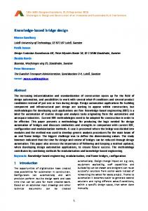
inertial effects. The fin ite element method consists in solving numerically a nonlinear part ial d ifferential equations system of motion in space-time do main coupled with constitutive laws and appropriate boundary conditions. First, the partial differential equations problems with boundary conditions are reformu lated in a weak form assuming an admissible displacement. The, the spatial discretizat ion leads to set of algebraic equations time dependant for crash problems. This set of second order differential equations in time is then solved by discretizat ion in the time domain. For the simu lation of dynamic problems such as crash analysis, the time discretizat ion is one of the major points that can strongly influence the accuracy and efficiency of the algorithm. The two main solution procedures are the explicit and implicit algorith ms. The imp licit scheme is unconditionally stable. But it has two main drawbacks: the first one is that a linear set of equations must be solved repeatedly so the computation time increases with the size of the model when using a direct solver. The second one concerns convergence which is sometimes hard to reach. In general fin ite element code dedicated to the simulation of transient dynamic phenomena such as crash or impact (e.g. Radioss, Altair Hyperworks, Mich igan, USA), the temporal exp licit scheme is used. Explicit nu merical time schemes such as the well-known central difference scheme have been widely used as they do not require numerical iterat ions at each time step, and also for their good properties in term of accuracy and robustness with possible nonlinearities. The state of the system is evaluated at each time step. The state at a given time t, is used to calculate the state at the time t + Dt where Dt is representing the time step. Furthermore, the inert ia and mass of the system are taken into account. The explicit scheme is a specific method where the equilibriu m state is evaluated at a time where displacements are already known at each point of the mesh. In this process, displacements are known at the time where the dynamic equilibriu m of the system is solved, and needs only the inversion of the mass matrix. Furthermore, if a lu mped mass matrix scheme is used, the mass matrix is diagonal and does not need inversion. The resolution of the system is very quick since each degree of freedo m is calculated separately. Each stress is evaluated in each element indiv idually. At each time step, the state of equilibriu m is updated, which corresponds to the propagation of a wave into the element. Th is important point leads to the conditional stability of the scheme, which means the existence of a critical t ime step for the stability of the resolution. For high speed simulations, temporal discretizat ion can be performed by the central difference methods (CDM). In such explicit time integration method, specific conditions on the maximal t ime step for nu merical stability are assumed. Th is time step also depends on the number and the type of elements used to model the system. In automotive industry, FE models are developed using 4 nodes shell elements [25]. This requirement means that, during one time step, the distance travelled by the fastest wave in the model should be smaller than the smallest
57
characteristic element size in the mesh, representing the shortest length for a wave arriving on a node to cross the element. For examp le, with elements of 5 mm, and for a typical steel material law, this condition leads to an order of magnitude of 10-3 ms. Indeed with this order of magn itude of the time step, it appears that this specific scheme is an appropriate method to solve very rapid phenomenon, with high velocity leading to non highly non linear problems. For typical impact duration of 100-200 ms, it appears necessary to use this kind of integration scheme for an accuracy of the results. This time step also depends on the number and the type of elements used to model the system. In automotive industry, FE models are developed using 4 nodes shell elements (BELYTSCHKO, T.; TSA Y, C.S., 1981). The following picture illustrates a FE model of a window, developed with shell elements.
6. Interconnection Design/Crash Using Knowledge Configuration Management: An Example In this section we d iscuss about an examp le of crash simu lation integration in the design process using collaborative approach. Indeed, the SIA trophy is an automotive challenge for auto motive designers, manufacturers, universities, whose aim is to build and design a vehicle able to face to today’s new specifications in terms of innovations, respect of the environment. The main idea in UTBM Team is to be able to design a new a vehicle each year using the knowledge capitalised by the previous teams. Teams are composed of students, thus each year the turnover of the team is 100% off. In this context, the concept of Knowledge management, using KCModel, for design and simulat ion of crash is appeared like well appropriated. Thus, as specified in section 1, nu merical simu lation has been used throughout the design process: trade-off, pre-sizing and sizing. Different types of finite element analysis were done to design the new vehicle (thermal analysis, acoustic, etc.) and were exploited at the same time in a concurrent design context. Figure 11 illustrates this interconnection and mo re especially the pre-sizing phase to illustrate collaboration and impacts between the expert domains. Thus, for each expert do main, CAD-CAE integration (used in early design stage) allows to improve the new design choices through short loops of design and simulat ion process. For examp le, new frame design was test in simulat ion and analysis results allow giv ing design reco mmendations. Nevertheless, each expert domain used heterogeneous design and simulation tools and need to share parameters and constraint (mathemat ic relations, boundary conditions, etc.). Consequently, they use knowledge configurations management method to check conflicts and to control the impact of each design choices on the others expert do mains. For example, cy linder block model (expert domain 1) needs
58
J. Badin et al.: Knowledge Based Simulation Driven Design for Crash Applications
to share parameters with frame model (expert domain 3) and they have to be sure that design choices of each of them do not generate conflicts in the design process. The finite element simulat ion of crash is introduced in the expert domain 3. The simu lation was perfo rmed to design the body and the frame o f the new vehicle. CAD geo metry models (Figure 11) have been used to generate the mesh. The bodywork and the frame of the vehicle have been modelled with solid parts into CA D software, in taking into account their thickness. Mid-surfaces of the bodywork and of the
Figure 11.
frame have been ext racted in order to mesh them with 4 nodes shell elements as recommended for a crash FEA, and illustrated in Figure 11. In this experiment, the use of knowledge configuration into several loop of design and simulat ion models, allows to better take into account of constraints and improve collaboration. It also helps to better consider every technical choice fro m each expert area despite their heterogeneity and diversity and avoid conflict in the design process that can result in lost time, increased cost and lower p roduct quality.
CAD-CAE integration using knowledge management approach
Toward a new generation tool : KCManager
Methodology KCMethod
Figure 12.
Metamodel KCModel
Demonstrator ADES
synoptic representation of this research work
International Journal of M echanics and Applications 2012, 2(5): 49-60
In results of this experiment, we estimate that using simu lation/design integration and knowledge management in configurat ion allows saving 50% t ime in the design process than classical approach. In this way we consider our proposition that can be defined as highly productive and collaborative. It is now necessary to treat other industrial cases to confirm our results and define more specific indicators to evaluate the gains in the design process. We will also improve this approach on cases fro m of different industrial domains, not just automotive.
7. Conclusions The main objective was to underline the strong interconnection between a specific type of numerical simu lation – crash - , and the design process especially in very complex field the automotive design. It concerns the appearance of a vehicle, governed by important kinds of parameters factors including security, safety and engineering - all of which have their own set of specialists. In this context, an approach to manage knowledge using configurations synchronized with expert models which enable designers to use parameters consistently in a collaborative context seems to be necessary. This kind of approach can substantially reduce develop ment time and costs. About our knowledge management work, the main results of our research are structured around three axes (Figure 12) : • A methodology for knowledge configuration management qualified as KCMethod. • A meta-model, called KCModel, structuring concepts man ipulated by KCMethod. • A model of feasibility, namely ADES software tool, allo wing testing and validation our approach. The overall results are articulated around a next-generation software solution, described as KCManager, in order to deploy the approach proposed in Figure 2 across the company. The KCModel and the presentation/experiment of ADES will be presented in a next paper.
REFERENCES [1]
K. Aman, 2010. The Growing Importance of Simulation Analysis in Product Development. Congres NAFEM S, France.
[2]
R. D, 2010. Leveraging Simulation for Competitive Advantage, BOEING Company. Congres NAFEM S, France.
[3]
[4]
Y. Weng, , X. J in, Z. Zhao, Y. Cao, J. Wang, 2010. Grid-based collaborative simulation system for vehicle crashworthiness. Simulation M odelling Practice and Theory. 18(6), pp.752-767. R. Burman, 1992. Designing for minimum lead times.
59
Automotive Eng. 17, p.61. [5]
B. L. M iles, K. G. Swift, 1992. Working together. M anufacturing Breakthrough. 4, p.69.
[6]
R. T. Yeh, 1992. Notes on concurrent engineering. IEEE Trans. Knowledge Data Eng. 4, p.407.
[7]
C. M erlo, PH. Girard, 2004. Information system modelling for engineering design co-ordination. Comput. Ind. 55, pp.317-334.
[8]
G. Sohlenius, 1992. Concurrent engineering. CIRP Annals M anufacturing Technology. 41(2), pp.645-655.
[9]
S.C-Y Lu, W. Elmaraghy, G.Schuh, R. Wilhelm, 2007. A Scientific Foundation of Collaborative Engineering. CIRP Annals - M anufacturing Technology. 56(2), pp.605-634.
[10] G. Pahl, W.Beitz, J. Feldhusen, K.H. Grote, 2007. Engineering Design: A Systematic Approach. Springer. [11] S.Gomes, J.-C. Sagot, 2002. A concurrent engineering experience based on a cooperative and object oriented design methodology. In Best papers book from 3rd International Conference on Integrated Design and M anufacturing in M echanical Engineering. [12] N. Prasad, E. Plaza, 1996. Corporate M emories as Distributed Case Libraries. In: Proceedings of Knowledge Acquisition Workshop, Banff, Alberta, Canada. [13] R. Holt; C. Barnes, 2010. Towards an integrated approach to “Design for X”: an agenda for decision-based DFX research. Research in Engineering Design., pp.123-136. [14] J. Badin, D. M onticolo, D.Chamoret, S. Gomes, 2011. Knowledge configuration management for product design and numerical simulation. In: 18th International Conference on Engineering Design (ICED11). [15] S.Charles, B. Eynard, 2005. Specification of Simulation Data M anagement Environment Integrated with PDM. In: Samuel, Andrew (Editor); Lewis, William (Editor). ICED 05: 15th International Conference on Engineering Design: Engineering Design and the Global Economy. Barton, A.C.T.: Engineers Australia. [16] L. Louis-Sidney, V.Cheutet,; S.Lamouri, O.Puron, A. M ezza, 2011. A design logistics support tool on an operational level. In: 21st CIRP Design Conference, KAIST, Daejeon, Korea, 27-29, 2011. [17] A.Bouras, B.Gurmoorthy, R.Sudarsan, 2005. Product Lifecycle M anagement: emerging solutions and challenges for Global Networked Enterprise PLM -SP1, 2005. [18] B.Eynard, S.Liénard, S.Charles, A.Odinot, 2005. Web-based Collaborative Engineering Support System: Applications in M echanical Design and Structural Analysis. Concurrent Engineering. 13(2), pp.145-153. [19] M .Grundstein, 2009. GAM ETH: a constructivist and learning approach to identify and locate crucial knowledge. International Journal of Knowledge and Learning. 5(Number 3-4). [20] C.Deck, R. Willinger, 2008. Improved head injury criteria based on head FE model. International Journal of Crashworthiness. 13(6), pp.667-678. [21] A.Eskandarian, D.M arzougui, N. E. Bedewi, 1997. Finite element model and validation of a surrogate crash test vehicle for impacts with roadside objects. International Journal of Crashworthiness. 2(3), pp.239-258.
60
J. Badin et al.: Knowledge Based Simulation Driven Design for Crash Applications
[22] S. Roth, J.-S. Raul, and R. Willinger. 2010. Finite elements modelling of paediatric head impact. Global validation against experimental data. Computer M ethods and programs in Biomedicine 99, pp.25-33. [23] H. A. Whitworth, R Bendidi, D M arzougui, R Reiss, 2004. Finite element modeling of the crash performance of roadside barriers. International Journal of Crashworthiness. 9,
pp.35-43. [24] T.Belytschko, W.K. Liu, B. Moran, 2000. Nonlinear Finite Elements for Continua and Structures. Wiley [25] T. Belytschko and C.S. Tsay, Explicit Algorithms for Nonlinear Dynamics of Shells, in Nonlinear Finite Elements Analysis of Plates and Shells, ed. by Hughes, T. J. R., ASM E, New York, 1981, pp. 209-231