ISPC «Modern information and electronic technologies» UDC 621.38
LABVIEW MONITORING OF A SYSTEM FOR SOLAR POWERED STREET LIGHTS M. Sci. M. Misković, M. Sci. M. Milivojević, Dr. Z. Stević, Dr. N. Rajaković, Dr. B. Reljin School of Electrical Engineering, Innovation center of School of Electrical Engineering, University of Belgrade Serbia
[email protected];
[email protected];
[email protected];
[email protected];
[email protected] The monitoring of electrical parameters of an autonomous solar power system for street lighting is presented in this paper. Monitoring system is based on LabVIEW virtual instruments and NI USB 6009 module for signal acquisition. The relevant voltages were monitored in day and night conditions, and the results were analyzed in order to optimize the parameters and to test the functionality of the charge controller and protection circuitry. Keywords: Solar energy, LabVIEW VI, energy efficiency. National energy policy goals today are going towards in terms of reducing the electricity production costs (investment and exploitation), as well as environment protection. The need to reduce the fossil fuels share and to strengthen environmental awareness provides a place for renewable energy [1]. In the first place, photovoltaic (solar) panels, due to their technical characteristics and price drop. In addition to solar power plants that are connected to the grid, photovoltaic (PV) panels are adequate for isolated (autonomous) power consumers, which become more and more prominent need of modern civilization. This paper presents a model of the solar power systems of the public lighting in the conditions when the distribution network infrastructure is hard to reach. In such a system the power is supplied from the photovoltaic panels and the whole system is autonomous. In order to promote this form of electricity generation, the necessary data were measured and collected using LabVIEW software to determine the energy efficiency of the elements required for such a system. The system consists of a photovoltaic panel, a battery, a battery charge controller, a power relay and a light source. The breakthrough in solar cell technology production, regarding the ratio of the active surface of photovoltaic modules and its coefficient of utilization, in recent years has been significant [2]. This is reflected not only in the technical-technological innovative operation, but also in specific drop of prices on photovoltaic panels, which now range up to 2 €/W. The photovoltaic panel that is used in this system is a monocrystalline panel of 12 V nominal voltage with the power of 120 Wp. Calculation of the average hourly electric power at the terminals of the PV panel:
PPV = η ⋅ A ⋅ I PV where η is efficiency ratio of the PV panel, A — active area of the PV panel, IPV — total mean irradiation on the surface area of the PV panel. The battery pack is the most important part of the autonomous power supply lighting system. It depends on the battery, if the power be constantly provided. Today a large number of batteries is produced with different characteristics that in the choice of battery impose a numerous dilemmas. The rechargeable battery that was used in this case was the sealed lead acid battery VRLA (Valve Regulated Lead-Acid). In open or conventional lead-acid batteries water loses should be regularly compensated, which is not necessary (nor possible) for the VRLA batteries. That is why they are often called maintenance-free batteries. Voltage level of the system is 48 V. In order to make the system of more realistical size, 4 serially connected batteries of nominal voltage of 12 V and 12 Ah capacity were used. These batteries, given the strength of the light source (the consumer), provide 2 days of autonomy, provided that the lamp operates 12 hours a day, which is the case in the winter time. Battery charge controller is an electronic device that regulates the charging voltage battery. It controls charge current to avoid the so-called "over current" overcharge and damage to the battery, which among other
Odessa, 27 — 31 May, 2013 – 125 –
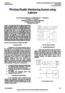
ISPC «Modern information and electronic technologies» things, extends battery life. Electronic relay is a device used to break or establish a circuit, which, depending on the available energy by priorities will include or exclude load. Load is the LED light source. LED generation lamps represent a major step in the development of energy efficiency and environmental responsibility systems [3]. Low power and long life of these light sources, with high-efficiency photometric systems, significantly saves the cost compared to conventional sources. Additional savings can be achieved by using dimmers and remote control systems. In this system, an LED light source with the power 25 W is used (fig. 1).
Fig. 1. Testing circuitry
Signal acquisition For successful signal acquisition, basically a proper signal conditioning is needed [4]. The values of voltage from V0 to V7 and the values of current from I0 to I3 (Fig. 1) are being measured in the system. Also, the values of voltage and current intensity do not exceed 50 V and 5 A, respectively. The voltage values are measured directly, while the current intensity is measured indirectly. In this measurement system, the current is converted into voltage by a shunt resistor. Shunt resistance is 0.24 Ω, the value of voltage is in order of volts. Since the point of reference potential (common ground) in the system is not derived, the voltage at the shunt resistor cannot be measured in differential mode. For this reason, the potentials of all resistors lead to separate signal conditioning circuit. The purpose of this circuit is twofold. The first step is to scale the value of the potential (48—52 V) by voltage divider by a factor of 11 to a value that is in the input voltage range of acquisition card (± 10 V). In parallel with this resistor, a capacitor of 100 µF is connected. Because of the characteristics of the power control system (switching mode), the effect is pulse current. Since the current is not constant over time, but is present in the waveform strong fluctuations, the parallel combination of capacitors and a resistor forms an integrator with a time constant in order of the tenth of a second. Thus, the other circuit function is implemented for the conditioning that mitigates the electricity dynamic structure (signal averaging) so that the signal acquisition would provide the desired results. The other end of the resistor is connected to a common end that is further attached to the ground of the acquisition device. Total number of voltage divider is eight. These voltages are then fed to the single mode analog input acquisition card marked with AI0 to AI7. The acquisition card NI (National Instruments) USB 6009 [5] is connected via the USB interface to the PC. For each channel the sampling frequency of 5000 Hz is defined. The software of the acquisition system was designed in the LabVIEW ® 2010 software package [6]. Еhe scheme implemented in the block diagram forms the values of current and voltage on the basis of the measured values. The acquisition card in a virtual domain creates a multiplex signal, which demultiplexes into eight independent sequences that correspond to voltages and are further processed. The first block in the chain of signal processing presents averaging of the input string to the length of 100 samples (at certain time the system takes as input all 100 samples). Therefore, the measurement errors are reduced. Further on, at the averaged value the additive constant is added. In the first measurement these constants are set to zero. Since the input voltage is scaled version of the original (splitter divides the signal voltage by 11) each sequence is multiplied by 11 (this is also the initial value). After these operations, the obtained sequences correspond to the voltage V0 to V7 and they are displayed in the appropriate numerical indicators on the front panel of the VI instrument. Each pair of eight voltages subtracts, and the difference is divided by the value of the shunt resistor (0.24 Ω) and finally derives the current value I0 to I3 indirectly (Fig. 2). The front panel (Fig. 3), current time diagrams are set. The time scale division is one minute. During continuous measurement, the value at a given time is shown on the diagram and on the numerical indicators. In accordance with the expected current values, certain scale is set at the y-axis.
Odessa, 27 — 31 May, 2013 – 126 –
ISPC «Modern information and electronic technologies»
Fig. 2. LabVIEW application
Fig. 3. Front panel
The calibration of the system is done at the first (test) measurement and involves two phases. In the first phase, the zero values are attached at the input of the acquisition card (short-circuit analog input and ground). Due to system offset measured value will not be equal to zero. If that measured value is multiplied by -1 and the new value is now the value of the additive constant (initially constant equal to zero), in that case the measured value of the voltage can be as close to zero as possible. The second phase involves correcting multiplicative constants that are initially equal 11 (decline voltage divider). In this case, using the reference instrument (physical voltmeter), the value of the voltage at the appropriate point is measured. Ratio between this value and the value that is indicated by the virtual instrument defines a correction factor for the multiplicative constant. System is calibrated and therefore prepared to fully exploit. In addition to the time chart and numerical indicators that show the momentary values of voltage and current, all values are written to a text file every second. It is allowed that the user chooses the path and name of the text file at the program start. Each row contains the time information, in seconds, followed by the measured current intensity and voltage data. Results and discussion The light meter was used (FS1108 Elcom) to measure the level of illuminance E (lx). The initial (zero) measurement point occurred at 16 h 06.03.2013. In Fig. 4 the first graph shows the values recorded by the light meter (typical for rainy day 1500—15000 lx). Night period starts around 120th minute. The graph below in Fig. 4, the voltage at the ends of photovoltaic panels with nominal 12 V slowly decreases to 0, as the sunset
Odessa, 27 — 31 May, 2013 – 127 –
ISPC «Modern information and electronic technologies» begins. Since there are no options for (automatic) switching, V2 and V4 have the same values. Electronic relay P2 disconnects customers if the battery voltage falls below the allowed value (10.5 V). For lead VRLA battery, nominal voltage of 12 V (6 cell nominal voltage of 2 V), manufacturer specifies the Ah capacity that will discharge the each battery cell voltage to 1.75 V, therefore the battery voltage after a full discharge is 10.5 V. At this point, an electronic relay turns off further consumption in order to protect the battery from excessive discharge. The electronic relay is programmed to turn back on the consumer after. After 60 minutes, the battery electrolyte is stabilized, the battery is shortly recovered and the consumers are involved.
Fig. 4. Time diagrams of illuminance and relevant voltages
After comparing the displayed graphics it can be concluded that the proper conditioning of the signal was generated. These signals are suitable for further processing and manipulation in order to comprehend the energy efficiency of the elements of the system for conversion of solar energy for public lighting power supply purposes. ______ The authors gratefully acknowledge financial support from the Ministry of Education and Science, Government of the Republic of Serbia through the Projects IP 1/33 a n d O I 172060. REFERENCES 1. Joe D. Guggenberger, Andrew Curtis Elmore, Mariesa L. Crow, Predicting performance of a renewable energy-powered microgrid throughout the United States using typical meteorological year 3 data // Renewable Energy.— 2013.— Vol. 55.— P. 189—195. 2. Khouzam K., Khouzam L. Load prioritization and shedding in photovoltaic power systems // Solar Cells.— 1991.— Vol. 31, Iss. 6.— P. 505—511. 3. http://www.elcombgd.rs/repository/files/02streetLED.pdf 4. Scholz F. Electroanalytical methods: guid to experiments and application, Web reference: http://www.chemweb.com/arforms?fid=31 5. http://www.ni.com/pdf/manuals/371303m.pdf 6. National Instruments LabVIEW, Analysis concepts; NI Corporation, 2010. ___________
М. Mишкович, М. Mиливоевич, З. Стевич, Н. Раякович, Б. Релин Мониторинг системы уличного освещения от солнечной энергии при помощи LabVIEW. Описан контроль электрических параметров автономной системы солнечной энергии для освещения улиц. Система мониторинга основана на виртуальных приборах LabVIEW и модуле NI USB-6009 для обнаружения сигнала. Соответствующие напряжения наблюдались в дневных и ночных условиях, и результаты были проанализированы с целью оптимизации параметров и для проверки работоспособности регулятора и защиты. Ключевые слова: cолнечная энергия, LabVIEW VI, энергоэффективность.
Odessa, 27 — 31 May, 2013 – 128 –