Oct 8, 2006 - Yong-Duk Kim, Bum-Joo Lee, Jeong-Ki Yoo, Jong-Hwan Kim, and Jee-Hwan Ryu. Abstract-For the purpose of a humanoid robot's stable.
2006 IEEE International Conference on Systems, Man, and Cybernetics October 8-11, 2006, Taipei, Taiwan
Landing Force Controller for a Humanoid Robot: Time-Domain Passivity Approach Yong-Duk Kim, Bum-Joo Lee, Jeong-Ki Yoo, Jong-Hwan Kim, and Jee-Hwan Ryu Abstract- For the purpose of a humanoid robot's stable walking or running, it is important to absorb landing force or ground reaction force which is generated when the robot's foot lands on the ground surface. The force can make the robot unstable, and the problem becomes serious if the robot runs. This paper proposes a control system, which can absorb the landing force of a humanoid robot. Time-domain passivity control approach is applied for this purpose. Ground and the robot's foot are modeled as two one-port network systems, which are connected and exchange energy with each other. The time-domain passivity controller has the landing force as input and controls the foot's position to reduce the force. The proposed controller can guarantee the stability of the robot system without need of any dynamic model information or control parameters. Using small sized humanoid robot, dynamic walking experiments are performed to verify the proposed scheme, and its efficiency is shown from the comparison with the other scheme.
I. INTRODUCTION Many research groups in the world are currently working on humanoid robots and there are many successful projects [1], [2], [3], [4]. Current research, being conducted in collaborating operations with human beings [5],[6], has progressed far beyond studies in walking trajectory generation [7],[8] and online (real-time) balance control [9],[10] during walking. But the basic and most important function of the humanoid robot is the ability to walk safely in the real environment. For a stable walking, it is important to absorb either landing force or ground reaction force, which is produced when the robot's foot lands on the ground surface. The force can make the robot unstable during walking, and if the robot runs, it becomes a serious impediment for
maintaining stability.
Several researchers have studied the hybrid impedance and computed torque control, and the hybrid position and force control for the impedance adjustment of the leg LI5],[16]. In this situation, however, the complex dynamics of the robot must be known, apart from it being difficult to find control parameters. In addition to these, there is a study which tries to decrease the landing force using a special foot structure
[17].
This paper proposes a novel controller to compensate the landing force of a humanoid robot. Time-domain passivity approach [18],[19] is implemented for this purpose. The robot's foot is modeled as a one-port network system, which has the landing force as an input, and foot's position as an output. By calculating the energy input into the one-port network based on the landing force and the foot position, the robot's foot is controlled to absorb the landing force. The proposed control method can guarantee the stable dynamic walking without any model information and control parameters, which must be determined by calculation or trials and errors. Moreover it requires very little additional computation. The validity of the proposed control method is confirmed through dynamic walking experiments using the small-sized humanoid robot, HanSaRam-VI. The efficiency is also shown from the comparison between the proposed scheme and the other one. The remainder of this paper is organized as follows. In Section II, the small-sized humanoid robot, HanSaRam-VI, is described. Section III presents the modeling of robot's foot system which consists of robot's foot and ground surface, and the time-domain passivity control is proposed to compensate the landing force. Section V presents the experimental results of the proposed method. Finally, conclusion follows in Section VI.
In a typical human locomotion, leg muscles are repeatedly hardened and relaxed depending on the walking pattern phase [11]. Once the muscles that move the leg hit the ground, II. HUMANOID ROBOT HANSARAM-VI they tend to be softer for a while to reduce the forces. In order to maintain support, they get harder again and this TABLE I process is repeated in over and over again. For a walking SPECIFICATIONS t)F HANSARAM-VI or running robot, several approaches have been studied to DOF Link Length ]j Joint reduce contact force. Some heuristic approaches have been ~~~~~~~. 3 (x2) 60 Hip between [mm] hip joints Length used to shift the foot position once it reaches the surface 1 (x2) Knee 100 [mm] Length of thigh [12], [13], [14]. However, there are problems in changing 2 (x2) Ankle 100 [mm] Length of shank 1 the foot position and PID controller coefficients voluntarily. 40 [mm] Waist Length between ankle and sole Shoulder 3 (x2) 100 [mm] Length between toe and heel *-
Width of foot
Yong-Duk Kim, bum-Joo Lee, Jeong-Ki Yoo, and Jong-Hwan Kim
are with the Robot Intelligence Technology Laboratory, Dept. of EECS, KAIST, Guseong-dong, Yuseong-gu, Daejeon, 305-701, Republic of Korea
{ydkim,bjlee,jkyoo,johkim}@rit.kaist.ac.kr
Jee-Hwan Ryu is with the School of Mechanical Engineering, Korea University of Technology and Education, Cheoan-city, 330-708, Republic
of Korea j hryu@kut . ac . kr
1-4244-0100-3/06/$20.00 C2006 IEEE
Length of lower trunk
Length of upper trunk Length between shoulder joints Length of upper arm Length of lower arm
4237
60 [mm] 100 [mm] 100 [mm] 160 [mm] 97 [mm] 86 [mm] I ------I -
-
-
Elbow Wrist Total
\
-
I
-
1 (x2) 2 (x2)
25
Fig. 2. One-port network model.
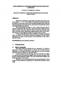
Fig. 1.
HanSaRam-VI.
Fig. 1 and Table I show a small-sized humanoid robot, HanSaRam-VI and its specification. It has 25 DOFs, and consists of 12 DC motors in lower body and 13 RC servo motors in upper body. Its height and weight are 52 cm and 4.5 kg, respectively. This biped robot's structure is mainly composed of Duralumin. Even though HanSaRam-VI is a small humanoid robot, the design of the lower body is focused on generating sufficient power and accurate control, and therefore consists of DC motors and Harmonic drives. In the design of the upper body, 13 RC servo motors are used, due to light weight and easy to control. The on-board Pentium-IlI compatible PC with running RTLinux calculates the walking pattern in real time. The walking pattern is generated on-line based on three-dimensional inverted pendulum model [20]. The stand-alone vision system using PDA is equipped to find out three colored objects in real time. To measure forces on the foot, 4 FSRs are equipped on each foot. With the help of all the computational and power parts, HanSaRam-VI has the ability for fully independent sensing, processing, and locomotion.
First, we define the sign convention for all forces and velocities so that their product is positive when power enters the system port. Also, the system is assumed to have initial stored energy at t = 0 of E(0) (Fig. 2). Following variables for force and position are defined during one sample time tk 1 < t < tk for the sampled time system: 1) f(t) = F(k) is the force at k, which is constant during one sample time, tk-1 < t < tk. 2) x(k) and x(k- 1) are the positions at k and k- 1
sample times, respectively. Then, the passivity of the sampled system can be defined as the following: Definition 1: The one-port network N with initial energy storage E(O) is sampled time passive if and only if k
E(k) =
,: F(j')(x(j)-x(j-1)) + E(O) > O
j=o
(1)
where j 0,1, 2, .. ., k 0,1, 2, .. ., for sampled force F(j) and position x(j). Note that if E(k) > 0 for every k, this means the system dissipates energy. If there is an instance that E(k) < 0, this means the system generates energy, and the amount of generated energy is -E(k). B. Modeling robot's foot system Foot
III. LANDING FORCE CONTROLLER USING TIME-DOMAIN PASSIVITY APPROACH
A. The time-domain passivity In this section, we briefly review time-domain passivity concept before it is implemented for absorbing the landing force. Recently, the sampled time passivity concept has been proposed in [21], because many of the input and output variables in control problems can be measured by computer, and the conjugate variables which define power flow in such a computer system are sampled time values. The robot control system to compensate the landing force is assumed to take a force as an input, and computes foot's position as its output. Typically, this input force is measured by force sensors and used through AD converter at each sample time. And the computed position output is applied to a motor controller so that motors can follow reference position continuously.
f
A1
tx
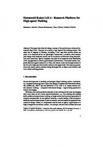
Ground (a) Robot's foot and ground sur- (b) One-port network face. models of the robot's foot and ground surface Fig. 3. Robot's foot system modeling.
To implement the time-domain passivity approach, the robot's foot and the ground are modeled as a network system. Both systems can be modeled as one-port network systems, which are connected each other. Fig. 3 shows the real and the
4238
modeled network system, respectively. The sign convention for force and velocity is defined so that the energy is positive when the power enters the system port of the robot's foot. In Fig. 3(b), the force and the velocity are positive in the upper direction. Since the ground can be considered as an intrinsically passive system, the connected system (the robot's foot and the ground) can be passive if the robot's foot, the one port network, is passive. This is a situation where the foot is physically absorbing the contact force. Once we prove the passivity, stability of the robot system can be also guranteed because passivity is a sufficient condition of stability. On the other hand, when the robot's foot, one port network, is active (while the input energy is negative), the robot might be unstable. This is the case when the robot's foot kicks the surface, which causes a big landing force between the foot and the ground. This force is the main reason for the unstable walking. Therefore, a control algorithm is required for alleviating the landing force. C. Landing force controller
Ax
The proposed time-domain passivity control system consists of a passivity controller (PC) and passivity observer (PO), which controls and monitors the input/output energy flow between the robot's foot and the ground. Passivity observer computes the energy flow using the landing force and the foot position as follows:
W(k) = W(k -1) + f, (k)(xi (k) - xi (k - 1)) (2) Wo(k + 1)
=
W(k) + fi (k)(x2(k + 1)
-
xi (k))
(3)
where W(k) is the total energy output from 0 to k, and Wo(k + 1) is the prediction of the one-step-ahead energy output. The last term of Eq. (3) is the estimation of the onestep-ahead energy output, which is the output energy from k to k + 1. Note that we know the planned position x2(k + 1) at step k. If the PO can predict whether the system at the next step will be passive or not at the current step k, the PC can modify the desired position at the next step (k + 1) to make the system passive. The PC absorbs exactly the net energy output (if any) measured by the passivity observer at each time sample. Based on the PO (steps 4 and 5 below), the PC algorithm (steps 6 and 7 below) for the one-port robot's foot is developed as follows: 1) f1 (k) = f2(k) is the input; 2) Ax, (k) = xi (k) - x1(k - 1) AX2(k + 1)= x2(k + 1) - xi(k); 3) AX2(k) is the output of the one-port network; 4) W(k) = W(k- 1) + f1 (k) Ax, (k) is the energy output at step k 5) Wo(k+1) = W(k)+fi(k)Ax2(k+i1) is the prediction of the energy level at step k + 1 6) The PC output for making the system passive is calculated as follows:
3~~
Robot r ----------------------,1 I I
f,
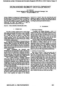
Fig. 4.
One-port network with P0/PC.
We can divide the one-port network of the robot's foot system into two parts: mechanism part with low-level position controller and planner part with high-level controller. Fig. 4 shows the separated network system of robot's foot. f ( fi f2) iS the landing force, which can be measured by the FSR sensors on the robot's foot. x is the actual height position of the robot's foot, and A\x is the difference between two consecutive sampled data of x. The modified position (x1) is obtained from the originally planned walking pattern (x2) and the output of the passivity controller (Sxpc). x2 is a planned height position of walking pattern from the walking pattern planner, which did not consider the landing force from the ground. If we use the planned walking pattern, the robot's foot might get a big landing force from the ground in a very short time, and it makes the one-port of the robot's foot active. In order to reduce the landing force, the passivity controller is attached to modify the planned walking pattern (x2) to x1 by adding 6xp. Therefore, the robot takes the ground reaction force into account and it can make a contact to the ground more securely.
f-W,,(k+1)
if W0(k + 1) < 0 if Wo(k + 1) > 0
r 10 7) The modified desired height position can be calculated from Ax, (k + 1) = AX2 (k + 1) + 3xpc (k). It should be noted that the PO/PC is for achieving the stable landing of humanoid robot. Once the stable landing is achieved (maintaining N steps with positive energy, where N is constant.), the robot's walking path should be modified to follow the initially planned walking path. The walking pattern, changed by the passivity controller, is interpolated to the initially planned walking pattern by using the polynomial method. In this stage, passivity observer is also reset to prepare the next observation. IV. EXPERIMENTS Dynamic walking experiments were performed to verify the proposed time-domain passivity control approach. The results are compared with those using no landing force
control and the heuristic control to absorb the force. In the experiments, the biped robot walked with a speed of 4 cm/s
4239
and a step length of 3 cm. Double and single support phases of a step were 0.15 s and 0.6 s, respectively. All experimental results are plotted after the initial 2 seconds of operation and then for 5 seconds thereafter.
A. Walking experiments without landing force control Left foot position Ir1! --~ I
2.5
3
3.5
4
5 4.5 Time (sec)
I
5.5
6
6.5
7
Fig. 5. Foot's height position without landing force control.
foot landed on the ground, it was bounced back from the ground instantaneously due to the big landing force such that it disturbed stable dynamic walking. During the support phase, there were two large peaks at the start and end of supporting time. The first peak was caused by the foot's landing at the beginning of the double support phase and the second peak came from the another foot's landing at the start of the next double supporting phase. It should be noted that two force plots are different because the mass distribution was asymmetric in the real robot. Fig. 7 shows the input energy from the one-port robot's foot. When the foot kicks the surface, the energy becomes negative and the robot's foot is no longer passive. It means that the robot might be unstable due to this active energy output from the foot. B. Walking experiments with the heuristic method In the second experiments, the controller made the robot shorten the legs when the huge force was detected as follows [14]: a (f)v
\ Left foot force
Z
+ (1
-
o(f ))(-wAX)
(4)
where Ax is the modification of the foot height and f is the force. The control mode is switched by the function of u(f) (Fig. 8). In the experiments, v and w were selected as 12 and 30, respectively.
30
a)
Y 20
LL
10
0L
2
40L 40r
2' 30! 2 20
LL
10I0
Fig. 6. Force without landing force control.
Fig. 8. Switching function for the heuristic method.
LeR foot energy
Left foot position with hueristic -
-0.2
-;--0.4
2
2.5
3
3.5
4 5 4.5 Time (sec) Right foot energy
55
6
6.5
tL 0
7
2
2.5
3
305
4 4.5 5 5.5 Time (sec) Right foot position wih heuostic r--r-
--T
2
2.5
3
3.5
4
4.5 Time
(sec)
5
5.5
6
65
6
6.5
7
6
6.5
7
v
7 2
2.5
3
3.5
4
4.5
lime (sec)
5
5.5
Fig. 7. Energy without landing force control.
First, the experiments were performed without landing force control. Fig. 5 shows the walking trajectory without considering landing force. When robot's foot was landing, there was a big landing force as shown in Fig. 6. This force caused 'double contacts' of the foot. Even after the robot's
Fig. 9. Foot's height position with the heuristic method.
Fig. 9 shows the foot was moved upward a little to absorb the landing force. The amount of displacement is plotted in Fig. 10 and Fig. 11 indicates the force was reduced relatively in comparison with the previous result. But, from the energy
4240
Delta z with heuristic
E
_
21
Fig. 10.
Ax
with the heuristic method.
Fig. 12. Energy with the heuristic method. Left foot force with heuristic
Left foot position with PO/PC
2'
2
2.5
3
3.5
Right
40
4
5 4.5 Time (sec)
5.5
5 4.5 Time (sec)
5.5
6
6.5
7
6
6.5
7
foot position with PO/PC
30'
Z
2 20.
LL
10 Time
(sec) 2
Fig. 11.
2.5
3
3.5
4
Force with the heuristic method.
Fig. 13. Foot's height position with PO/PC.
view point, it is not enough to meet the passive condition, as shown in Fig. 12. The energy was still active. Thought the heuristic method could reduce the force somewhat, it was too difficult to obtain a reasonable control parameters (v, and cX(f)) for the experiments. It needed many trials and errors experiments.
equations are not used any more in the proposed method. Moreover, control parameters are not required.
w,
C. Walking experiments with the PO/PC Fig. 13 Fig. 16 show the results when the proposed timedomain passivity controller was implemented. The modified walking pattern is plotted in Fig. 13. Foot is slightly moved upward on each landing time, since the passivity controller modified the planned walking pattern to satisfy the passivity condition. After 10 steps in which the energy stays positive, it was shifted to its original planned position by cubic spline interpolation. As shown in Fig. 14, the force was remarkably reduced because the passivity controller immediately reduced the force. There was no presence of 'double contact' any more. Fig. 16 shows the robot system's energy. Due to the bigger force than the value which PO initially estimated, the system could not be passive. But the result indicates the scale of negative energy decreased by 1, 000 times, and the system was controlled to satisfy the passivity condition by 5 steps (0.025rns). The results of the overall experiments indicate that the proposed passivity controller absorbs the impulsive landing force at the ground surface effectively and makes stable foot landings passible. It is important to note that system dynamic -
V. CONCLUSION
For a stable dynamic walking or running of humanoid robot, the control of the landing force is indispensable. This paper proposed the novel controller to compensate for the landing force. For the use of the time-domain passivity approach, the ground and the robot's foot were modeled as two one-port network systems, which are connected and exchanging energy each other. The time-domain passivity controller, which has the force as an input and controls the foot's position to reduce the force, was implemented. The proposed scheme was verified with the developed smallsized humanoid robot, HanSaRam-VI. The efficiency of the proposed scheme was shown in the comparison with the experimental results of the scheme without landing force control and of the heuristic scheme. The proposed method could stabilize the landing motion of the biped robot. Besides, it could guarantee the stable dynamic walking without any system model information or control parameters at all. ACKNOWLEDGMENT
This work was supported by the Ministry of information & Communications, Korea, under the Information Technology Research Center (ITRC) Support Program.
4241
Left toot force with PO/PC r--
Lefttfoot deHta PC with PO/PC
--i
I
0.4
Z30.
° 0.2
205
a)
40
___
0
Z 3-
2
Time (sec) Right foot force with PO/PC
_
501-
0'
-E
30' 20
Fig. 14. Force with PO/PC. x
lo-,
4
2
2.5
3
3.5
4
45
5
5.5
6
6.5
7
4.5 5 Time (sec)
5.5
6
6.5
7
Time (sec) Right foot delta PC with PO/PC
0.4
Fig. 16.
T---
-
IA
---
r
--
__
uJ
[11] 1- ,-3 2.5
2 x
10t3
1,
3.5
4
i----
4.5
L _,_,
5
Time (sec)
5.5
6
65
7
[12]
Right foot Energy with PO/PC
E
5
[13] 2
bx
with PO/PC.
[10] B.-J. Lee, Y.-D. Kim, and J.-H. Kim, "Balance control of humanoid
_
ifI
m
35
Left foot Energy with PO/PC
r-
V
LD
3
-sa
LL
-10
2.5
-
40 z
2
2.5
3
3.5
4
4.5
5
5.5
6
6.5
7
lime (sec)
Fig. 15. Energy with PO/PC.
REFERENCES
[1] K. Hirai, M. Hirose, Y. Haikawa, and T. Takenaka, "The development of honda humanoid robot," in Proc. of IEEE Int. Conf. on Robotics and Automations, Leuven, Belgium, May 1998, pp. 1321-1326. [2] Y. Ogura, Y. Sugahara, Y. Kaneshima, N. Hieda, H.-O. Lim, and A. Takanishi, "Interactive biped locomotion based on visual/audiotory information," in Proc. of IEEE Int. Workshop on Robot and Human Interactive Communication, Berlin, Gemany, Sept. 2002, pp. 253-258. [3] S. Kagami, K. Nishiwaki, J. J. Kuffner., Y. Kuniyoshi, M. Inaba, and H. Inoue, "Online 3d vision, motion planning and bipedal locomotion control coupling system of humanoid robot H7," in Proc. of IEEE Int. Con on Intelligent Robots and Systems, vol. 3, Lausanne, Switzerland, Oct. 2002, pp. 2557-2562. [4] J.-H. Kim, D.-H. Kim, Y.-J. Kim, K.-H. Park, J.-H. Park, C.-K. Moon, K. T. Seow, and K.-C. Koh, "Humanoid robot hansaram: Recent progress and development," J. of Advanced Computational Intelligence & Intelligent Informatics, vol. 8, no. 1, pp. 45-55, Jan. 2004. [5] S. Setiawan, S. Hyon, J. Yamaguchi, and A. Takanish, "Physical interaction between human and a bipedal humanoid robot," in Proc. of IEEE Int. Conf on Robotics and Automation, vol. 1, Detroit, MI, May 1999, pp. 361-367. [6] K. Harada, S. Kajita, F Kanehiro, K. Fujiwara, K. Kaneko, K. Yokoi, and H. Hirukawa, "Real-time planning of humanoid robot's gait for force controlled manipulation," in Proc. of IEEE Int. Conf on Robotics and Automation, vol. 1, New Orleans, LA, Apr. 2004, pp. 616-622. [7] S. Kajita, A. Kobayashi, and T. Yamamura, "Dynamic walking control of a biped robot along a potential energy conserving orbit," IEEE Trans. on Robotics and Automation, vol. 8, pp. 431-438, Aug. 1992. [8] Q. Huang, K. Yokoi, S. Kajit, K. Kaneko, H. Arai, N. Koyachi, and K. Tanie, "Planning walking patterns for a biped robot," IEEE Trans. on Robotics and Automation, vol. 17, no. 3, pp. 280-289, June 2001. [9] J. Yamaguchi, E. Soga, S. Inoue,, and A. Takanishi, "Development of a bipedal humanoid robot control method of whole body cooperative dynamic biped walking," in Proc. of IEEE Int. Conf on Robotics and Automation, vol. 1, Detroit, MI, May 1999, pp. 368-374.
[14]
robot for hurosot," in Proc. of IFAC World Congress, Prague, Czech, July 2005. C. Leonard, Gait Analysis: Theory and Application, R. L. Craik and C. A. Oatis, Eds. Mosby-Year Book, 1995. Q. Huang, K. Kaneko, K. Yokoi, S. Kajita, T. Kotoku, N. Koyachi, H. Arai, N. Imamura, K. Komoriya, and K. Tanie, "Balance control of a biped robot combining off-line pattern with real-teim modification," in Proc. of IEEE Int. Conf on Robotics and Automation, vol. 4, San Francisco, CA, Apr. 2000, pp. 3346-3352. F Silva and J. Machado, "Position/force control of biped walking robots," in Proc. of IEEE Int. Conf. on System, Man, and Cybernetics, vol. 5, Nashville, TN, Oct. 2000, pp. 3288-3293. S. Kajita, T. Nagasaki, K. Kaneko, K. Yokoi, and K. Tanie, "A running controller of humanoid biped hrp-21r," in Proc. of IEEE Int. Conf: on
Robotics and Automation, Barcelona, Spain, Apr. 2005,
pp.
618-624.
[15] J.-H. Park, "Impedance control for biped robot locomotion," IEEE [16] [17]
[18]
[19]
[20] [21]
4242
Trans. on Robotics and Automation, vol. 17, no. 6, pp. 870-882, Dec. 2001. H.-O. Lim, S. Setiawan, and A. Takanishi, "Position-based impedance control of a biped humanoid robot," Advanced Robotics, vol. 18, no. 4, pp. 415-435, 2004. J. Yamaguchi, A. Takanishi, and I. Kato, "Experimental development of a foot mechanism with shock absorbing material for acquisition of landing surface position information and stabilization of dynamic biped walking," in Proc. of IEEE Int. Conf. on Robotics and Automation, vol. 3, Nagoya, Japan, May 1995, pp. 2892-2899. B. Hannaford and J.-H. Ryu, "Time-domain passivity control of haptic interfaces," IEEE Trans. on Robotics and Automation, vol. 18, pp. 110, Feb. 2002. J.-H. Ryu, D.-S. Kwon, and B. Hannaford, "Stability guaranteed control: time domain passivity approach," IEEE Trans. on Control Systems Technology, vol. 12, pp. 860-868, Nov. 2004. S. Kajita, F. Kanehiro, K. Kaneko, K. Fujiwara, K. Yokoi, and H. Hirukawa, "Biped walking pattern generation by a simple threedimentional inverted pendulum model," Advanced Robotics, vol. 17, no. 2, pp. 131-147, 2003. J.-H. Ryu, Y.-S. Kim, and B. Hannaford, "Sampled- and continuoustime passivity and stability of virtual environments," IEEE Trans. on Robotics, vol. 20, no. 4, pp. 772-776, Aug. 2004.