5th World Conference on Structural Control and Monitoring
5WCSCM-179 5WCSCM-001
LARGE-SCALE CAPACITANCE SENSOR FOR HEALTH MONITORING OF CIVIL STRUCTURES S. Laflamme Massachusetts Institute of Technology, Cambridge, MA 02139, USA
[email protected] M. Kollosche University of Potsdam, Potsdam, 14469 Germany
[email protected] J. J. Connor Massachusetts Institute of Technology, Cambridge, MA 02139, USA
[email protected] G. Kofod University of Potsdam, Potsdam, 14469 Germany
[email protected] Abstract In this paper, a new type of sensing technique for damage localization on large civil structures is proposed. Specifically, changes in strain are detected using a capacitance sensor built with a soft-stretchable dielectric polymer with attached stretchable metal film electrodes. This sensor is sensitive to a change in strain that causes a change in its capacitance. Fixed to a structure, small changes in the strain can be monitored directly by measuring the change in the capacitance of the unit. This technology allows for simple yet highly accurate measurements of cracks occurring due to deformation, aging, or other structural failures. The proposed system deploys a layer of dielectric polymer on the surface of a structural element, and regularly monitors any change in the structural state. The smart material is composed of inexpensive silicone elastomers, which make the monitoring system a promising application for large surfaces. Tests on concrete beams show that the sensor is highly sensitive to strains induced by flexural cracks, and is capable of detecting localized micro-fractures over its covered area.
Introduction Structural health monitoring (SHM) is expected to play a predominant role in infrastructure and building management to cope with aging structures and the recent heightened public awareness concerning safety. It has been shown that the difference in risk between infrastructures and air or automobile travel is of an order of magnitude higher, because: 1) infrastructure play a key role in society and has a paramount economical value; 2) infrastructure is not heavily tested; and 3) infrastructure has a long life span, and is designed based on load assumptions and predictions (Karbhari, 2009). The field of structural health monitoring has recently attracted much attention (Song, et al. 2007). Emphasis has been placed on non-destructive evaluation, leading to a wide variety of nondestructive testing techniques such as pulse-echo, dynamic response, and acoustic emission (Bungey et al. 2006). However, the application of these methods is very often temporary and localized because of the technical constraints due to equipment limitations and costs associated with these various strategies. Consequently, most of these methods, despite the fact that they are well understood and provide an acceptable accuracy, are difficult to implement for a large-scale structure. As a result, monitoring of civil structures is commonly done by visual inspection, which can be costly and time consuming. Various SHM techniques have been developed for civil structures over the last decade. SHM is an integrated process consisting of sensing and data processing that leads to damage localization. The main problem in locating damage, which becomes more difficult as the number of degree-of-freedom and degree of indeterminacy increases. Some SHM techniques focus on damage localization, and typically include static sensing strategies, such as static strain gauges. These techniques are typically precise at localizing damages, but need to be deployed over the entire monitored system (analogous to
Laflamme, Kollosche, Connor and Kofod
1
a human skin) in order to be capable of complete health diagnosis. Needless to say, typical complete SHM systems rapidly become economically unfeasible as the scale is increased. Current sensing technologies include fiber optic, resistance strain gauges, piezoelectric transducers, and piezoelectric polymers (PVDF). Embedded fiber optic and piezoelectric materials sensors can be efficient at damage localization, however, due to the embedding, these devices are typically costly to install, inherently weakens the material at a certain level and sensor replacement is almost impossible. Ceramic piezoelectric wafer active sensors (PWAS) can be either attached to the surface of a structure, or embedded. They permit several non-destructive evaluation methods, such as pitch-catch, pulseecho, phased array (Lin, et al., 2007). Thus, they can monitor the material by wave propagation similar to the conventional ultrasonic transducers. Challenges in using conventional PWAS are bounding with the monitored surface and their durability. Zou et al. (2005) have applied an external strain sensing system to a pipeline to monitor buckling. The challenge in monitoring pipelines is somewhat similar to monitoring cracking in concrete in the sense that point sensors are not sufficient. They used fiber optic sensors applied along the pipeline, secured externally. The disadvantage is that the bounding surface may induce impedance in the system, thus creating noisy data (Lin, et al., 2007). Other disadvantages of fiber optic include reduction of spatial resolution with increased number of cracks, and cable recoverability which may lead to loss of accuracy (Chen, et al., 2005). Piezoelectric polymers typically have high compliance, can be manufactured in thin films, are lowcost, and easy to fabricate. Their applications include: keyboards, headphones, speakers, and highfrequency ultrasonic transducer (Giurgiutiu, 2009). The most widely known PVDF sensors have been shown to be more cost-effective than strain gauges, and require smaller power (Zhang, Lloyd, & Wang, 2003). The performance of PVDF at high frequencies has been assessed and shown to be good at detecting damages, while Zhang et al. (Zhang et al., 2003) studied the effect at low frequencies. They have used patches of 19 x 5.1 mm (0.75 x 0.20 in).The design showed to be suitable for SHM. One of the major disadvantages of PVDF is that they are significantly sensitive to the quality of the bound to the applied surface due to the nature of the dynamic signal. Research is currently being done to overcome the issue. Lin et al. (2009) developed a fabrication technique to apply the PVDF sensor directly on the structural substrate. Recent advances include piezoelectric paints which are easily spreadable over an entire structure (Zhang, 2005). Also thin-film nano-PWAS composites with sensors distributed directly in the substrate have been demonstrated, and are characterized by their low power requirement for pulseecho detection of cracks (Yu & Giurgiutiu, 2009). In this paper, the authors have developed a novel monitoring technique capable of detecting changes in strain on large surfaces at low cost. The sensor consists of a soft capacitive material highly sensitive to strain. Unlike resistance-type strain gauges, it does not require high power to operate, which allows for application to large surfaces. The sensor is also economical, and easily converts strains into significant changes in capacitance, which results in simple data processing for damage localization. Furthermore, unlike dynamic strain gauges, it can be easily applied on irregular surfaces. The paper is organized as follows. The next section describes the proposed monitoring technique. The following section shows test results on reinforced mortar and concrete specimens. The last section contains conclusions Proposed Monitoring Technique The sensor proposed for monitoring cracks over wide areas is a soft capacitance sensor. The next subsection explains the use of capacitive sensors for strain sensing, while the subsequent section describes the proposed sensor.
Laflamme, Kollosche, Connor and Kofod
2
Capacitive Sensors Capacitive sensors typically consist of two highly compliant electrodes having a surface A which are separated by a distance d. Their compliance C is given by: 𝐶 = 𝜀𝑟 𝜀0
(1)
𝐴 𝑑
where 𝜀𝑟 describes the relative permittivity of the medium between the electrodes and 𝜀0 the permittivity of the vacuum. Capacitance units can be designed for elastic deformation using a polymer material covered with stretchable electrodes. Figure 1 shows a sketch of such a capacitive unit. The polymer can be viewed as a deformable layer which acts as a separator for both electrodes.
Figure 1. Sketch of a capacitive unit, showing the sandwich structure of compliant electrodes surrounding an electrically insulating elastomer layer of thickness d.
The deformation of the sensor leads to a direct change in capacitance. Figure 2 schematizes the mechanism of the sensor.
(a)
(b)
Figure 2. (a) Capacitive sensor bounded to the monitored structure; (b) local deformation resulting in a local change of the electrode area A+ΔA.
Proposed Sensor The proposed sensor uses the principles explained in the previous subsection. The first prototype was constructed using a commercially available capacitive sensing material, the PolyPowerTM manufactured by Danfoss Polypower. PolyPowerTM consists of a silicon elastomer in conjunction with a smart metallic compliant electrode technology (Benslimane, Gravesen, & Sommer-Larsen, 2002). The smart electrodes are deposited by a sputtering process, capable of producing a metal electrode much thinner than the elastomer film. They are patterned with a corrugating pattern, which makes the material very stiff in the direction perpendicular to the corrugations, and highly compliant in the direction along the corrugation. The silicone elastomer (PDMS) has a relative permittivity of 𝜀𝑟 = 3.1 and film thickness 𝑑 = 40 µm, while the laminated compliant silver electrodes have a thickness 100 nm (Kiil & Benslimane, 2009). The unique aspects of their material are the uniformity of film thickness, and the long term stability of the conductive electrodes along with their capacity to withstand very large displacements. Figure 3 shows a roll of PolyPowerTM material. Laflamme, Kollosche, Connor and Kofod
3
Figure 3. roll of PolyPower
TM
material (200 mm wide).
Interestingly, any flexible polymer material with appropriate metallization e.g. silver, nickel, gold, could be used to construct a stretchable capacitance sensor. As stated above, the commercially available material PolyPowerTM is highly stretchable, on the order of 30%, but the utilization of a material of lesser elasticity would still be feasible for monitoring of civil structures because of the inherent small deformations. This would result in an improved mechanical robustness and ease of installation on rough surfaces. The measurement method utilized for the prototype is the comparison mode. The comparison mode consists of measuring the difference of capacitance between two sensors: a sensing capacitance Csense, and a referential capacitance Cref. This technique has the advantage of a higher resolution in measurements, provided that both sensors have initial capacitances of comparable magnitude. In the comparison mode, the capacitive sensor can be compared with a capacitive sensor of any material, but in order to control for environment effects such as temperature drift, the sensor is herein compared with a similar capacitive sensor. The location of the referential capacitance can be selected by the monitoring system designer. One strategy, termed double layered differential sensor, locates the referential capacitance located directly on the top of the sensing capacitance, strategy. Figure 4 illustrates that concept. The use of soft glue with thickness 500µm damps the strain signal form the sensing capacitor to the reference capacitor Cref and therefore increase signal in the proposed differential mode.
Figure 4. Sketch of a double layered differential sensor separated by a soft visocelastic glue of thickness 𝒅∗ = 500µm.
The deployment of the sensor on the monitored structure is straightforward. The importance of the bounding agent is minimized as shear lag is not an issue for static measurements. However, when measurements are taken continuously, it is recommended that a stiff epoxy be used. That allows deformations arising from cracks to be quickly transferred to the sensors, resulting in a significant jump in the measurements. Otherwise, that change in differential capacitance will show as a slope if a flexible bounding agent is utilized. Laflamme, Kollosche, Connor and Kofod
4
Sensor Sensitivity In the following, the measurement sensitivity of the capacitive strain sensor is analyzed, to establish the smallest detectable change in sensor strain 𝑆. The smallest detectable length change is then calculated for the sensor setup used in this study. The differential sensing system consists of a sensing capacitor 𝐶sense and a reference 𝐶ref, which for simplicity are assumed to be initially identical. The thickness of the sensor is denoted 𝑑, the length 𝑙 and the width 𝑤. Due to the aforementioned corrugations, the width 𝑤 will not change during deformation. On the other hand, since the elastomer is incompressible, length and thickness are coupled directly, as will be exploited shortly. Hence, the capacitance of the sensing film is 𝐶sense = 𝜀𝑟 𝜀0 𝑤𝑙/𝑑, and a change in this capacitance may be calculated as a total differential (for small changes): 𝜕𝐶sense 𝜕𝐶sense 𝜕𝐶sense ∆𝐶sense = ∆𝑙 + ∆𝑤 + ∆𝑑 (2) 𝜕𝑙 𝜕𝑤 𝜕𝑑 Thus, the relative change in capacitance is: ∆𝑙 ∆𝑤 ∆𝑑 + − 𝐶ref 𝑙 𝑤 𝑑
∆𝐶sense =
(3)
As mentioned, due to the corrugations, it can be assumed that ∆𝑤 = 0. The conservation of volume 𝑉 = 𝑙 ∙ 𝑤 ∙ 𝑑 leads to the following relationship for the deformed state: 𝑙 ∙ 𝑤 ∙ 𝑑 = 𝑙 + ∆𝑙 (𝑑 + ∆𝑑)𝑤
(4)
∆𝑙 ∆𝑑 =− 𝑙 𝑑
(5)
leading to the following relation:
Combining (3) and (5), the change in capacitance with sensor strain is found to be: 𝑆=
∆𝑙 ∆𝐶sense = 𝑙 2𝐶ref
(6)
The dimensions of the sensors utilized in the experiments are 50 x 60 mm. Initially, the capacitances of these sensors are 2058 pF (Equation (1)). The manual for the data acquisition device (ACAM PSØ21) indicates that for 𝐶ref = 2 nF and a measurement frequency of 10 Hz, the smallest detectable capacitance change is 𝛿 ∆𝐶sense = 25 fF, which corresponds to a strain resolution of 𝛿(𝑆) = 𝛿 ∆𝐶sense/2𝐶ref = 6 ppm. For the sensors employed here, with 𝑙 = 60 mm, the length resolution becomes 𝛿 ∆𝑙 = 0.4 μm, which is below the micrometer range. Also, using (1) and (6), one can obtain a general expression for change in capacitance of the sensor due to a length change: ∆𝐶sense 𝜀𝑟 𝜀0 𝑤 =2 ∆𝑙 𝑑
(7)
Equation (7) illustrates that the sensitivity increases with sample width and inversely to sample thickness, as expected. Also, it is seen that the sensitivity may be improved by raising the permittivity of the elastomer, which can be achieved by blending the material with carbon black nanoparticles (Stoyanov 2009) .
Laflamme, Kollosche, Connor and Kofod
5
Tests A first series of tests have been conducted at the University of Potsdam. This section shows and discusses the results from two representative tests: a mortar specimen where the reference sensor is not attached on the beam (herein referred as test #1), and a concrete specimen with a double layered differential sensor (herein referred as test #2). Both tests consist of inducing flexural cracks (4-points load) in specimens using periodic loadings. A constant load is applied for a set period of time, and then released in order to simulate the load/no-load conditions, where the no-load condition is the 50 N plateau. The value of the constant load is increased every steps by 50 N increments, using a constant loading rate of 50 N/min. The objective of the periodic loading tests is to look at the capability of the sensor to detect cracks, and the periodic load ensures that the changes in measurements are not a result of changes in curvature from an applied load. The differential capacitance is measured by an ACAM PSØ21 capacitance comparing amplifier. This amplifier can accurately measure in the range of 10-15 F to 10-9 F (ACAM Mess Electronic). In the comparison mode, the PSØ21 device minimizes parasitic effects of connections and capacitive units in the circuit board to improve measurement accuracy. Figure 5 shows the setup for the test.
Figure 5. Experimental setup; the sensor is located under the beam.
The sensors are placed on the bottom of the beam to locate flexural cracks. To glue the sensor to the beam, the surface is initially sanded, and a layer of primer is painted before applying the stiff epoxy. The installation is quite straightforward, which shows that the technology can be easily implemented on large-scale specimens. Figure 6 shows the sensor installed on the beam. The loading and displacement rates are plotted against the capacitance measurement, and a jump in the loading and displacement rate is taken as the apparition of a crack if cracks could not be confirmed by visual inspection.
Laflamme, Kollosche, Connor and Kofod
6
Figure 6. Picture of the sensor applied on a beam.
Test #1 For the first test, the sensor dimension is 50 x 60 mm. The specimen is a low-resistance mortar (high water ratio), 70 x 50 x 370 mm. Figure 7a) is a plot of both sensor strain (relative change in capacitance) and displacement rate against time. Data clearly show a jump in the differential capacitance by a factor of 2 when the first crack appears independently of the loading condition. Note that there was a loss of data between the range 415 sec - 730 sec due to a software failure. Figure 7b) is a blow up of the first jump in capacitance measurement. It can be observed that there is a jump in the displacement rate at the same time, thus the formation of a crack. Figure 7c) is a blow up of the region following the crack appearance. It can be observed that the differential capacitance is sloping upwards, representing a loss in stiffness in the beam.
crack
(a)
Laflamme, Kollosche, Connor and Kofod
7
crack widening
first crack
(b)
loss of stiffness
(c) Figure 7. Differential capacitance and displacement rate against time. a) time history; b) blow up on the first crack; c) blow up on loss of stiffness.
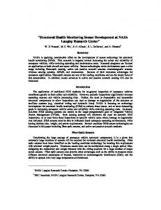
Test #2 For this test, a double layered differential sensor is used (see Figure 4). Figure 8 shows the differential sensor on the concrete beam. The sensor is attached on the bottom of the concrete beam, 70 x 50 x 370 mm, to detect flexural cracks. Figure 9 is a graph of the sensor strain (relative change in capacitance) along with the loading rate. The loading rate is plotted instead of the displacement rate (test #1) as it depicted clear jumps at the formation of cracks. It can be observed that the sensor is sensitive to the micro-crack formation. The micro-crack formation is deduced from the minor jump in the loading rate. The sensor also clearly detects the first crack as observed with the jumps in the capacitance measurement and the loading rate. A second crack is also detected from the measurements following a loss of stiffness. Laflamme, Kollosche, Connor and Kofod
8
Figure 8. Double layered differential sensor.
second crack loss of stiffness
first crack micro-crack
(a)
jump in capacitance measurements
jump in loading rate
(b) Figure 9. Differential capacitance measurement with loading rate; a) time-series; b) zoom on the first crack region. Laflamme, Kollosche, Connor and Kofod
9
Conclusion A new method for damage localization on large-scale structures has been proposed. The SHM technique detects changes in strain using a capacitance sensor built with a soft-stretchable dielectric polymer with attached stretchable metal film electrodes. The smart material is composed of inexpensive silicone elastomers, which makes the monitoring system a promising low-cost application for large surfaces, and easy to apply. Results from tests showed promising performance for the proposed sensor. Tests on reinforced mortar and concrete specimens demonstrated that the sensing strategy is clearly capable of accurately detecting small cracks in concrete specimens. Acknowledgements
The authors thank Andreas Pucher for valuable help with the measurement setup. M. Kollosche and G. Kofod acknowledge support from the WING initiative of the Germany Ministry of Education and Research through its NanoFutur program (Grant No. NMP/03X5511). References ACAM Mess Electronic. (n.d.). Retrieved April 28, 2010, from ACAM Manual 2007: www.acam.de Benslimane, M. Y., Gravesen, P., & Sommer-Larsen, P. (2002). « Mechanical Properties of Dielectric Elastomer Actuators with Smart Metallic Compliant Electrodes”. Proc. SPIE , 4695, 150-157. Bungey, J., Millard, S., & Grantham, M. (2006). Testing of Concrete in Structures (4th edition ed.). New-York: Taylor and Francis. Chen, G. D., Sun, S. S., Pommerenke, D., Drewniak, J. L., Greene, G., McDaniel, R. D., et al. (2005). “Crack Deterction of a Full-Scale Reinforced Concrete Girder with a Distributed Cable Sensor”. Smart Materials and Structures , 14, S88-S97. Giurgiutiu, V. (2009). “Piezoelectricity Principles and Materials”. In C. Boller, F.-K. Chang, & Y. Fujino, Encyclopedia of Structural Health Monitoring (pp. 981-991). Wiley. Gu, H., Jin, P., Zhao, Y., Lloyd, G. M., & Wang, M. L. “Design and Experimental Validation of a Wireless PVDF Displacement Sensor for Structure Monitoring”. Proc. SPIE Nondestructive Detection and Measurement for Homeland Security II , 5395, 91-99. Guy, P., & Monnier, T. (2006). “Structural Health Monitoring with Piezolectric Sensors”. In D. Balageas, C.-P. Fritzen, & A. Güemes, Structural Health Monitoring (pp. 287-365). ISTE. Jia, Y., & Sun, K. (2006). “Thick film wireless and powerless strain sensor”. Proc. SPIE , 6174, 61740Z 1-11. Karbhari, V. M. (2009). “Design Principles for Civil Structures”. In C. Boller, F.-K. Chang, & Y. Fujino, Encyclopedia of Structural Health Monitoring (pp. 1467-1476). 2009. Kiil, H.-E., & Benslimane, M. (2009).”Scalable Industrial Manufacturing of DEAP”. Proc. SPIE , 7287, 0R. Lin, B., Giurgiutiu, V., Bhalla, A. S., Chen, C., Guo, R., & Jiang, J. (2009). “Thin-Film Active Nano-PWAS for Structural Health Monitoring”. Proc. SPIE Sensors and Smart Structures Technologies for Civil, Mechanical, and Aerospace Systems , 7292, 1-11. Lin, B., Giurgiutiu, V., Yuan, Z., Liu, J., Chen, C., Jiang, J., et al. (2007). “Ferroelectric Thin-Film Active Sensors for Structural Health Monitoring”. Proc. of SPIE , 6529, 1-8. Song, G., Gu, H., Mo, Y., Hsu, T., & Dhonde, H. (2007). “Concrete Structural Health Monitoring Using Embedded Piezoceramic Transducers”. Smart Materials and Structures , 16, 959-968. Straser, E., & Kiremidjian, A. (1998). A Modular, Wireless Damage Monitoring System for Structures. The John A. Blume Earthquake Engineering Center. Stoyanov, H, McCarthy, D., Kollosche, M., Kofod, G. “Dielectric properties and electric breakdown strength of a subpercolative composite of carbon black in thermoplastic copolymer” Appl. Phys. Lett. 94, 232905, 2009. Todd, M. D. (2009). “Data Interrogation Approaches with Strain and Local Gauge Sensor Arrays”. In C. Boller, F.-K. Chang, & Y. Fujino, Encyclopedia of Structural Health Monitoring (pp. 277-288). Wiley. Yu, L., & Giurgiutiu, V. (2009). “Piezoelectric Wafer Active Sensors”. In C. Boller, F.-K. Chang, & Y. Fujino, Encyclopedia of Structural Health Monitoring (pp. 1013-1027). Wiley. Zhang, Y. (2005). “Piezoelectric Paint Sensor for Real-Time Structural Health Monitoring”. Proc. of SPIE , 1095-1103. Zhang, Y. (2009). “Piezoelectric Paint Sensors for Ultrasonics-based Damage Detection”. In C. Boller, F.-K. Chang, & Y. Fujino, Encyclopedia of Structural Health Monitoring (pp. 1037-1049). Wiley. Zhang, Y., Lloyd, G. M., & Wang, M. L. (2003). “Random Vibration Response Testing of PVDF Gages for Long-Span Bridge Monitoring”. In F.-K. Chang, Structural Health Monitoring 2003 (p. DEStech). 115-122. Zou, L. F., Bao, X. Y., Ravet, F., & Chen, L. (2005). “Prediction of Pipeline Buckling using Distributed Fiber Brillouin Strain Sensor”. In J. P. Ou, H. Li, & Z. D. Duan, Structural Health Monitoring and Intelligent Infrastructures (pp. 393396). Taylor & Francis.
Laflamme, Kollosche, Connor and Kofod
10