Large-Scale Cooperative Relaying Network with Optimal Coherent Combining under Aggregate Relay Power Constraints Peter Larsson, Ericsson Research. Ericsson AB, S-164 80 Stockholm.
[email protected] Abstract - Communication schemes exploiting cooperating relay nodes can enable significant SNR and diversity order enhancements. In this paper, a communicating pair of nodes with support from an arbitrary number of relay nodes cooperating in parallel is considered, and the optimal weighting parameters for coherent combining based non-regenerative relaying are derived under aggregate relay power constraint. The analysis demonstrates that each relay merely requires multiplying the received signal with an individual phase and amplitude factor and a common amplitude normalization factor. It is illustrated that the resulting SNR is substantially enhanced compared to direct communication and that SNR improves with increasing relay station density. I. Introduction Cooperation among nodes in a wireless network can enhance communication performance, both with respect to mean signal to noise ratio (SNR) as well as to diversity order. This has been shown in several recent papers, which are extensions and modifications of the classical information theory relay channel [1]. Cooperation between two transmitting nodes sending towards a single receiver has been studied in [2]-[3]. The transmitting stations exchange their data and transmit their own as well as the other station’s data. For this purpose, both repetition and spacetime coding has been considered. A similar topology, but with two receivers and without internal cooperation, is studied in [4]. Other cooperative schemes assume only one transmitter and one receiver, but exploit multiple relays. This scenario is of somewhat more practical interest, since two adjacent stations will fairly seldom have data to send concurrently. This idea is exemplified by the concept in [5], and methods presented in [6]-[10]. Large, and perhaps unrealistic, amount of bandwidth for orthogonal relay channels is required in [5], but it is well suited for MIMO communication. The latter, [6]-[10], uses the same channel for all relayed signals and opt for various diversity techniques. Of particular interest is [9] and [10], by Schein, where a two relay node case with coherent combining in a real valued channel is considered. Under individual relay power constraints, Schein argues for a power setting where one relay uses its maximum power and the other with less than its constraint, thereby enabling SNR maximization. However, the optimal parameter settings and the resulting optimal SNR are not derived, nor is a more realistic complex channel considered. Coherent combining based cooperative transmission has also been considered in [11], but only for so-called regenerative relaying and with identical transmit powers, i.e. only co-phasing of signals. For the area as a whole, both regenerative (decode and forward) and non-regenerative relaying (amplify and forward) has been considered in forwarding the received signal. While regenerative relaying is beneficial in that it
Transmitter
Link 1
h1,1
PTX
h1, 2
TX
Relays
n RS ,1
RS1
n RS , 2
RS2
h1, K
∑
Pk
k =1
P2
PK
K
PRS =
Link 2
P1
n RS , K
Receiver
h2,1 h2, 2 h2, K
RX
n RX
RSK
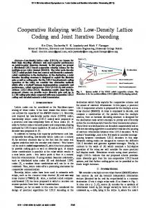
Fig. 1. System model does not induce any noise per se, it is typically limited to shorter distances due to the requirement of decoding before relaying. On one hand, fixed relays are of interest as they can be positioned to offer good propagation conditions, e.g. with line of sight propagation when either the transmitter or receiver is located higher than the surrounding environment. On the other hand, the concept of mobile relays that may be part of the mobile handsets, is also of interest since large quantities of proximate relays are available. Multihop packet radio networks MPRNs represent yet another architecture that exploits cooperation among relay nodes. While MPRNs can offers interesting advantages, such as SNR enhancements and diversity gains, due to routing “around” obscuring objects and reducing distance for each hop, it is noticed that the topology in [5]-[10] with merely two hops offers similar benefits but (most likely) at a lower complexity. In addition, and in contrast to MPRNs, advanced antenna concepts can be/are an integral part of the latter concept. Here, the general topology of two-hops and parallel relay structure shown Fig. 1., is denoted Cooperative Relaying (or Cooperative Relay Network). A shortcoming of previous work on cooperative relaying is that the analysis has mainly been limited to small networks, with only three to four stations altogether. This limits the potential SNR and diversity gains that could be unravelled if larger number of relays could be exploited. Moreover, optimum power allocation has barely been addressed at all, although touched upon in [10], and in particular with respect to large cooperative networks. In this paper, a large-scale non-regenerative cooperative relay network that uses coherent combining, but under realistic complex valued channel conditions, is examined. The analytical power setting for optimal SNR performance under aggregate relay station power constraint is derived. The rational for constrained power is that the aggregate relay interference and power consumption can be minimized. In section II, the system model is introduced. In section III, the optimal power and phase parameters are derived. Section IV presents some initial performance results and the conclusions in section VI summarizes the work.
II. System Model The communication link, between a transmitter (TX) and receiver (RX), uses K non-regenerative relays (RS) and is modelled as shown in Fig. 1. The transmitter sends a complex Gaussian signal x ~ Ν (0, PTX ) over a frequency flat channels h1,k towards the k:th relay k ∈ {1,2, K , K } where complex Gaussian noise (and interference) 2 nk ~ Ν (0, σ RS , k ) is added. Each relay receives a noisy y k = x ⋅ h1k + n RS , k
signal
and forwards it, after phase
adjustment and power amplification up to power Pk , then denoted z k , over a channel being orthogonal to the receiving channel. This may for instance be achieved through time duplexing1. The channel between relay node k and the receiver has a frequency flat complex channel gain denoted h2,k . Complex Gaussian noise (and interference)
normalized attenuations sum of all k normalized attenuations a k , this is
according to arg{a k } = − arg{h1,k }− arg{h2, k }+ c1 ,
(3) where c1 is an arbitrary constant being set to zero. This is also the basic condition for coherent combining. With
∑ ∀k
is further assumed that power and phase parameters are tuneable in each relay and that antenna gains are included in the channels. III. SNR Optimization In the following, it is assumed that each relay normalizes the received signal (including noise) to unit power and then performs power amplification. To ensure that the aggregate relay transmit power is normalized to PRS , an un-normalized complex help-variable ak is introduced. Such power constraint formulation ease the analysis significantly, in contrast to a Lagrange multiplier based approach. This results in that each station k transmit with power level Pk =
PRS ⋅ a k K
∑a
2
2
2 2 ΓRS , k = h1,k PTX σ RS , k and ΓRX , k = h2, k PRS σ RX , this
may be rewritten in the form
∑a ΓEff =
K
∑a
2
sense that it is the SNR if relay station k would use all aggregate relay stations transmit power by itself. It is observed that (2) has the form
k =1
K
∑a
h1,k
2 q
2
∑a
K
∑ k =1
PRS ak
∑a
K
∑a
⋅ 2
2 PTX + σ RS ,k
q
2 σ RS ,k
h1,k
2
⋅ h2, k
(5)
, 2
⋅ c 2, k
k
which can be transformed by using bk
2
2
= a k ⋅ c2,k and in
turn yielding K
∑b
k
⋅
c 2, k
k =1
ΓEff =
2
c1,k
K
∑b
(6)
.
2
2 PTX + σ RS ,k
. ⋅ h2,k
2
Now, the nominator is upper limited by CauchySchwarz’s inequality K
∑b
⋅
c1,k
2
K
≤
c 2, k
K
∑ b ⋅∑ 2
k
k =1
k =1
c1, k c 2, k
2
,
(7)
For an optimal value of bk , equality can be attained and the resulting SNR is then
2 + σ RX
q =1
The nominator in (2) consists of the sum absolute square of the K relay nodes contribution where; equation (1), the 1
⋅ c1,k
k =1
k
(2)
2
k
k =1 K
ΓEff =
k =1
q =1
Γ=
2
K
k
h1, k ⋅ PTX
⋅
ΓRS ,k + 1
k =1
2
PRS ⋅ ak
(4)
,
Note that ΓRX ,k can be interpreted as a “virtual SNR” in the
k
Using (1) and the assumption of unit power normalized received signal (including noise) power, the SNR at the receiver is
∑
ΓRX ,k + ΓRS , k + 1
⋅
k
k =1
K
2
ΓRS ,k + 1
k =1
(1)
2
⋅
k
k =1
2
.
ΓRS ,k ⋅ ΓRX ,k
K
2 n RX ~ Ν (0, σ RX , k ) is also added in the receiver when the K
superimposed relay signals are received. Moreover, the aggregate relay power, Pk , is a constant denoted PRS . It
useful signals, and the relay to receiver are considered. The denominator contains the relay stations and incorporates equation (1), the relay noise powers, the relay to receiver and the receiver noise. For arbitrary values of maximized through phase alignment of signals
Another option is to include the direct TX to RX link, by phase alignment.
(max) ΓEff
K
=
∑ k =1
c1, k c 2, k
2
.
This can be more conveniently expressed in SNRs as K ΓRS ,k ⋅ ΓRX , k (max) ΓEff = . Γ + ΓRX ,k + 1 k =1 RS , k
∑
(8)
(9)
Trough identification, it is seen that the maximum SNR can be attained if and only if
bk = Const ⋅
c1,k c 2, k
from the receiver. The gain factor common to all relays, i.e.
,
(10)
where Const is an arbitrary constant that is set to one for convenience. Using the reverse transformation, from bk to ak , gives the relation in SNRs ΓRS ,k ⋅ ΓRX ,k ⋅ ΓRS ,k + 1
ak =
ΓRS , k + ΓRX ,k + 1
(11)
.
Using the obtained results, and with some calculation, one can derive that a relay receiving a noisy signal y k should send a signal z k according to z k = yk ⋅
1
⋅
K
∑a
2
PRS ⋅ ΓRS ,k ⋅ ΓRX , k
σ RS ,k ⋅ (ΓRS , k + ΓRX , k + 1)
q
⋅
.
(12)
q =1
⋅e
− j ⋅(arg( h1,k ) + arg( h2 ,k ) )
It is observed that the received signal is multiplied with a relay specific phase factor, and relay specific amplitude factor and normalized with a factor common to all relay stations. The main results here are (9), (11) and (12). As an amendment to the non-regenerative analysis, the regenerative case is now briefly addressed. Following the 2 same procedure, but setting σ RS , k = 0 and arg{a k } = − arg{h2,k }+ c1 when packets can be decoded,
optimal power parameters for regenerative relaying can also be derived. The parameter ak is then a k = ΓRX ,k ,
(13)
and the resulting SNR for mixed non-regenerative and regenerative relaying is then K ΓRS , k ⋅ ΓRX , k , RS k is non - regen. (max) ΓEff = ΓRS , k + ΓRX , k + 1 (14) k =1 Γ , RS k is regen. RX , k
∑
Both the amplitude gain parameters and the SNR contribution for the regenerative case is the same as wellknown coherent combining based transmit diversity [12]. It is also noted that regenerative relying fits well in the framework of non-regenerative relaying, simply by treating it as a special case of the latter. To limit the extent of this study, this track is however not pursued any further. IV. Protocol Architecture Discussion From the foregoing study of optimal transmit parameters, valuable insight in protocol design is gained. First, each relay k has both an amplitude gain and a phase factor that depends on the links for the relay k to the transmitter and the receiver. This suggests that an efficient protocol design would involve exploitation of channel reciprocity where the transmitter as well as the receiver transmits channel estimation symbols prior the data transmission, allowing each relay to determine its specific gain and phase factors. In 2 order to determine ΓRX ,k , the parameters PRS and σ RX (possibly as a ratio) is made known in the relays, either by a priori setting the parameters or informing those by feedback
2
the sum of all aq , is simply a scaling factor that can be informed through feedback from the receiver. Hence the protocol complexity is fairly low, including only two channel estimation symbols sent to the relays from the transmitter and the receiver as well as some low rate feedback from the receiver. Yet, coherent combining based cooperative relaying is not limited to reciprocal channels, but the protocol complexity may increase for other cases. So far, only phase and amplitude control have been considered. As signals traverse different distances via different relays, time offsets will be introduced. One way to address this is to control the signal delay for each relay. However, since this is fairly complex it is instead suggested to use a modulation scheme with a cyclic extension, e.g. OFDM, which is large enough to absorb both delay spread and time offset differences. In this manner, delay control can be mitigated entirely. V. Evaluation As a basic indication on the concept operation and performance, a simple distance dependent path gain model is considered for a square grid relay distribution. The path loss is modelled as hi ,k
2
∝ Ri−,kα , where i ∈ {1,2} , k denotes the
relay, α is the propagation exponent, R is a distance, and the antenna gain is one. The optimum performance is then achieved, due to symmetry reason of (3) and the mesh grid, when PRS = PTX . To illustrate the basic operation, Fig. 2 and 3 shows the normalized relay power distribution for a square grid pattern scenario with 48·48 relays, α = 3 , with a direct transmitter to receiver SNR ΓTX → RX of 0 dB and –40 dB respectively. The relays are placed where the grid lines intersect, whereas the receiver and transmitter are symmetrically located with respect to Y-direction and on opposing sides at a one-quarter distance from their relay grid edges with respect to Xdirection, see Fig. 2. For Fig. 2, it is noticed that a fairly large number of relays are involved in the relaying with similar power levels. A minor bump in between the transmitter and receiver indicate that those relays are fairly active with respect to power, or put another way, they are fairly important relays. More precisely, it is the spatial SNR contribution that decides which relays are the most important ones. It is also observed that the relays closest to the receiver are less active because their contribution to the overall directivity gain is smaller than that of the (larger number of) relays that are concentrically placed further away from the receiver. Yet, at some distance, the path loss in conjunction with the aggregate power constraint deprives the benefit of directivity gain and the relays become less active. In Fig. 3, the SNR is reduced another 40 dB and, as a result, the spatial distribution of power among the relays changes drastically. In contrast to the previous case, the relays that are concentrated around both the transmitter and the receiver are the most active now, due to the limited power budget. An important insight from Fig. 2 and 3 is that this vividly illustrates that there exists locations where a set of antennas (i.e. relays here) can be better exploited than positioning
20
50
40
15
30
10
20
considerable smaller than if large number of relays are used as shown in Fig. 4. This illustrates that exploitation of large number of relays drastically enhance the effective SNR. It is also interesting to note that with coherent combining based non-regenerative relaying, it is possible for the receiver to decode a signal, although the relays themselves may be unable to decode the signal.
30
(Single relay) α = 3 , ΓEff is only 3dB greater than ΓTX → RX , i.e.
25
10
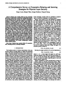
transmitter to receiver SNR ΓTX → RX , i.e. without relays, on the X-axis and the number of intermediate (odd) grid rows of relays between the transmitter-receiver on the Y-axis. To avoid edge effects by the grid, the grid size has been made much larger than the transmitter - receiver distance. As an example, consider a transmitter to receiver SNR of 0 dB, and a relay density corresponding to about eight intermediately placed grid rows, the resulting effective SNR is then 20 dB. Overall, it is noted that very large SNR improvements can be achieved, even in the lower relay density regions, which in turn may be used for range extension or data rate enhancement. The later is either achieved through higher order modulation or bandwidth expansion. The result presented in Fig. 4. can also be compared against a trivial case with a single relay station located just in between the transmitter and the receiver. The corresponding effective SNR for this scenario can be determined from (9) and is 2 2 2α − 2 ⋅ ΓTX (Single relay) → RX ΓEff = α , (15) 2 ⋅ ΓTX → RX + 1 where the power is equally distributed over the transmitter and relay station. For instance, when ΓTX → RX >> 2 −α and
30
20
those at a basestation (as traditional done for some advanced antenna solutions). Also, in contrast to much previous research on cooperative relaying schemes, it is made evident that is not necessarily a matter of always selecting the closest relays. Also note that other parameters change the shape of the power distribution in Fig. 2 and 3, and in particular will fading have impact on the spatial distribution of power. To give a basic performance indication, a contour plot is (max) given in Fig. 4 with α = 3 . It shows ΓEff versus the direct
Fig. 3. Normalized relay power distribution ΓTX → RX = −40dB
Number of (odd) rows of RSs between TX and RX
Fig. 2. Normalized relay power distribution ΓTX → RX = 0dB
40
5 20
-5
0
30
5 10 15 SNR: TX to RX [dB]
20
25
30
Fig. 4. Effective SNR with respect to intermediate number of relays and direct SNR ( ΓTX → RX )
Although this initial performance evaluation is promising in itself, for more conclusive results other but more realistic assumptions must be considered. In particular, channel modelling (e.g. fading) and relay positions (e.g. random) must be examined in greater details. Then, both beneficial macro and micro diversity effects are expected as the optimal power allocation mitigates poor channels per se. It is also noted that the fixed aggregate relay power assumption used here is somewhat pessimistic. A more optimistic assumption would therefore be that PRS ∝ relay density, which implies that the performance could be boosted even further than shown in Fig. 4. In addition to the presented scheme, several extensions are anticipated. Among those, the direct link between the transmitter and receiver can straightforwardly be included in the analysis if desired. There are two options, the direct link is sent in an orthogonal channel relative to the relay to receiver link, or they use the same channel and they are all phase aligned. Studies are currently also ongoing on e.g. relay selection criteria’s, protocols and power control. VI. Conclusions In this paper, a large-scale cooperative relaying scheme based on coherent combining has been proposed. Optimal amplitude parameters are derived under aggregate relay
power constraint. The amplitude parameter contains a relay specific complex amplitude term and joint normalization factor. It is shown that significant SNR gains can be achieved, here illustrated in a simple relay mesh grid pattern, but the performance depends largely on acceptable level of the relay density. An interesting observation is that the spatial distribution of the most power active relays depends on the transmitter to receiver SNR, and simply selecting the closest relays at the receiver or transmitter side is generally suboptimum. VII. Acknowledgment The author would like to thank Kai-Erik Sunell at Ericsson Research for his valuable comments. VIII. References [1]. T.M. Cover and A.A. El Gamal, “Capacity theorems for the relay channel," IEEE Trans. Inform. Theory, vol. 25, no. 5, pp. 572-584, Sept. 1979. [2]. A Sendonaris, Advanced Techniques for NextGeneration Wireless Systems, Ph.D. Thesis, Rice University, August 1999. [3]. J. N. Laneman, Cooperative Diversity in Wireless Networks: Algorithms and Architectures, Ph.D. Thesis, MIT, Cambridge, MA, August 2002. [4]. A. Høst-Madsen: “On the Capacity of Wireless Relaying,” In Proc. VTC’02 Fall, Vancouver, Canada. [5]. M. Dohler, E. Lefranc, H. Aghvami, “Virtual Antenna Arrays for Future Wireless Mobile Communication Systems,” in Proc. ICT2002, June 2002. [6]. J. N. Laneman and G. W. Wornell, "Distributed Space-Time Coded Protocols for Exploiting Cooperative Diversity in Wireless Networks", in Proc. IEEE GLOBECOM’02, Taipei, Taiwan, November 2002. [7]. J. Boyer, D. Falconer, and H. Yanikomeroglu, "A theoretical characterization of the multihop wireless communications channel with diversity", in Proc. IEEE GLOBECOM'01, San Antonio, Texas, USA, November 2001, [8]. M. Gastpar, G. Kramer and P. Gupta. ”The multiplerelay channel: Coding and antenna-clustering capacity.” In Proc IEEE ISIT2002, Lausanne, Switzerland, July 2002. [9]. B. Schein and R. Gallagher, "The Gaussian parallel relay network," In Proc IEEE ISIT2000, Sorrento, Italy, June 25-30, 2000. [10]. B. Schein. Distributed Coordination in Network Information Theory. PhD thesis, pp. 64-68, MIT, Cambridge, MA, August 2001. [11]. Yung-Szu Tu and Gregory Pottie, “Coherent Cooperative Transmission from Multiple Adjacent Antennas To a Distant Stationary Antenna Through AWGN Channels”, in Proc. of IEEE VTC 2002, Birmingham, Alabama, USA, May 6-9, 2002. [12]. H. Vincent Poor and Gregory W. Wornell (Eds): Wireless Communications: Signal Processing Perspectives, Prentice Hall: Upper Saddle River, NJ. 1998. ISBN 0-13-620345-0.