International Journal of Mechanical & Mechatronics Engineering IJMME-IJENS Vol:14 No:04
92
Large-scale Dual Axis Sun Tracking System Modeling and Static Analysis by FEM Fateh Ferroudji1, 2*, Toufik Outtas², Chérif Khélifi¹ and Rafik Mansouri³ ¹Unité de Recherche en Énergie Renouvelables en Milieu Saharien, URERMS, Centre de Développement des Énergies Renouvelables, CDER, 01000, Adrar, Alegria. ²Laboratoire de Mécanique des Structures et Matériaux, Université de Batna 1, Rue Chahid Bouhklouf Mohammed El-Hadi, 05000, Batna, Algeria. ³Département des Sciences de la Matière, Université Africaine, 01000, Adrar, Algeria. E-mail:
[email protected] Abstract— The sun tracking is aimed to optimize the energy production efficiency by following the sun trajectory, and, therefore, the panels must remain always normal to the sun direction. The sun tracking constitute a promising alternative and they are more and more used in industry in order to improve the quantity of the produced power by the photovoltaic systems Tracker performance is impacted from effects such as wind and gravity, and understanding the impact of these loads on the optical performance can yield tracker designs that are potentially cheaper, while maintaining required structural stability. In this paper, A dual axis sun tracking system of 12.8 kWp connected to the grid (the active surface being of 88.5 m²) is modeled geometrically (three dimensional solid model) by using SolidWorks CAD Software and simulated statically by FEA (Finite Element Analysis) using SolidWorks Simulation to determine the equivalent stress, displacement, deformation and safety factor. This approach of design and optimization of the tracking subjected to its free weight and critical wind load, namely wind speed of 130 km/h. Puts forward the interest of this design is to get gain of time, money and the quality of rigidity and resistance of the finished product. Thus, the reliability of the tracking is shown because the critical stresses of Von Mises of the most fragile material check the criteria of resistance with a safety factor higher than six (06) with strains are much lower than the unit. Index Terms— Dual axis sun tracking system, Static analysis, SolidWorks, Wind loads.
I. INTRODUCTION SOLAR Energy is a good choice for electric power generation, since the solar energy is directly converted into electrical energy by solar photovoltaic panels. Dual axis solar tracking system is a key factor for solar PV future and new answers for the solar market. It will develop large scale PV projects worldwide, and it is possible to collect more energy from the sun. The sun tracking follows the sun's path, using a controller, motor, and drive to rotate the PV array (mechatronic systems). That gives between 20% and 50% more energy output than rigid systems in which the panels are installed at a fixed angle of inclination [1-3]. With rapid development in the computer simulation
technology and systems control fields in recent decades, using advanced simulation tools for numerical calculation of structures has become an important research technique and effective way, the literature now contains many sophisticated sun tracking systems designed to maximize the efficiency of solar thermal and photovoltaic systems [4-5]. In this paper, the dual axis sun tracking system [6] as shown in Figure 1 is an electromechanical device. Its top frame of has an attached photovoltaic panels (PV) and the tracking ensures maximum sun exposure on these; this entire structure moves from East to West over an axis that can rotate 240º (azimuthal tracking from 120° to -120° ) and a second axis that can incline 60º to the horizontal position. The azimuth motion is made by a planetary motor reducer over a crown wheel located in the base of the tracking. The elevation motion is made using an electrical jack. During operation, sun tracking system like many engineering structures are subject to static and dynamic loads, because the aerodynamic and gravitational loads vary with time as the tracking rotates. The static analysis objective is to guarantee the strength, stiffness and stability of the structure [7]. Analyzing the external load acting on the structure is first and important for the static analysis. The tracking works in the outdoor environment, so the structure needs withstand, snow load, sand, seismic force and wind load especially strong wind. Knowledge of wind flow is an important success factor of the tracking development. This paper present, modeling and static analysis of a dual axis sun tracking system. The modeling of tracking using 3D computer aided design (CAD) software called SolidWorks. The statics analysis for model has been carried based on SolidWorks Simulation finite element analysis (FEM) software (previously known as COSMOSWorks). This method can find out the equivalent stress distribution, displacement distribution, strains distribution and safety factor of sun tracking under its free weight and wind load critical (high winds), namely winds speed of 130 km/h.
144904-2727-IJMME-IJENS © August 2014 IJENS
IJENS
International Journal of Mechanical & Mechatronics Engineering IJMME-IJENS Vol:14 No:04
93
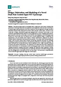
Fig. 1. (Left) dual axis sun tracking Mecasolar MS-2 TRACKER 10+. (Right) Sun tracking MS-2 TRACKER 10+ under installation in Batna, Algeria.
II. THREE-DIMENSIONAL SOLID MODELING OF THE SUN TRACKING IN SOLIDWORKS A three-dimensional (3D) solid model for sun tracking system was built by using the SolidWorks 3D software [8-9]. The sun tracking system is made up by two steel metal substructures. The tracking's central body is made up by a “V” shaped structure on which the frame is installed where the photovoltaic panels are placed. The frame contains sixty PV panels with a capacity of 200 Watts each (the active surface being of 88.5 m²). The configuration is be made in five row of twelve panels and the supporting structure (grid). Another component to be highlighted in the tracking is the hydraulic damper. The 3D solid modeling and the dimensions of the sun tracking are presented in Figure 2. Characteristics for photovoltaic panel of 200 Watts are shown in Table 1. TABLE I CHARACTERISTICS FOR PHOTOVOLTAIC PANEL OF 200 WATTS Parameter
Value
Length Width Depth Weight
1480 mm 985 mm 46 mm 19 kg
III. THEORY OF STATIC ANALYSIS The equation of motion of the sun tracking system under external load’s function may be expressed as [10]: [ ]{ ̈
}
[ ]{ ̇
}
[ ]{
}
{
}
(1)
Where { }, { ̇ } and { ̈ } are the displacement, velocity and acceleration vectors, respectively. [ ], [ ] and [ ] are the mass, stiffness and damping matrices, respectively and { } is the load vector. In linear static analysis, the loads are applied gradually and slowly until they reach their full magnitude. After reaching their full magnitude, the loads remain constant (timeinvariant). The accelerations and velocities of the excited system are negligible, therefore, no inertial and damping
forces are considered in the Equation (2) [11]: [ ]{
}
{
}
(2)
The maximum Von Mises stress criterion was based on the Von Mises-Hencky theory, also known as shear-energy theory or the maximum distortion energy theory. According to the main stress , and Von Mises stress is expressed as [12-13]: 𝑉𝑜𝑛𝑀𝑖𝑠𝑒𝑠
{ [
−
−
−
1 2
]} (3)
The safety factor was calculated using the values of the Von Mises stress and the yield stress. 𝐹𝑂𝑆
𝑙𝑖𝑚𝑖𝑡 / 𝑉𝑜𝑛𝑀𝑖𝑠𝑒𝑠
(4)
IV. FINITE ELEMENT MODEL OF THE SUN TRACKING SYSTEM This paper conducts the finite element model of the sun tracking system is established with Simulation plug-in in SolidWorks (FEM) [14-15]. Because the changes of the small part structures (bearing, chamfers, bolts, screws, etc.) do not almost affect the analysis results, the small part structures are ignored and the solid models are simplified. Then the simplified solid model (a restricted number of parts in order to reduce calculation time) is analyzed by the use of SolidWorks Simulation. It should be noted that all these deletions were replaced by the appropriate connections and boundary conditions and loading and corresponding fixations. First step of finite element analysis is assigned the material properties of each component the sun tracking model. SolidWorks Simulation contains material library, and users can also define material properties themselves. The fixtures constrained all translational and all rotational degrees of freedom. Therefore, the sun tracking is stay in a static and fixed position. In the case of sun tracking systems, rotation around the azimuth axis is not relevant for the loading of the structure. The geometry of the structure is mainly changed from the elevation angle. The extreme positions of this movement must impose the loading cases that must be considered [16]. This paper presents the analysis of one of the worst working
144904-2727-IJMME-IJENS © August 2014 IJENS
IJENS
International Journal of Mechanical & Mechatronics Engineering IJMME-IJENS Vol:14 No:04
94
Fig. 2. 3D Solid modeling of the sun tracking system (MS-2 TRACKER 10+).
(angle elevation rotation 60°) under wind load critical of P= 80 daN (130 km/h) and the gravity (Weight sun tracking with panels is 3403kg). The sun tracking was meshed with linear tetrahedral solid element. The global size of the element is 284.45-1422.26 mm. Total elements of 69032 and total nodes of 117254 were
obtained for mesh construction of the solid model. The numerical solution used is an iterative solver called FFEPlus which is more efficient when solving models with a large number of DOF's. The finite element mesh model of the sun tacking system and boundary conditions is shown in Figure 3.
Fig. 3. The finite element mesh model of the sun tacking system and boundary conditions.
144904-2727-IJMME-IJENS © August 2014 IJENS
IJENS
International Journal of Mechanical & Mechatronics Engineering IJMME-IJENS Vol:14 No:04
95
V. RESULTANTS AND DISCUSSIONS The static analysis result is interpreted in four criteria: equivalent stress (Von Mises), displacement, strain, and factor of safety. Figure 4 presents the distribution of Von Mises stress for the tracking structure. The average Von Mises stress is less than 18 MPa and the maximum Von Mises stress is 34.36 MPa. This value is distributed in the contact area between the support of the grid (upper frame) and the covers of supports electrical jack. The material used for these supports is the plain carbon steel. The maximum value of Von Mises is remains under the yield strength of the material which is 220.59 MPa. Figure 5 shows the displacement distribution result indicated a maximum value of 15.44 mm and a minimum
value of 1.000e-030 mm. The maximum displacement is occurred at the grid (upper frame). This value is acceptable because it is small (0.13%) relatively to the whole size of the sun tracking system. The strain distribution of system is seen in Figure 6 were the maximum appeared in the contact area between the support of the grid and the covers of supports electrical jack and the maximum strain is equal to 0.3724 µm. which respect the elastic hypothesis ( . The safety factor (FOS) is seen in Figure 7, showed that the dangerous zone of the sun tracking appeared in the same zone cited before with the minimum value is six (06). This value is relatively high and may be modified after executing dynamic analysis.
Fig. 4. Von Mises stress distribution.
Fig. 5. Displacement distribution.
144904-2727-IJMME-IJENS © August 2014 IJENS
IJENS
International Journal of Mechanical & Mechatronics Engineering IJMME-IJENS Vol:14 No:04
96
Fig. 6. Strain distribution.
Fig. 7. The safety factor (FOS).
VI. CONCLUSIONS
REFERENCES
This work aims describing, understanding and optimizing the dual axis solar tracking system operating under its free weight and the critical wind speed (130 km/h). The geometrical modeling is more difficult since the structure is constructed by a great number of complex parts, and the simulation needed usually the simplification of system and the control of computing domain. The static analysis using SolidWorks Simulation based on FEM checked through the stiffness and resistance the reliability of the sun tracking. Therefore, the Von Misses stress is lower than elastic yield strength for the more fragile material of the structure which appeared in 34.36 MPa. Besides, the maximum displacement in the structure is equal to 15.4 mm (0.13%) and the strain reaches 0.3724 µm which induced security factor up to 6. These values are acceptable comparing to the size of the structure under elastic assumptions. Then this approach shortens the designing process and increases the reliability of the great scale sun tracking system before investment in prototyping and opening a major promising viewpoint for their development and provides a basis for studying and optimizing sun tracking systems design.
[1]
C. Alexandru, and C. Pozna, (2010). Simulation of a dual-axis solar tracker for improving the performance of a photovoltaic panel. Proceedings of the Institution of Mechanical Engineers. Part A, Journal Power Energy, 224(6), pp. 797–811. [2] M.M. Abu-Khadera, O.O. Badranb, and S. Abdallah, (2008). Evaluating multi-axes sun-tracking system at different modes of operation in Jordan. Renewable and Sustainable Energy Reviews, 12, pp. 864–873. [3] S. Same, and G. Stumberger, (2011). A novel prediction algorithm for solar angles using solar radiation and differential evolution for dual-axis sun tracking purposes. Solar Energy, 85(11), pp. 2757–2770. [4] L. Chia-Yen, C. Po-Cheng, C. Che-Ming, and L. Chiu-Feng, (2009). Sun Tracking Systems: A Review. Journal Sensors, 9, pp. 3875–3890. [5] T. Marwala, (2010). Finite-element-model Updating Using Computational Intelligence Techniques. Springer London Dordrecht Heidelberg New York. ISBN: 978-1-84996-322-0. [6] Mecasolar. (2009). Solar Tracker MS-2 Tracker 10 and 10+. Version 4.1, Patent invention N°: P200900602.www.mecasolar.com. [7] S.Z. Wang, (2003). Structural Mechanics and Finite-Element Method. Press of Haerbin Industry University. [8] SolidWorks, (2012). SolidWorks Corporation, 300 Baker Avenue, Concord, MA 01742. Available from: http://www.solidworks.com/. [9] R. Alex, and J. Gabi, (2010). SolidWorks® 2010 No Experience Required. Wiley Publishing, Inc., Indianapolis, Indiana, ISBN: 978-0470-50543-4. [10] P. Biagini, C. Borri, and L. Faccchini, (2007). Wind response of large roofs of stations and arena. Journal of Wind Engineering and Industrial Aerodynamics, 95 pp. 871-887.
144904-2727-IJMME-IJENS © August 2014 IJENS
IJENS
International Journal of Mechanical & Mechatronics Engineering IJMME-IJENS Vol:14 No:04
97
[11] W.L. Edward, (2002). Three-Dimensional Static and Dynamic Analysis of Structures. 3rd Edition, Computers and Structures, Inc, Berkeley, California, USA. [12] E. Fuente, (2009). Von Mises stresses in random vibration of linear structures. Computers and Structures, 87 (21–22) pp. 1253–1262. [13] G. Xu, J. Su, L. Su, X. Wang, Y. Tian, and Y. Zhu, (2009). Research on the model and finite element analysis of vehicle chassis detection system based on COSMOSWorks. International Conference on Computer and Communications Security. IEEE Computer Society. DOI 10.1109/ICCCS.2009.25. [14] M.P. Murkowski, (2005). Engineering Analysis with COSMOSWorks Professional. Schroff Development Corporation, SDC, USA. ISBN: 158503-249-2. [15] B. Julien, (2009). SolidWorks Simulation 2009 validation. SolidWorks Simulation technical support engineer. [16] I. Vişa, D. Diaconescu, V. Dinicu, and B. Burduhos, (2007). the incidence angles of the trackers used for the PV Panels’ Orientation. Part I: azimuthally trackers. International Conference on Economic Engineering and Manufacturing Systems RECENT, vol. 10, Brasov. Fateh Ferroudji, born in 1979, currently a D.Sc. at Department of Mechanic, Batna University, Algeria. He received his M. S degree in Engineering Construction at Batna University (2008), Algeria. He is currently a researcher at Research Unit in Renewable Energies in the Saharian Medium of Adrar (URER-MS), connected to the Center of Development Renewable Energies (CDER), Algeria. His interest's field in research focus on Modeling & Simulation Static and dynamic behaviors of structures based on Finite Element Analysis using SolidWorks Simulation, such as Solar Tracking Systems and Wind Turbine.
144904-2727-IJMME-IJENS © August 2014 IJENS
IJENS