Previously, laser-based scanning systems were a robust technology; however, computer vision researchers must address a few technical challenges. In this.
Research article Laser-based imaging for reverse engineering David Page Andreas Koschan Yiyong Sun and Mongi Abidi The authors David Page, Andreas Koschan, Yiyong Sun and Mongi Abidi are all based at Imaging, Robotics and Intelligent Systems Laboratory, Department of Electrical and Computer Engineering, The University of Tennessee, Knoxville, TN, USA. Keywords Reverse engineering, Imaging Abstract In this paper, we explore the technical challenges to automatically generate computer-aided design models of existing vehicle parts using laser range imaging techniques. We propose a complete system that integrates data acquisition and model reconstruction. We discuss methods to resolve the occlusion problem and the associated registration problem. We also present our reconstruction algorithm. This range image-based, computer-aided reverse engineering system has a potential for faster model reconstruction over traditional reverse engineering technologies. Finally, we present results derived from the system. Electronic access The Emerald Research Register for this journal is available at http://www.emeraldinsight.com/researchregister The current issue and full text archive of this journal is available at http://www.emeraldinsight.com/0260-2288.htm
1. Introduction Recent advances in laser-based range imaging technologies have led to the exploration of these technologies as reverse engineering (RE) tools. RE is the ability to create computer-aided design (CAD) models of existing objects (Bernardini et al., 1999). As an inspection and validation tool, RE methods serve as a valuable feedback path, particularly in a rapid manufacturing system. The automation of RE, or computer-aided reverse engineering (CARE) promises to signi® cantly impact the system design process. CARE allows electronic dissemination of as-built models for comparison of original designs with manufactured results and enables the recreation of CAD models of existing objects when such models no longer exist, as when parts are out of production (Thompson et al., 1999). Traditional methods of CARE such as coordinate measuring machines (CMM) are often tedious and time consuming, but are highly accurate. By contrast, laser-based scanning systems discussed in this paper are fast, but ± until recently ± lacked the accuracy of CMMs. The emergence of fast and accurate laser-based range scanners has sparked research in leveraging these scanners for RE. Such systems offer the opportunity to incorporate more fully RE into the mainstream design ¯ ow (VaÂrady and Hermann, 1996). Previously, laser-based scanning systems were a robust technology; however, computer vision researchers must address a few technical challenges. In this paper, we explore these challenges and present results for an RE system developed within our laboratory.
2. Laser-based range imaging To address the CARE problem, we propose to use a laser-based range imaging scanner to acquire range images at various viewing angles for a particular object of interest. Then, we propose to use the ensemble of range images to reconstruct a CAD model of the object.
Sensor Review Volume 23 · Number 3 · 2003 · pp. 223–229 q MCB UP Limited · ISSN 0260-2288 DOI 10.1108/02602280310481841
This work was supported by the University Research Program in Robotics under grant DOE-DE-FG02-86NE37968, and by the DOD/TACOM/NAC/ARC Program, R01-1344-18, by TSA/NSSA Program, R01-1344-88/89.
223
Laser-based imaging for reverse engineering
Sensor Review
David Page, Andreas Koschan, Yiyong Sun and Mongi Abidi
Volume 23 · Number 3 · 2003 · 223–229
We de® ne range image acquisition as the process of determining the distance (or depth) from a given camera location to each of the surface points on an object (Besl, 1989). An example of a range image is shown in Figure 1. The most well-known method of range image acquisition is passive triangulation, also known as stereovision. Stereovision involves coordinating two cameras to generate depth information about a scene by automatically ® nding corresponding features in both stereo images. Typical RE scenes, however, contain few features that are suitable for the correspondence analysis. The correspondence problem is ill-posed, and therefore, leads to either sparse distance measurements or erroneous results based on mismatches. Additionally, stereo ± as an intensity-based method ± is susceptible to spectral highlights, harsh shadows, and surface inter-re¯ ections. Laser-based techniques overcome many of these issues and thus yield more accurate solutions to range image acquisition. Laser-based
methods include continuous wave modulation, time-of-¯ ight estimation, and structured-light triangulation (Bernardini et al., 1999). The most promising method for a CARE scanner is structured light triangulation due to their sub-millimeter accuracy and speed. We note that sub-millimeter accuracy is close, but not completely accurate enough for RE requirements that typically require tens of micrometer accuracy. The accuracy of a sheet-of-light scanner is a function of the micro-chip geometry of the imaging sensor. As chip technology improves, sheet-of-light scanners will also improve such that in the near future scanners such as the one used in this research will meet or exceed the RE requirements. Structured light systems are similar to stereovision except that, instead of two cameras, these systems consist of a single camera with an active light source ± a laser ± replacing the other camera. With a structured light system, the range value is a function of three parameters: the baseline distance between the light source and the camera, the viewing angle of the camera, and the illumination angle of the light source (Figure 2(a)). We have the following equation for the range value, r:
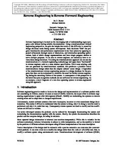
Figure 1 An example of a range image (a) obtained from the setup in Figure 5(a) for an automotive part (b). The coding in (a) indicates the distance (or range) from the camera
r = F(i; j; a ; b ; B; . . .);
(1)
where F is a function, possibly non-linear, i and j, respectively, represent the horizontal and vertical position of a pixel in the coordinates of the range image, a and b are the illumination and camera view angles, respectively, and B is the baseline distance between the camera and light source. These variables are the dominating parameters of a larger set that affects the range values. The type of light source determines the type of a structured light system. The three methods of illumination are single point, sheet-of-light, and coded light. Selection of an appropriate light source depends primarily on the scanning speed desired. The fastest and most ef® cient con® guration is the sheet-of-light system (Integrated Vision Products, 2000) where some sheet-of-light systems can scan approximately one million points per second. Comparing a similar number of scan points, the order of magnitude for a single point system is a few seconds, while the order for 224
Laser-based imaging for reverse engineering
Sensor Review
David Page, Andreas Koschan, Yiyong Sun and Mongi Abidi
Volume 23 · Number 3 · 2003 · 223–229
a coded light system is a few tens of seconds. With RE applications, these speeds translate in seconds, tens of seconds and minutes for a complete scanning of most objects. As the goal of a CARE system is to scan an object as fast as possible without disturbing the accuracy, the sheet-of-light scanners are an attractive design con® guration. Accuracy, itself, varies little among the systems, where one can expect millimeter to sub-millimeter accuracy. An example of a laser-sheet stripe is shown in Figure 2(b). With the sheet-of-light scanner, we must address a few problems. The ® rst one is the occlusion problem. Occlusions, as with most imaging systems, occur when surfaces of an object obstruct the full view of other surfaces
of the same object. Consider the hand crank shown in Figure 3(a). The wheel, spokes and hubs of the crank create an intricate structure such that the wheel or spokes obstruct views of surfaces for particular viewing angles. For a range imaging system, this problem means that we are unable to collect data points for the occluded surfaces if we only view the object from a single angle. To overcome this problem, we naturally take multiple views of an object such that we image each surface and hence, have a full coverage Figure 3(b). With multiple views, however, the scanning system becomes more complicated in that we now have more data to handle, and we must ensure that we properly cover the object. The fact that we have more data to handle is
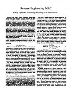
Figure 2 Structured light system. (a) Diagram for principles of operation. The laser illuminates point p and projects to pixel a. (b) A sheet-of-light example. The laser stripe across the objects projects to the image plane of the camera such that it illuminates only 1 pixel in each image column
Figure 3 The occlusion problem. (a) Hand crank example. (b) Multiple camera views avoid occlusions. View B is able to see the hashed line segment while the same segment is an occluded region for view A. In addition, the backsides of the object, which views A and B cannot see, are well within the views of C and D
225
Laser-based imaging for reverse engineering
Sensor Review
David Page, Andreas Koschan, Yiyong Sun and Mongi Abidi
Volume 23 · Number 3 · 2003 · 223–229
not necessarily a problem in itself, because most modern computer systems have vast amounts of data storage, but the problem is that each new view of an object leads to a new camera coordinate frame. So, the question is how do we align the local coordinate frames for each viewing angle into a single world coordinate frame. This problem is known as the registration problem, and we address it in a later section. A more immediate challenge is to ensure that we properly cover the entire surface of an object. This challenge is essentially a sensor placement problem, where solutions are known as next best view algorithms. The second problem that we must consider with a sheet-of-light scanner is error measurement. As with most data acquisition systems, measurement error is a problem that is always present. We de® ne such an error with the following equation x = p + e;
(2)
where x = (x; y; z) is the measured 3D point in camera frame coordinates, p is the actual point on the object surface and also in the camera frame coordinates, and e is the measurement error vector. Multiple sources of error arise in range systems from digital quantization of sensor signals to poor re¯ ective properties of surfaces. Because of the random nature of these errors, we group them into a single concept of noise error. Error characterization (Hashemi et al., 1994) and methods to overcome error (Page et al., 2001) are important research avenues. The ® nal problem that we must address is calibration. Calibration is the process of converting range values from an image-based coordinate system to a world-based coordinate system. We can de® ne calibration using the following equation: (x; y; z) = T (i; j; r);
(3)
where (x; y; z) are the world coordinates and (i; j; r) are the range image coordinates. The transformation T (: ) is the calibration of the image data into the world coordinates. With a given range scanner, we must develop a procedure to ® nd T (: ): The manufacturers of the range scanner that we use in this research de® ne a speci® c procedure for their scanner (Integrated Vision Products, 2000).
3. Model reconstruction After data acquisition, we have a set of range images representing multiple viewpoints around an object. The task now is to reconstruct a CAD model from these multiple range images. Model reconstruction is a multi-faceted problem that is perhaps one of the most dif® cult problems in computer vision and attracts more attention in the ® eld. A frequently cited paper that ® rst formalized the problem in the context of range imaging is by Hoppe et al. (1992) with another important work by Curless and Levoy (1996). The fundamental problems for reconstruction are: . aligning multiple views into a global coordinate frame, and . integrating and merging aligned views into a CAD representation.
3.1 Multiple view registration As discussed previously, multiple views of an object are necessary to overcome occlusions. As the camera moves to a new view, the resulting data is relative to the new view position. Registration is the process whereby we align these multiple views and their associated coordinate frames into a single global coordinate frame. The registration problem is essentially recovering the rigid transformation from the given raw range data. We de® ne the rigid transform as y = Rx + t;
(4)
where R represents a rotation matrix, t a translation vector, x the point in camera frame coordinates, and y the same point in world coordinates. Registration involves ® nding R and t. According to Horn et al. (1988), given three or more pairs of non-coplanar corresponding 3D points between two views, the unknown rigid transformation has a closed form solution. Thus, the registration problem becomes a point matching problem that establishes point pairs. The most popular algorithm for registration is the Iterative Closest Point (ICP) algorithm (Besl and McKay, 1992; Chen and Medioni, 1992). The ICP algorithm requires an initial estimate of the registration transformation and uses this estimate to establish closest point pairs. With these pairs, the algorithm estimates the new transformation that better aligns the data
226
Laser-based imaging for reverse engineering
Sensor Review
David Page, Andreas Koschan, Yiyong Sun and Mongi Abidi
Volume 23 · Number 3 · 2003 · 223–229
and iterates these steps until some threshold. A practical challenge with implementation of ICP is the need for an initial registration estimate. Through previous research, we have developed the Point Fingerprint Algorithm (Sun and Abidi, 2001). This algorithm computes geodesic circles around selected points on the surfaces for each view of the object. We then project these circles into the tangent plane of each point and thereby create a 2D image at that point, where this image is the geometric ª ® ngerprintº for that point. The algorithm matches two views according to their ® ngerprint images and from the resulting matches, it is able to roughly estimate the initial registration for the ICP algorithm to re® ne. 3.2 View integration Once we have multiple views registered, we then need to integrate these views into a single consistent surface representation. For this step, we can either consider the registered range data as a cloud of points (Hoppe et al., 1992) or as a set of surfaces (Turk and Levoy, 1994). The objective of view integration is to reconstruct the topology and surfaces of an object from the range samples. Although researchers are currently investigating a variety of algorithms, a promising class of methods is the volumetric techniques. These methods decompose the space around the data into a grid of volume elements (voxels). The earliest attempt for volumetric methods is a Delaunay approach proposed by Boissonnat (1984), and a very practical algorithm is the method of Curless and Levoy (1996) with the Digital Michelangelo Project (Levoy et al., 2000). We developed a volumetric reconstruction algorithm based on Hilton et al. (1998). A block diagram of this algorithm is shown in Figure 4. Using the data from each range view, the algorithm de® nes an implicit ® eld in the volume grid. From this ® eld, the algorithm computes a signed distance function and then extracts the ® nal representation using
a marching cubes algorithm (Lorensen and Cline, 1987). The complete details of our view integration algorithm are outlined by Sun et al. (2003).
4. Experimental results Based on the earlier research, we developed a CARE system within our laboratory. The objective of this system is to explore CARE technology in the context of automotive vehicle parts, where Figure 5 shows our test con® gurations. Figure 5(a) is the setup for under-vehicle scans while Figure 5(b) is a more controlled test bed that allows scanning of multiple views of a single object. This study has led to the generation of results shown in Figure 1 for the setup in Figure 5(a) and Figure 6 for the setup in Figure 5(b). The original objects are shown in Figure 6(a) and (b), while the associated reconstructed results are shown in Figure 6(c) and (d), respectively. The reconstruction accuracy for these results is of the order of 1-2 mm with the smoothing operations degrading the accuracy. To obtain these results, we used the MAPP 2500 Ranger System, which is a sheet-of-light system (Integrated Vision Products, 2000). The ranger consists of a special 512 £ 512 pixel camera and a low-power stripe laser. The ranger designers have speci® cally tailored the camera and its supporting electronics to integrate image processing functions onto a single parallel-architecture chip. This chip contained within the camera housing has a dedicated range processing function that allows for high-speed acquisition of nearly one million points per second. The most common arrangement of the system is to mount the camera and the laser source relative to the proposed target area to form a triangle where the camera, laser, and target are each corners of the triangle. The angle where the laser forms a corner is typically a right angle such that the laser
Figure 4 Block diagram of reconstruction algorithm for converting register range scans into integrated triangle mesh models
227
Laser-based imaging for reverse engineering
Sensor Review
David Page, Andreas Koschan, Yiyong Sun and Mongi Abidi
Volume 23 · Number 3 · 2003 · 223–229
Figure 5 Experimental setup for scanning automotive parts. (a) The laser-based imaging system is below the vehicle and the operator is seated behind the scanner and underneath the vehicle. (b) Controlled scanning setup where parts move below scanner on a conveyor belt
strip projects along one side of the triangle. The angle, a , at the camera corner is typically 30-608 . The baseline distance between the camera and the laser, denoted by B, completes the speci® cation of the triangle. Given B and a , the equation for range is as follows, and from equation (1) r(s) = B
f tana 2 s ; f + s tana
(5)
where f represents the focal length of the camera and s is the detected pixel row of the laser on the sensor (Integrated Vision Products, 2000). Finally, we added a band-pass optical ® lter (685 nm) to the camera lens so as to minimize the effects of spectral re¯ ections and inter-surface re¯ ections. After collecting the raw data using the ranger, the next step is reconstruction of the data into a CAD model. The objects shown in Figure 6 require multiple scans from
Figure 6 Reconstruction results for scans from a setup in Figure 5(b). (a) Hand crank. (b) Water neck. (c) Reconstructed 3D models of crank. (d) Reconstruction of water neck. These models and their raw range scans are available at http://iristown.engr.utk.edu/, page/database/
the described system. We used a brute force method to select each of the views with a trial-and-error approach. We register each of these scans using both an automatic (Sun and Abidi, 2001) and a manual algorithm. The computing platform for these algorithms is a SGI Octane with a single 195 MHz MIPS R10000 processor and 128 MB of memory. The manual algorithm was necessary when the automatic algorithm would fail. The ICP algorithm was used to re® ne the results for both the methods. Recall that equation (3) de® nes registration. Once the views are registered, then we reconstruct the triangle meshes with an integration algorithm (Sun et al., 2003). Finally, we smooth the models with a regularization technique similar to Sun et al. (2000).
5. Conclusions We have presented in this paper the results of a CARE system developed within our laboratory. This system focuses on many of the research challenges facing the reconstruction of automotive parts from range images. The discussion in previous sections highlighted these issues and noted speci® c areas of research that addresses them. For data
228
Laser-based imaging for reverse engineering
Sensor Review
David Page, Andreas Koschan, Yiyong Sun and Mongi Abidi
Volume 23 · Number 3 · 2003 · 223–229
acquisition, the primary areas of research are data calibration, occlusion problem, and error measurement. For reconstruction, the areas are view registration and view integration. We have addressed each of these issues using the IVP MAPP 2500 scanner and algorithms developed in our laboratory. The resulting system has led to the creation of a database of automotive parts as shown in Figure 6. These models are available online and are intended to serve the research community.
unorganized points”, Proc. of ACM SIGGRAPH, pp. 71-8. Horn, B., Hilden, H. and Negahdaripour, S. (1988), “Closed-form solution of absolute orientation using orthonormal matrices”, J. Optical Society of America A (Optics and Image Science), Vol. 5 No. 7, pp. 1127-35. Integrated Vision Products (2000), MAPP 2500 Ranger User Manual, Integrated Vision Products, Sweden. Levoy, M., Pulli, K., Curless, B., Rusinkiewicz, S., Koller, D., Pereira, L., Ginzton, M., Anderson, S., Davis, J., Ginsberg, J., Shade, J. and Fulk, D. (2000), “The digital Michelangelo Project: 3D scanning of large statues”, Proc. of ACM SIGGRAPH, pp. 131-44. Lorensen, W.E. and Cline, H.E. (1987), “Marching cubes: a high resolution 3D surface construction algorithm”, Proc. of ACM SIGGRAPH, pp. 163-9. Page, D.L., Koschan, A.F., Sun, Y., Paik, J.K. and Abidi, M.A. (2001), “Robust crease detection and curvature estimation of piecewise smooth surfaces from triangle mesh approximations using normal voting”, Proc. Int’l Conf. on Computer Vision and Pattern Recognition, Vol. 1, pp. 162-7. Sun, Y. and Abidi, M.A. (2001), “Surface matching by 3D point’s ngerprint”, Proc. IEEE Int’l Conf. on Computer Vision, Vol. 2, pp. 263-9. Sun, Y., Paik, J.K., Koschan, A.F. and Abidi, M.A. (2003), “Surface modeling using multi-view range and color images”, Integrated Computer-Aided Engineering, Vol. 10, pp. 37-50. Sun, Y., Paik, J.K., Price, J.R. and Abidi, M.A. (2000), “Dense range image smoothing using adaptive regularization”, Proc. IEEE Int’l Conf. on Image Processing, Vol. II, pp. 744-7. Thompson, W.B., Owen, J.C. and de St. Germain, H.J. (1999), “Feature-base reverse engineering of mechanical parts”, IEEE Trans. on Robotics and Automation, Vol. 15, pp. 57-66. Turk, G. and Levoy, M. (1994), “Zippered polygon meshes from range images”, Proc. of ACM SIGGRAPH, pp. 311-18. Va´rady, T. and Hermann, T. (1996), in Mullineux, G. (Ed.), The Mathematics of Surfaces VI, Oxford University Press, Oxford, pp. 411-27.
References Bernardini, F., Bajaj, C.L., Chen, J. and Schikore, D.R. (1999), “Automatic reconstruction of 3D CAD models from digital scans”, Int. J. Comp. Geometry and Applications, Vol. 9 Nos 4/5, pp. 327-69. Besl, P.J. (1989), “Active optical range imaging”, in Sanz, J.L.C. (Ed.), Advances in Machine Vision, Springer-Verlag, NY, pp. 1-53. Besl, P.J. and McKay, N.D. (1992), “A method for registration of 3D shapes”, IEEE Trans. Patt. Anal. Machine Intell., Vol. 14 No. 2, pp. 239-56. Boissonnat, J.D. (1984), “Geometric structures for three-dimensional shape representation”, ACM Trans. On Graphics, Vol. 3 No. 4, pp. 266-86. Chen, Y. and Medioni, G. (1992), “Object modeling by registration of multiple range images”, Image and Vision Computing, Vol. 10 No. 3, pp. 145-55. Curless, B. and Levoy, M. (1996), “A volumetric method for building complex models from range images”, Proc. of ACM SIGGRAPH, pp. 303-12. Hashemi, K.S., Hurst, P.T. and Oliver, J.N. (1994), “Sources of error in a laser rangender”, Review of Scientic Instruments, Vol. 65 No. 10, pp. 3165-71. Hilton, A., Stoddart, A., Illingworth, J. and Windeatt, T. (1998), “Implicit surface-based geometric fusion”, Computer Vision and Image Understanding, Vol. 69, pp. 273-91. Hoppe, H., DeRose, T., Duchamp, T., McDonald, J. and Suetzle, W. (1992), “Surface reconstruction from
229