LaLDPC: Latency-aware LDPC for Read Performance Improvement of Solid State Drives Yajuan Du∗† , Deqing Zou∗ , Qiao Li‡ , Liang Shi‡ , Hai Jin∗ , and Chun Jason Xue† ∗ Service
Computing Technology and System Lab, Cluster and Grid Computing Lab, Big Data Technology and System Lab, School of Computer Science and Technology, Huazhong University of Science and Technology, Wuhan, 430074, China Email:
[email protected],
[email protected],
[email protected] † Department of Computer Science, City University of Hong Kong, Kowloon, Hong Kong Email:
[email protected] ‡ College of Computer Science, Chongqing University, Chongqing, China Email:
[email protected],
[email protected] Abstract—High-density Solid State Drives (SSDs) have to use Low-Density Parity-Check (LDPC) codes to store data reliably. Current LDPC implementations apply multiple read-retry steps to find the appropriate set of multiple Reference Voltage (RVs) for successful decoding. These appropriate RVs, number of which is represented by read level, cannot be obtained in advance, instead, an iterative read-retry LDPC process happens that starts with the first read level with the smallest number of RVs and then increases the level until that the data have been successfully decoded. Only read-retry with the last read level, called the appropriate read level, is necessary. Read latency can be improved by avoiding read-retries. This becomes particularly important in the late stage of SSD life when high read levels are needed. To avoid unnecessary read-retries, this paper proposes Latency-aware LDPC (LaLDPC). We study read level characteristics along with data retention and observe that a single read level stays appropriate for a long time. During this time, all reads in the same page have probably the same appropriate read level, which we call the temporal read level locality. Using this value, LaLDPC estimates the starting read voltage level, which we store in the flash translation layer of the controller. As an example, we show how to integrate LaLDPC into the Demand-based Flash Translation Layer (DFTL). A new cache eviction algorithm is also proposed to leave entries with high read levels in the cache as long as possible. Experimental results show that LaLDPC saves 56% of read retries and improves SSD read performance by 18% on average compared with the existing LDPC method.
I. I NTRODUCTION Flash memory based Solid State Drives (SSDs) have been gradually replacing Hard Disk Drives (HDD) as the main storage medium in some applications, such as mobile phones and personal computers, with its characteristics of non-volatility, shock resistance, high speed, and low energy consumption [1]. In order to reduce the production cost, high-density flash memories have been developed, such as Multi-Level per Cell (MLC) flash [2], Triple-Level per Cell (TLC) flash [3] as well as 3D NAND flash [4], [5]. Although with larger storage space and lower price, these flash memories have worse endurance [6], [7]. One way to improve the endurance is to strengthen data reliability by Error Correction Codes (ECCs) [8], [9]. Corresponding author is Prof. Deqing Zou.
Traditional ECCs, such as BCH codes [10] cannot satisfy the reliability need of the exacerbated endurance problem in highdensity flash memory. Advanced codes, Low-Density ParityCheck (LDPC) codes [11]–[13], have been studied and implemented to provide higher error correction capability. However, LDPC codes often lead to long read latency, especially when SSDs are in the late stage of life [14]. This paper strives to improve read performance of flash-based SSDs that use LDPC codes. LDPC reads on flash memory involve three main processes: flash sensing, data transferring, and decoding. Flash sensing is first performed on flash cells. The sensed information is then transferred to flash controller and taken as the input of decoding. The long latency of LDPC reads comes from two aspects. On one hand, flash sensing is time-consuming because a set of multiple Reference Voltages (RVs) are applied [15], [16], the number of which is represented as a read level. As one sensing applies one RV, multiple sensing times with a fixed read level containing multiple RVs have to be performed to determine the threshold voltage states of flash cells. Furthermore, for high Raw Bit Error Rates (RBERs) caused by increased number of Program/Erase (P/E) cycles, a larger read level with more RVs, providing higher error correction capability, has to be applied to successfully decode older flash with LDPC codes [14], [17], [18]. This, of course, further increases the latency of flash sensing. From the latency specifications of MLC flash [15], flash sensing takes about 50µs with a low read level but more than 100µs with a high read level, which is much longer than the other two processes in LDPC reads. In a word, LDPC with a low read level is faster but can only correct errors in the early stages of flash life, whereas in the latter stages of life, a higher read level must be used at the cost of longer sensing latency. One read level, that happens to successfully decode the data and does not induce excessive sensing latency, is called the appropriate read level. On the other hand, in order to adapt error correction to the RBERs over the entire lifetime of flash, that require varied appropriate levels of RVs, current LDPC implementations
apply an iterative read-retry process, which starts with a low level of RVs and increases until the appropriate read level is found. This process accumulates read latencies of all readretries, which degrades read performance of SSDs with LDPC codes. If one could know the appropriate read level from the start, unnecessary read-retries can be avoided and SSD read performance would be largely optimized. This paper proposes Latency-aware LDPC (LaLDPC) to estimate an appropriate level of RVs. In a preliminary experiment, we observe that one read level can be appropriately used to read a page for a long time. During this time, all reads on this page have the same appropriate read level, which we call the temporal read level locality. LaLDPC implements two functions with marginal storage overhead. On one hand, LaLDPC applies the level of RVs used in the last read on one page as the start value of the read-retry iteration for the next reads on the same page. On the other hand, LaLDPC stores these read levels into Flash Translation Layer (FTL) and timely updates the level information once a higher read level happens. In this manner, unnecessary read-retries can be significantly reduced. As an example, we show how to integrate LaLDPC into the Demand-based Flash Translation Layer (DFTL) [19]. By noticing that pages with high read levels can achieve more performance benefits from LaLDPC, a new mapping cache eviction algorithm is proposed to leave these pages in the cache as long as possible, which can further strengthen the performance improvements of LaLDPC. In order to evaluate effectiveness of LaLDPC, we perform a series of experiments on the simulation platform, Disksim with SSD extensions [20], [21]. The read performance results of LaLDPC as well as the existing LDPC method have been collected from fifteen real workloads. The sensitivity of LaLDPC is studied on several parameters, such as cache size, and stages of flash life. Experimental results show that LaLDPC can improve read performance of the existing method. The main contributions of this paper are as follows: •
•
•
•
Analyzes the read-retry process of existing LDPC implementations and shows the severe problem of LDPC read latency accumulation, especially in the late stage of SSD life; Presents the observation on temporal read level locality that the appropriate RVs for reads on one page often last for a long time; Proposes a new LDPC method, LaLDPC, to estimate the appropriate RVs and significantly reduce unnecessary read-retries. LaLDPC is intergraded into DFTL with an improved cache eviction algorithm for further read performance improvement; Evaluates the proposed LDPC method with fifteen real workloads and shows that LaLDPC can reduce 56% of read-retries and improve SSD read performance by 18% on average compared with the existing LDPC method.
The remainder of this paper is organized as follows. Background and motivation are presented in Section II. The detailed design of LaLDPC is illustrated in Section III. Experiment
setup is presented in Section IV, and results and analysis are shown in Section V. Related work and conclusion of this paper are presented in Section VI and Section VII, respectively. II. BACKGROUND AND M OTIVATION This section first reviews the architecture of SSDs. Then, the read process with LDPC is analyzed. At last, the problem of read latency accumulation is studied. A. Basics of Solid State Drives Solid state drives consist of two main components: controller and NAND flash, as shown in Figure 1. The controller receives requests from host and decides how to organize data in flash. Several components are implemented in controller for better utilization of flash, such as FTL [22], [23], garbage collection, wear leveling, and LDPC encoder/decoder. FTL translates logical addresses requested by host into physical addresses with a mapping table. The mapping cache proposed in DFTL [19] keeps part of mapping entries with recently accessed pages while the whole mapping table is stored in translation blocks of flash. When the mapping cache runs out of space, one entry in the table has to be selected to evict and flush to translation blocks in NAND flash. Due to the out-of-place update characteristics of flash, data can not be directly overwritten but have to be programmed into other blocks. Garbage collection and wear leveling are responsible to reclaim blocks with invalid data and balance wears of blocks [24], [25]. LDPC encoder and decoder [26] ensure data reliability of flash. The raw data are first encoded into codewords and then stored in flash during write operations while codewords are decoded when they are read. Details of the encoder and decoder are presented in Section II-B.
Host Controller Mapping Cache (FTL)
Entry eviction
Garbage Collection
LDPC Encoder LDPC Decoder
Wear Leveling
Data blocks
Translation blocks
NAND Flash
Fig. 1. The architecture of solid state drives (SSDs). Several components are integrated into the controller for better utilization of flash.
B. Read Process with LDPC This section introduces the process of LDPC read: flash sensing, data transferring, and LDPC decoding. After FTL finds the physical addresses requested by host, flash sensing happens with multiple RVs. In this paper, the read level of LDPC is defined as the number of RVs between a pair of adjacent threshold voltage states of flash memory. An example of these RVs is shown in Figure 2, in which Vth in the xaxis represents threshold voltages while ]cells in the y-axis represents the number of cells. Based on threshold voltages in programming shown in Figure 2(a), the 3rd read level is applied with three RVs between two adjacent flash states, as shown in Figure 2(b). There are overall nine RVs applied in flash sensing. After flash sensing, the sensed data are transferred to controller by flash-to-controller bus. As the bus can only transfer a fixed amount of data for one time, the transfer latency is related to size of flash data. LDPC decoding happens after data are transferred to controller.
1 1 0 1 0 0 0 H =
Check nodes (rows of H)
0 0 1 1 1 0 0 0 0 0 1 0 1 1 Bit nodes (columns of H) LLR
Fig. 3. An example of parity-check matrix and tanner graph [29]. LLR information from flash sensing is taken as the input of tanner graph in bit nodes and a message passing algorithm is performed to find the codeword for successful decoding.
capability to correct errors is increased. The read-retry phase ends when LDPC decoding succeeds or the maximum read level is reached.
Initialization: i=1
T1
S1
T2
S2
Memory sensing (Si) Transfer (Ri) #cells
P1 10
P2 01
P3 00
Vth
Successful read
D1
+ R2
D2
+
LDPC decoding (Di) Fail Level increase (i = i + 1) until N
ER 11
R1
+ TL
SL
RL
DL
Fully Programmed Erased Partially Programmed (a) Threshold Voltage Distribution of MLC Flash #cells
Fig. 4. The read process and latency of existing LDPC [15]. The symbols Si , Ri and Di for read level i (1 ≤ i ≤ 7) represent the latency in each subprocess of LDPC read shown in the left part of this figure and Ti represents the overall flash read latency. Vth (b) Flash Sensing with Multiple Reference Voltages
Fig. 2. MLC flash sensing with different read levels. (a) MLC flash states with the RVs of the first read level. (b) Flash sensing with the 3rd read level, in which three RVs exist between each pair of adjacent flash states.
LDPC decoding has a large difference with traditional ECCs and involves a complex process. The sensed data are first transferred into log-likelihood ratio (LLR) information [27], [28], the input of LDPC decoder. The decoding iteratively passes messages through the tanner graph [29] generated from a parity-check matrix [30], as shown in Figure 3. Once a codeword is found, the decoding process finishes. The iteration counts are related to RBERs of data. As LDPC codes can be implemented by hardware, the decoding often takes small time cost. In current LDPC implementations, three stages can happen multiple times when LDPC decoding fails, as shown in the left part of Figure 4. For the read-retry in the ith read level with i ranging from 1 to the maximum iteration N, sensed data are transferred to LDPC decoder to perform the message passing decoding. When the decoding fails, i is incremented. With more reference voltages in a higher read level, the LDPC
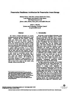
C. The Problem of Read Latency Accumulation This section analyzes the latency involved in each part of current LDPC implementation. The decoding process and latency details are presented in Figure 4. As the first step of LDPC read, flash sensing detects flash cell states with given RVs of the first read level. Then, the sensed data are transferred to flash controller by flash-to-controller bus. Subsequently, LDPC decoder performs the decoding algorithm on the data. The latencies of flash sensing, data transferring, and LDPC decoding with level i are denoted as Si , Ri , and Di , respectively. Thus, the read latency Ti with level i is computed as Ti = Si + Ri + Di . When decoding fails with the ith read level, the sensing with read level i + 1 is retried with incremented RVs. The read-retry process does not finish until the appropriate RVs are found. Assuming the read level with appropriate RVs on one flash page is L, overall PLread latency of current LDPC method [15] is computed as i=1 Ti , which is the accumulation of read latencies in all read-reties. From above analysis, if the appropriate RVs are known in advance, only the latency TL happens and the read performance is optimal. For the case with L > 1, latencies with read levels from 1 to L−1 are redundant. In order to investigate the read latency accumulation, quantitative analysis is performed
TABLE I BASIC LATENCIES IN FLASH READ WITH LDPC Steps in LDPC read The first level sensing Sensing one extra level Data transfer of the first level Data transfer of one extra level Decoding latency on average
Read latency 50µs 14µs 20µs 10µs 15µs
to show latency differences between the current LDPC and the optimal case with known RVs. According to the basic latencies listed in Table I [31], the latency results are shown in Figure 5(a). It can be found that there exists a large latency gap between current LDPC and the optimal case, especially for large read levels. The proposed technique in this paper aims to narrow this gap and solve the latency accumulation problem. Appropriate Read Level
Read Latency (µs)
1500 Current LDPC Optimal 1000
500
0
1
2
3 4 5 Read Level
6
7
(a) Read latency comparison
7
P/E=12000 P/E=10000
6
P/E=8000
5 4 3 2 1
100
200
300
400
500
Retention (day)
(b) Read level characteristics
Fig. 5. The illustration of read latency accumulation problem and read level characteristics. Temporal read level locality can be observed from the characteristics.
Based on above simulation method, appropriate read levels of LDPC codes along with retention for different P/E cycles, are shown in Figure 5(b). It can be found that read level changes with retention and keeps appropriate for a long time ranging from several days to several months. The step size of a read level jumping to the next level is related to P/E cycles. For all P/E cycles, the read level changes infrequently in the studied period. From this result, it can be concluded that one read level applied in the last read is probably appropriate for successive reads, which we call the temporal read level locality. By exploiting this characteristic, the proposed method, LaLDPC, takes the read level applied in the last read as the start read level of the next read. We present details of LaLDPC in the next section. III. L ATENCY- AWARE LDPC This section presents the design of our proposed Latencyaware LDPC (LaLDPC), as shown in Figure 6. One storage module and two functional modules are developed in LaLDPC: read level storage, mapping cache management, and LDPC assistant. The read level storage module stores the level information of each page while cache management module manages the value of read levels. The LDPC assistant module applies the information in read level storage module to assist LDPC decoding process. LaLDPC can be applied in all kinds of flash translation layers. This paper implements LaLDPC into DFTL as an example. In order to further strengthen the advantage of LaLDPC, a new mapping cache eviction algorithm is proposed and implemented in the cache management module.
D. Exploiting Temporal Read Level Locality
Flash Controller with LaLDPC Mapping cache (FTL) LPN
PPN
Level Bits
0
100
0001
1
210
0010
2
30
0001
Mapping Cache Management
LDPC Assistant LDPC Encoder/ Decoder
...
...
In the second step, appropriate read levels for RBERs computed in the first step are estimated from the result of decoding failure probability presented in [15]. For example, data with RBERs between 0.006 and 0.008 can be corrected by LDPC codes with the 3rd read level with a decoding failure probability smaller than 10−15 . Thus, the appropriate read level of RBERs in this range is 3. The correspondence between RBERs and the appropriate read levels is shown in Table II.
Host
...
In order to propose an accurate estimation of the appropriate read level, we investigate read level characteristics for different P/E cycles and retention time. The appropriate read level of one page with given P/E cycles and retention is obtained by two steps. In the first step, RBERs are computed according to the error model of Gaussian noises [32], described in Equation 1, considering random telegraph noises [33] and retention errors [8], [34]. In the model, N and t represent P/E cycle and retention time, respectively, while x and x0 represent the threshold voltage of the programmed states and that of the erased state, respectively. Other parameters are referenced from the settings in [32]: K0 = 0.333, K1 = 4 × 10⁻⁴ , K2 = 2 × 10−6 and x0 = 1.4. ( µ = K0 K1 (x − x0 )ln(1 + t/t0 )N 0.5 (1) σ 2 = K0 K2 (x − x0 )ln(1 + t/t0 )N 0.6
Entry eviction
Garbage Collection
Wear Leveling
Data blocks
Translation blocks
NAND Flash
Fig. 6. System architecture of LaLDPC. There are three components in LaLDPC: one storage component to store read levels in mapping cache and two functional components to manage read levels and assist LDPC decoding.
A. The Storage of Read Levels LaLDPC stores the last read levels applied in LDPC for all pages into the mapping cache entries in the controller. As one entry in the cache represents one page mapping, the read level is added into the end of each entry, as shown in Figure 6. For alignment consideration, four bits are used to represent
the level. In our implementation, the read level ranges from 1 to 7. In LaLDPC, the information of read levels is only stored in the mapping cache but not in translation blocks based on DFTL. There are several reasons for this design. First, for timeliness consideration on read requests, the levels used by recent reads has high reference value, and mapping cache keeps these recent reads. Second, as translation blocks store the mapping entries for all addresses, large storage overhead has to be paid on the read levels. Third, read levels have to be updated when read failure happens with lower read levels. If these updates happen in translation blocks, extra writes will be induced and impact read performance.
read level. When the maximum read level is reached, read failure is returned to the host; Step 4: Level difference detection module collects the read level from LDPC decoder and compares it with the stored read level to detect difference; Step 5: No read level difference is detected and read result is directly returned to the host; Step 6: Read level difference is detected and level bits of corresponding mapping entries are updated.
Memory sensing and transfer 2
B. Read Level Management and Utilization This section introduces the functional modules in LaLDPC, read level management and utilization. The mapping cache management module of LaLDPC, as shown in Figure 6, estimates the read level of each page by leveraging the read level of the last read to this page. There are four management scenarios to initialize and update the read levels. The first scenario is that when one entry is added to the mapping cache because of a first read, the read level is stored into level bits of the corresponding page as the initial read level. The second scenario is the update of read levels. When the new read level of the page is different from the stored read level, level bits are updated to the new one. The third scenario is that when one entry is added to the mapping cache because of a recent write, level bits of the corresponding page are initialized to be the first read level as data have not been kept. The fourth scenario involves page migration in garbage collection (GC) and wear leveling, the read levels of pages in new addresses are reset to be the first read level. We further introduce GC in Section III-D. The LDPC assistant module in LaLDPC assists the decoding process of LDPC decoder, as shown in Figure 6. It contains two sub-modules, read level determination and level difference detection, as shown in Figure 7. Read levels applied in LDPC decoder are determined and level difference detection assists the management of mapping cache in LaLDPC. As read level has to jump to the next level when LDPC decoding failure happens, the stored level bits should be updated to a newer one. The detailed read process with LaLDPC is listed as follows: Step 1: Read request to mapping entries enters read level determination module; Step 2: Read levels are determined to be different values in three cases. The first case is that when mapping cache hit happens, the starting level of read-retry steps in decoding is decided as the value of level bits. The second case is that when mapping cache miss happens, the starting level is set as the first read level. The third case is that when decoding failure happens in LDPC decoder, one extra level is added to perform memory sensing again; Step 3: LDPC decoding failure happens and be back to the read level determination module to obtain the next
Read request
1
Read level determination
Updated level
6
Level difference detection
Read result
5
4
LDPC Assistant
LLR generator 3
Iterative decoding Output buffer
LDPC Decoder
Fig. 7. Architecture of the LDPC assistant component and the process to perform LDPC decoding with the component.
C. Latency-aware Mapping Cache Eviction As traditional least recently used (LRU) cache eviction policy in DFTL can not be aware of the LDPC read latency of pages, this section presents a new cache eviction algorithm, as shown in Algorithm 1, to strengthen the performance advantage of LaLDPC. There are two considerations when choosing the item to evict in the proposed algorithm. From the analysis in Section II-C, the pages with high read levels induce more redundant read latency, which has larger space to be improved by LaLDPC. Thus, the first consideration prefers to evict pages with lower read levels, which ensures that highread-level pages can exist in the cache as long as possible. This method can improve the hit rate of pages with high read levels but may sacrifice the overall access locality. In order to reduce this side effect, the second consideration is to make quite recently accessed entries fixed and not be evicted. Then, the cache is partitioned into two parts: the part with fixed entries and the part with unfixed entries. In this way, a part of locality can be reserved. There are two possible cases in the proposed cache eviction algorithm, as shown in Figure 8. The first case is that there are entries that exist in the unfixed part and with the smallest read level of all stored levels. The last appearance of the entry of this kind is chosen to evict, which makes the choice by the first consideration suboptimal, as shown in Case 1 of Figure 8. The second case is that entries with the smallest read level all exist in the fixed part. Only entries in the unfixed part and with a larger read level can be chosen to evict. In this case, the algorithm chooses the last appeared entry with a read level as
Entry to evict Fixed entries Case 1:
2
2
1
2
1
2
1
3
1
2
Entry to evict Fixed entries Case 2:
3
2
2
1
3
2
Less recent
More recent
Fig. 8. Examples of two cases in the proposed cache eviction algorithm. The number in each box represents the stored read level in each mapping cache entry.
small level as possible, as shown in Case 2 of Figure 8. This case integrates the partial locality in the second consideration. The chosen entry is not optimal to be aware of read latency but can benefit cache hit ratio. In summary, the proposed algorithm searches the last cache entry with the lowest read levels within unfixed entries for eviction, as shown in Lines 6-12 of Algorithm 1. With the proposed algorithm, mapping cache can be aware of the LDPC latency of pages and keeps a part of locality in some degree, which ensures that the read levels can be utilized more efficiently in LDPC. D. Garbage Collection The connection between the proposed LaLDPC and garbage collection is two-fold. On one hand, LaLDPC can improve the performance of garbage collection by reducing read latency of valid pages in victim blocks. The valid pages in garbage collection are often cold data kept for long and have high error rates. Thus, valid pages often require high read latency. The situation can be relieved when the migrated pages hit the mapping cache in LaLDPC. Redundant read retries can be avoided and garbage collection performance can be improved. On the other hand, garbage collection changes the read levels of valid pages. As valid pages in victim blocks are decoded by LDPC in garbage collection, the error-free data can be obtained. Then, the read levels stored for these pages have to be reset to the initial read level when they are written to new blocks. Garbage collection decreases the read latency of future reads on valid pages. E. Analysis of Performance and Overhead This section analyzes read performance and overhead of LaLDPC with DFTL. Suppose the appropriate read level for current read is L1 and that applied in the last read and stored in mapping cache is L0 with L0 ≤ L1 . Read latency of the two reads are T1 and T0 , respectively. The cache hit rate is denoted as r. Read latency computed PL1 involved in LaLDPC PLis 1 as TLaLDP C = r · j=L T + (1 − r) · Tj while j 0 PL1 j=1 that of existing LDPC is TLDP C = j=1 Tj . Then, the latency difference between LaLDPC and the existing LDPC
Algorithm 1 Read Latency-aware Mapping Cache Eviction Algorithm INPUT: logical address requested LP N , initial mapping cache list InitM C, maximum length of mapping cache list LenM C , the length of fixed items in mapping cache Lenf ix , read level RLj of the jth cache item, the maximum read level Lmax ; OUTPUT: physical address requested P P N , updated cache list U pdatM C, the index of cache item to evict ind; 1: while SSD is running do 2: if request to LP N comes to mapping cache then 3: search LP N in initial cache list InitM C; 4: if LP N is not found and InitM C is full then 5: decide the item to evict and flush to flash; 6: for i = 0 to Lmax and j = LenM C to 1 do 7: if RLj ≤ i and j ≥ Lenf ix then 8: f ound = 1; 9: ind = j; 10: break; 11: end if 12: end for 13: remove the indth item of InitM C, insert LP N into InitM C by LRU rule and return U pdatM C; 14: else 15: directly insert LP N into InitM C by LRU rule and return U pdatM C; 16: end if 17: end if 18: end while
method is computed as Tdif f = TLDP C − TLaLDP C = PL1 PL1 PL0 r · ( j=1 Tj − j=L Tj ) = r · j=1 Tj . Read performance 0 benefits of LaLDPC are decided by two factors: the cache hit rate and the difference between the stored level L0 and the appropriate level L1 . For reads with higher cache hit rate and smaller difference, more redundant read-retries of LDPC can be reduced and read performance can be improved. Overhead of LaLDPC comes from the storage component and the functional components. The storage overhead in LaLDPC is taken by the read levels in mapping cache entries. Assuming the size of one mapping cache entry is 8 Bytes, the 4 portion of space taken by the four level bits is 8∗8 ∗ 100% = 6.25%. For mapping cache with the size of 256MB, level bits take 16MB storage space. As operations in controller are much faster than flash device, extra computational overhead caused by LaLDPC functional components can be ignored. IV. E XPERIMENT In order to evaluate effectiveness of the proposed technique, this paper simulates flash storage system using Disksim [21] with SSD extensions [20]. Experimental setup and parameters are presented in this section. The SSD system with the total size of 32GB is configured with eight packages, each of which has eight planes. Each plane contains 1024 blocks and each block has 64 pages. The page size is set to be 4KB. The
write latency for one page and block erase latency are set to be 900µs and 3.5ms for MLC flash, respectively [31]. Read latency for seven read levels in LDPC decoding are computed according to analysis in Section II-C and presented in Table II based on the latency of Table I. Statistics and performance results of fifteen real workloads from MSR [35], [36] and UMass [37] are collected. Specifications of the workloads including read/write ratio and duration time are listed in Table III. TABLE II R ELATIONSHIP BETWEEN RBER S AND THE APPROPRIATE READ LEVEL . read level 1 2 3 4 5 6 7
RBER < 0.005 [0.005, 0.006) [0.006, 0.008) [0.008, 0.009) [0.009, 0.01) [0.01, 0.012) [0.012, 0.013]
read latency (µs) 85 109 133 157 181 205 229
The performance results for four methods are collected, LDPC-in-SSD, Ideal, LaLDP CLRU , and LaLDP Cnew , the implementations of which are listed as follows. • • • •
LDPC-in-SSD is the current fine-grained progressive LDPC method [15]; Ideal assumes that the appropriate RVs are known in advance and directly applied for LDPC read; LaLDP CLRU is the proposed LaLDPC method implemented into DFTL with LRU cache eviction algorithm; LaLDP Cnew is the proposed LaLDPC method implemented into DFTL with the proposed cache eviction algorithm.
The evaluation contains two aspects: the basic experiment and sensitivity study. In the basic experiment, parameters are set as follows. The cache size in LaLDP CLRU and LaLDP Cnew is set to be 64MB. The fixed entry length of mapping cache in the eviction algorithm is set to be 2000. SSD is assumed to be in the middle stage of flash life with P/E cycle of 10000 and data retention of one year, which can reach RBERs that require LDPC read levels around 3 and 4 based on the model in Section II-D. In order to generate high RBERs that require LDPC soft sensing, the technique of programming speedup [38] is used to accelerate wears of flash cells. The programming step size is set to be 0.38V. In order to comprehensively investigate read performance of these methods, sensitivity study is performed on more settings of three parameters: mapping cache sizes, fixed entry lengths in the new cache eviction algorithm, and stages of SSD life. Besides the parameters in the basic experiment, the cache size is set to be two extra values of 32MB and 128MB. The fixed entry length is set to be 500 and 5000 as additional values. The SSD lifetime is set to be in two extra stages of early and late, with P/E cycles of 8000 and 12000 and the same retention as the basic experiment.
TABLE III S TATISTICS OF W ORKLOADS .
workload wdev0 rsrch2 proxy0 prn1 prn0 ts0 rsrch1 F1 F2 hm0 hm1 proj1 proj3 proj4 web1
reads 5172477 1090912 545985 6966661 19136490 3976632 1110 6508016 4312858 1167249 6444861 773087 3471062 1301436 7992543
writes 13153463 605720 4604603 18265525 5691238 14127647 334365 130648 100684 1932058 775983 5594270 65402 824502 1422974
read ratio 28% 64% 11% 28% 77% 22% 3% 98% 97% 37% 89% 12% 98% 61% 85%
days 6 6.6 0.5 1.3 0.7 4.7 5.7 0.5 0.5 0.4 4.8 0.1 0.6 3.9 7
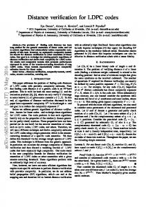
V. R ESULTS AND A NALYSIS This section presents experimental results for the four methods: LDPC-in-SSD, Ideal, LaLDP CLRU , and LaLDP Cnew . As different workloads have varied SSD read patterns and cache characteristics, which closely relate to the performance benefit of LaLDP CLRU and LDP Cnew , we first present statistical results of the fifteen workloads to provide references for performance results. Then, read performance results of the basic experiment are presented. The read performance metrics include flash read latency and SSD read response time. Flash read latency computes the overall latency taken by flash sensing, data transferring, and LDPC decoding. SSD read response time is the time from that the reads are issued in host to that read results are returned to the host. Then, results of system response time are presented to show the overall impact of LaLDP CLRU and LDP Cnew on SSD performance. System response time computes the average response time of both reads and writes. Lastly, results of sensitivity study are presented on the three parameters mentioned in Section IV. A. Statistics of Workloads This section presents three statistics of workloads. The first statistic is the distribution of the appropriate read levels, as shown in Table IV. We define hard read as the read with read level equal to one and soft read as that with read level larger than one. The difference between hard and soft reads is decided by the data retention patterns in workloads. As we assume one-year initial retention, data need soft reads at the beginning of workloads. When data are updated, read levels are reset to be one and become hard reads. This statistic reflects the potential performance improvement of workloads because only performance of soft reads can be improved. The second statistic is the ratio of soft-start reads, which indicates the LDPC reads that begin from soft read levels. Only with the assistant of LaLDP Cnew and LaLDP CLRU , LDPC read can start from soft read levels. The ratio of softstart reads reflects that how many reads in the workloads benefit from the two LaLDPC methods. From the result in
TABLE IV T HE SOFT READ RATIOS OF WORKLOADS .
workload wdev0 rsrch2 proxy0 prn1 prn0 ts0 rsrch1 F1
soft read ratio 36% 0.2% 17% 4% 22% 36% 91% 99%
workload F2 hm0 hm1 proj1 proj3 proj4 web1 -
soft read ratio 100% 41% 21% 0.5% 58% 5% 46% -
Normalized soft−start read number
Figure 9, LaLDP Cnew has higher soft-start read ratio than LaLDP CLRU , which indicates that the proposed new cache eviction algorithm in LaLDP Cnew can make more reads benefit from read-retry reduction, which we further explain in Section V-B. 7 6
LaLDPCnew
5
LaLDPCLRU
4 3 2 1 0 b1 ge ev0 ch2 xy0 rn1 rn0 tss0rch1 F1 F2hm0hm1proj1proj3proj4 wevera r wd rsr pro p p A
Fig. 9. The comparison of soft-start read number among all reads. The results are normalized to LaLDP CLRU .
The third statistic is the cache hit ratio of workloads, as shown in Figure 10. It can be observed that LaLDP Cnew shows decreased cache hit ratios than LaLDP CLRU . This is because that the new cache eviction algorithm in LaLDP Cnew keeps a part of access locality, which sacrifices the original locality in LRU cache eviction algorithm of LaLDP CLRU . However, the overall performance can be improved, which we further explain in Section V-C.
LaLDPC
Cache read hit ratio
1
new
LaLDPCLRU
0.8 0.6 0.4 0.2 0 b1 ge ev0 ch2 xy0 rn1 rn0 tss0rch1 F1 F2hm0hm1proj1proj3proj4 wevera r wd rsr pro p p A
Fig. 10. The comparison of cache read hit ratios between LaLDP CLRU and LaLDP Cnew .
B. Read Performance This section shows and analyzes read performance results of the four evaluated LDPC methods for the fifteen workloads.
The read performance is evaluated in two aspects, flash read latency and SSD read response time, and the results are shown in Figure 11. We first analyze the performance benefits brought by LaLDP Cnew and LaLDP CLRU compared with LDPCin-SSD and then present the comparison of read performance results with LaLDP Cnew and LaLDP CLRU . Read performance comparison between LDPC-in-SSD and the proposed LaLDPC methods. Read latency benefits from LaLDP Cnew and LaLDP CLRU , shown in Figure 11(a), are affected by two factors: the ratio of soft appropriate read levels and cache hit ratio, statistics of which are shown in Section V-A. The first factor decides how many latencies can be improved and decided by access patterns of workloads. For the workloads with high ratios, such as rsrch1, F 1, and F 2, there are a lot of redundant read latencies compared with the Ideal results, as shown in Figure 11(a). The read latency of LDPC-in-SSD is significantly improved by LaLDP Cnew and LaLDP CLRU for these workloads. On the contrary, for workloads with low ratios, such as rsrch2 and prn1, neither redundant read latencies nor latency improvements caused by LaLDP Cnew and LaLDP CLRU are obvious. This is because that only reads that require soft read levels have the problem of read latency accumulation. The two proposed methods can bring latency benefits on these reads. For the second factor to affect read latency, workloads with high hit ratios can benefit more improvements by the two LaLDPC methods. We analyze the workloads with similar ratios of soft read levels, such as wdev0, ts0, hm0, and web1. Among these workloads, web1 has the highest cache hit ratio as well as the most significant read latency improvement by LaLDP Cnew and LaLDP CLRU compared with LDPC-in-SSD. SSD read response time, as shown in Figure 11(b), is also effected by read ratios of workloads besides the two factors mentioned above. Among workloads with similar values in above two factors, such as wdev0, ts0, and hm0, workloads wdev0 and hm0 with higher read ratios achieve more read performance benefits from LaLDP Cnew and LaLDP CLRU compared with LDPC-in-SSD. Read performance comparison between LaLDP CLRU and LaLDP Cnew . Based on LaLDPC, the main difference between LaLDP CLRU and LaLDP Cnew exists in cache hit ratios because of different cache eviction algorithms. From the results in Figure 10 and Figure 11, it can be concluded that LaLDP Cnew leads to lower cache hit ratios but can improve flash read performance compared with LaLDP CLRU . However, for the workload F 2 with little writes, the read performance of LaLDP Cnew is no better than LaLDP CLRU . This may be because that LaLDP Cnew decreases the read locality, which affects performance improvement because of the special access pattern of this workload. This performance degradation can be relieved by keeping more fixed entries in mapping cache. In summary, the proposed two methods can achieve more performance benefits for workloads with higher read ratios, higher ratios of soft reads, and higher cache hit ratios. On average, LaLDP Cnew can remove 56% of redundant read
Flash read latency
1 0.8 0.6
LaLDPCnew
0.4
LaLDPCLRU
0.2
Ideal LDPC−in−SSD
0
y0 prn1 prn0 v0 h2 wde rsrc prox
ts0srch1 r
F1
F2 hm0 hm1 proj1 proj3 proj4 web1erage Av
Read response time
(a) Flash read latency comparison.
1 0.8 0.6
LaLDPCnew
0.4
LaLDPCLRU
0.2
Ideal LDPC−in−SSD
0
y0 prn1 prn0 v0 h2 wde rsrc prox
ts0srch1 r
F1
F2 hm0 hm1 proj1 proj3 proj4 web1erage Av
(b) Read response time comparison. Fig. 11. Read performance results of four methods normalized to LDPC-in-SSD.
C. System Response Time This section presents and analyzes the results of SSD response time, as shown in Figure 12. As read latency to flash affects on the latency of other parts in SSD, such as the request queuing time in controller and the write latency because of utilization of DFTL and the new cache eviction algorithm, the overall SSD response time may also be affected. From Figure 12, it can be observed that improvements of SSD system response time by LaLDP CLRU and LaLDP Cnew are similar with flash read performance but have small differences for some workloads, such as ts0 and hm1, which is decided by the access patterns of workloads. LaLDP Cnew shows improved system performance of these workloads than LaLDP CLRU . On average, about 24% of system response time in LDPCin-SSD can be improved. Above results verify that LaLDPC is effective on improving not only read performance but also system performance of SSDs. D. Sensitivity Study This section analyzes the sensitivity of read performance improvement by LaLDP Cnew on three parameters: mapping cache size, fixed entry length of mapping cache and stages of flash life. The experimental results are shown in Figure 13. From the results of different cache sizes, it can be found that when a larger mapping cache is used, more performance benefits of LaLDP Cnew and LaLDP CLRU can be achieved. This is because that read levels of more mapping entries can be stored in the larger cache, which brings higher cache hit rates for soft reads and more read latency reductions. From the
1 System response time
performance by comparing with the Ideal results and can improve read performance of LDPC-in-SSD by 18%.
0.8 0.6 0.4 0.2 0
LaLDPCnew LaLDPCLRU Ideal LDPC−in−SSD
v0 h2 y0 rn1 prn0 ts0 rch1 rs wde rsrc prox p
F1
F2 hm0 hm1 proj1 proj3 proj4 web1 rage Ave
Fig. 12. SSD system response time of four LDPC methods normalized to LDPC-in-SSD.
results of different fixed cache lengths, it can be found that when more entries are fixed in mapping cache, advantages of the new cache eviction algorithm LaLDP Cnew are decreased. This is because that with larger fixed entry length, long-latency reads stay in the mapping cache for a shorter time, which decreases benefits of LaLDP Cnew . However, the differences among three fixed entry lengths are not obvious, which means that read performance are not sensitive to this parameter. From the results of different stages of flash life, it can be found that for SSDs in the late life stage, high performance improvements can be achieved. This is because that when SSDs are in this stage, latency accumulation becomes more severe. And LaLDP Cnew and LaLDP CLRU have the capability to remove more redundant latencies. Compared with the other two parameters, LaLDPC is more sensitive to this parameter. Besides, there is a tradeoff between performance and overhead in LaLDPC methods. For example, larger cache size takes more space overhead although with better performance.
These parameters should be comprehensively considered in real SSDs.
0.8 0.6 0.4 0.2 0
LaLDPCnew LaLDPCLRU LDPC−in−SSD
32M 64M 128M
(a) Cache size.
1
0.8 0.6 0.4 0.2 0
LaLDPCnew LaLDPCLRU LDPC−in−SSD
500 2000 5000
(b) Fixed entry length.
Read Performance
1
Read Performance
Read Performance
1
0.8 0.6 0.4 0.2 0
LaLDPCnew LaLDPCLRU LDPC−in−SSD
ly mid late ear
(c) Flash lifetime.
Fig. 13. Read performance results of sensitivity study on three parameters normalized to LDPC-in-SSD.
VI. R ELATED W ORK Existing work to optimize read performance with LDPC in flash-based SSDs can be mainly categorized into three groups. The first group decreases the RBERs of data, as lower RBERs require less read latency. EC-Cache [39] proposes to store errors detected in last reads into an error correction cache. In the next read, these errors can be corrected before LDPC decoding. Li et al. [38] analyzed the cost models in flash reads and writes and proposed to obtain low RBERs of pages by applying fine-grained programming steps in writes. FlexLevel [40] optimizes read performance by strengthening error-tolerant capability of flash cells with less states. Only three states rather than traditional four states are used to store raw data in MLC flash, which can lower RBERs of flash pages. The refresh methods [41]–[43] are proposed to periodically correct data with long retention and reprogram them into new blocks, which can reduce retention-induced errors. The second group optimizes the flash sensing process by searching the appropriate RVs for decoding. LDPC-in-SSD [15] proposed to progressively apply fine-grained levels in LDPC reads. When the read with a lower level fails, the next level with several extra RVs is applied for flash sensing. This technique improves the read performance in the early stage of SSD life. In order to read out correct data with BCH codes, Cai et al. [34] proposed to record the optimal threshold voltages (OPTs) of the last programmed page in each block into the DRAM buffer of flash controller. The stored OPTs are applied on all page reads in the block, which largely reduces the response time for successful reads. Peleato et al. [44] presented a mathematical model based on the RVs in last read to adaptively estimate the appropriate RVs of current read. This paper belongs to this ground. Different from above works, the proposed LaLDPC method exploited the read level locality characteristics for LDPC read performance improvement. The third group optimizes LDPC decoding algorithm. Sun et al. [45] exploited intra-cell error characteristics to speed up LDPC decoding by reducing overall error probability and decoding latency. REAL [46] incorporates numeric-correlation characteristic of different error patterns in most significant bit and least significant bit of MLC flash into the message passing process of the decoding. LDPC decoder can achieve
successful decoding faster with the extra information provided by this characteristics. Aslam et al. [47] proposed a two-round LDPC decoding process by reusing the read-back voltages and the decoded results for flash cells from retention-induced failure, which can improve the decoding success probability and further read performance. In this paper, we did not change the design of LDPC decoder but optimized the communication mechanism between LDPC decoder and NAND flash with little overhead to improve read performance. VII. C ONCLUSION In order to solve the latency accumulation problem caused by existing LDPC methods, this paper proposes LaLDPC aiming at reducing redundant read-retries that cause latency accumulation. LaLDPC stores RVs in last read into FTL and apply them in future reads. LaLDPC has been implemented into DFTL as an example. In order to further strengthen the capability of LaLDPC, a new cache eviction algorithm is proposed. Experimental results show that the proposed method significantly improves read performance of SSDs compared with the existing LDPC method. ACKNOWLEDGEMENT The authors would like to thank Thomas Schwarz and all anonymous reviewers for their helpful feedbacks. This work is supported by National High-tech Research and Development Program of China (863 Program) under grant No.2015AA015303 and is partially supported by National Science Foundation of China under grant No. 61572411 and No. 61402059, and National 863 Program 2015AA015304. R EFERENCES [1] R. Bez, E. Camerlenghi, A. Modelli, and A. Visconti, “Introduction to flash memory,” Proceedings of the IEEE, vol. 91, no. 4, pp. 489–502, 2003. [2] Y. Cai, E. F. Haratsch, O. Mutlu, and K. Mai, “Threshold voltage distribution in MLC NAND flash memory: Characterization, analysis, and modeling,” in Design, Automation & Test in Europe Conference & Exhibition (DATE), 2013. IEEE, 2013, pp. 1285–1290. [3] S.-H. Shin, D.-K. Shim, J.-Y. Jeong, O.-S. Kwon, S.-Y. Yoon, M.-H. Choi, T.-Y. Kim, H.-W. Park, H.-J. Yoon, Y.-S. Song, C. Yoon-Hee, S.-W. Shim, Y.-L. Ahn, K.-T. Park, J.-M. Han, K. Kye-Hyun, and J. Young-Hyun, “A new 3-bit programming algorithm using SLC-to-TLC migration for 8MB/s high performance TLC NAND flash memory,” in Symposium on VLSI Circuits (VLSIC). IEEE, 2012, pp. 132–133. [4] H.-T. Lue, T.-H. Hsu, Y.-H. Hsiao, S. Hong, M. Wu, F. Hsu, N. Lien, S.-Y. Wang, J.-Y. Hsieh, L.-W. Yang, T. Yang, K. C. Chen, K.-Y. Hsieh, and C.-Y. Lu, “A highly scalable 8-layer 3D vertical-gate (VG) TFT NAND flash using junction-free buried channel BE-SONOS device,” in Symposium on VLSI Technology (VLSIT). IEEE, 2010, pp. 131–132. [5] H. Tanaka, M. Kido, K. Yahashi, M. Oomura, R. Katsumata, M. Kito, Y. Fukuzumi, M. Sato, Y. Nagata, Y. Matsuoka et al., “Bit cost scalable technology with punch and plug process for ultra high density flash memory,” in Symposium on VLSI Technology. IEEE, 2007, pp. 14–15. [6] P. Huang, G. Wu, X. He, and W. Xiao, “An aggressive worn-out flash block management scheme to alleviate SSD performance degradation,” in Proceedings of the Ninth European Conference on Computer Systems (EuroSys). ACM, 2014, p. 22. [7] K. Zhou, S. Hu, P. Huang, and Y. Zhao, “LX-SSD: Enhancing the lifespan of NAND flash-based memory via recycling invalid pages,” in International Conferenceon Massive Storage Systems and Technology (MSST). IEEE, 2017.
[8] Y. Cai, E. F. Haratsch, O. Mutlu, and K. Mai, “Error patterns in MLC NAND flash memory: measurement, characterization, and analysis,” in Design, Automation & Test in Europe Conference & Exhibition (DATE). IEEE, 2012, pp. 521–526. [9] P. Huang, P. Subedi, X. He, S. He, and K. Zhou, “FlexECC: Partially relaxing ECC of MLC SSD for better cache performance.” in USENIX Annual Technical Conference, 2014, pp. 489–500. [10] G. D. Forney, “On decoding BCH codes,” Information Theory, IEEE Transactions on, vol. 11, no. 4, pp. 549–557, 1965. [11] D. J. MacKay, “Good error-correcting codes based on very sparse matrices,” Information Theory, IEEE Transactions on, vol. 45, no. 2, pp. 399–431, 1999. [12] J. Thorpe, “Low-density parity-check (LDPC) codes constructed from protographs,” IPN progress report, vol. 42, no. 154, pp. 42–154, 2003. [13] S. Myung, K. Yang, and J. Kim, “Quasi-cyclic LDPC codes for fast encoding,” Information Theory, IEEE Transactions on, vol. 51, no. 8, pp. 2894–2901, 2005. [14] “Samsung 750 EVO SSD review 2016,” http://www.tomshardware.com/reviews/samsung-750-evossd,4467.html, accessed: 2016-11. [15] K. Zhao, W. Zhao, H. Sun, X. Zhang, N. Zheng, and T. Zhang, “LDPCin-SSD: making advanced error correction codes work effectively in solid state drives,” in Presented as part of the 11th USENIX Conference on File and Storage Technologies (FAST), 2013, pp. 243–256. [16] Q. Li, L. Shi, C. J. Xue, Q. Zhuge, and E. H.-M. Sha, “Improving LDPC performance via asymmetric sensing level placement on flash memory,” in Asia and South Pacific Design Automation Conference (ASP-DAC). IEEE, 2017, pp. 560–565. [17] L. Shi, K. Wu, M. Zhao, C. J. Xue, and H. Edwin, “Retention trimming for wear reduction of flash memory storage systems,” in Design Automation Conference (DAC). IEEE, 2014, pp. 1–6. [18] Y. Di, L. Shi, K. Wu, and C. J. Xue, “Exploiting process variation for retention induced refresh minimization on flash memory,” in Design, Automation & Test in Europe Conference & Exhibition (DATE). IEEE, 2016, pp. 391–396. [19] A. Gupta, Y. Kim, and B. Urgaonkar, “DFTL: a flash translation layer employing demand-based selective caching of page-level address mappings,” in ASPLOS, 2009. [20] N. Agrawal, V. Prabhakaran, T. Wobber, J. D. Davis, M. S. Manasse, and R. Panigrahy, “Design tradeoffs for SSD performance.” in USENIX Annual Technical Conference, 2008, pp. 57–70. [21] “The disksim simulation environment (v4.0),” http://www.pdl.cmu.edu/DiskSim/, accessed: 2016-11. [22] Y. Zhou, F. Wu, P. Huang, X. He, C. Xie, and J. Zhou, “An efficient page-level FTL to optimize address translation in flash memory,” in Proceedings of the Tenth European Conference on Computer Systems (EuroSys). ACM, 2015, p. 12. [23] J. Kim, J. M. Kim, S. H. Noh, S. L. Min, and Y. Cho, “A spaceefficient flash translation layer for CompactFlash systems,” Consumer Electronics, IEEE Transactions on, vol. 48, no. 2, pp. 366–375, 2002. [24] M. Murugan and D. H. Du, “Rejuvenator: A static wear leveling algorithm for NAND flash memory with minimized overhead,” in Symposium on Mass Storage Systems and Technologies (MSST). IEEE, 2011, pp. 1–12. [25] C.-W. Tsao, Y.-H. Chang, and M.-C. Yang, “Performance enhancement of garbage collection for flash storage devices: an efficient victim block selection design,” in Proceedings of the 50th Annual Design Automation Conference. ACM, 2013, p. 165. [26] K. Gunnam, “LDPC decoding: VLSI architectures and implementations,” Invited presentation at Flash Memory Summit, Santa Clara [Online]. Available: http://sites.ieee.org/scv-pace/files/2014/08/FMS14LDPC-Module2.pdf., 2013. [27] J. Wang, T. Courtade, H. Shankar, and R. D. Wesel, “Soft information for LDPC decoding in flash: Mutual-information optimized quantization,” in Global Telecommunications Conference (GLOBECOM). IEEE, 2011, pp. 1–6. [28] G. Dong, N. Xie, and T. Zhang, “On the use of soft-decision errorcorrection codes in NAND flash memory,” Circuits and Systems I: Regular Papers, IEEE Transactions on, vol. 58, no. 2, pp. 429–439, 2011. [29] X.-Y. Hu, E. Eleftheriou, and D.-M. Arnold, “Regular and irregular progressive edge-growth tanner graphs,” Information Theory, IEEE Transactions on, vol. 51, no. 1, pp. 386–398, 2005.
[30] R. Smarandache and P. O. Vontobel, “Quasi-Cyclic LDPC codes: Influence of proto-and tanner-graph structure on minimum hamming distance upper bounds,” Information Theory, IEEE Transactions on, vol. 58, no. 2, pp. 585–607, 2012. [31] “Open NAND flash specification,” http://www.onfi.org/specifications, accessed: 2016-11. [32] Y. Pan, G. Dong, Q. Wu, and T. Zhang, “Quasi-nonvolatile SSD: Trading flash memory nonvolatility to improve storage system performance for enterprise applications,” in International Symposium on High Performance Computer Architecture (HPCA). IEEE, 2012, pp. 1–10. [33] M. Luo, R. Wang, S. Guo, J. Wang, J. Zou, and R. Huang, “Impacts of random telegraph noise (RTN) on digital circuits,” Electron Devices, IEEE Transactions on, vol. 62, no. 6, pp. 1725–1732, 2015. [34] Y. Cai, Y. Luo, E. F. Haratsch, K. Mai, and O. Mutlu, “Data retention in MLC NAND flash memory: Characterization, optimization, and recovery,” in International Symposium on High Performance Computer Architecture (HPCA). IEEE, 2015, pp. 551–563. [35] “MSR cambridge traces,” http://iotta.snia.org/tracetypes/3, accessed: 2016-11. [36] D. Narayanan, A. Donnelly, and A. I. T. Rowstron, “Write off-loading: Practical power management for enterprise storage,” in FAST, 2008. [37] “UMass trace repository,” http://traces.cs.umass.edu/index.php/Storage/Storage, accessed: 2016-11. [38] Q. Li, L. Shi, C. J. Xue, K. Wu, C. Ji, Q. Zhuge, and E. H.-M. Sha, “Access characteristic guided read and write cost regulation for performance improvement on flash memory,” in USENIX Conference on File and Storage Technologies (FAST). USENIX, 2016, pp. 125–132. [39] R.-S. Liu, M.-Y. Chuang, C.-L. Yang, C.-H. Li, K.-C. Ho, and H.-P. Li, “EC-cache: Exploiting error locality to optimize LDPC in NAND flashbased ssds,” in Design Automation Conference (DAC). ACM, 2014, pp. 1–6. [40] J. Guo, W. Wen, J. Hu, D. Wang, H. Li, and Y. Chen, “Flexlevel: a novel NAND flash storage system design for LDPC latency reduction,” in Design Automation Conference (DAC). ACM, 2015, p. 194. [41] Y. Cai, G. Yalcin, O. Mutlu, E. F. Haratsch, A. Cristal, O. S. Unsal, and K. Mai, “Flash correct-and-refresh: Retention-aware error management for increased flash memory lifetime,” in International Conference on Computer Design (ICCD). IEEE, 2012, pp. 94–101. [42] Y. Luo, Y. Cai, S. Ghose, J. Choi, and O. Mutlu, “WARM: Improving NAND flash memory lifetime with write-hotness aware retention management,” in Symposium on Massive Storage Systems and Technologies (MSST). IEEE, 2015, pp. 1–14. [43] Q. Li, L. Shi, C. Gao, K. Wu, C. J. Xue, Q. Zhuge, and E. H.-M. Sha, “Maximizing IO performance via conflict reduction for flash memory storage systems,” in Design, Automation & Test in Europe Conference & Exhibition (DATE). IEEE, 2015, pp. 904–907. [44] B. Peleato, R. Agarwal, J. M. Cioffi, M. Qin, and P. H. Siegel, “Adaptive read thresholds for NAND flash,” Communications, IEEE Transactions on, vol. 63, no. 9, pp. 3069–3081, 2015. [45] H. Sun, W. Zhao, M. Lv, G. Dong, N. Zheng, and T. Zhang, “Exploiting intracell bit-error characteristics to improve min-sum LDPC decoding for MLC NAND flash-based storage in mobile device,” VLSI System, IEEE Transactions, vol. 24, pp. 2654–2664, 2016. [46] M. Zhang, F. Wu, X. He, P. Huang, S. Wang, and C. Xie, “REAL: A retention error aware LDPC decoding scheme to improve NAND flash read performance,” in Symposium on Mass Storage Systems and Technologies (MSST). IEEE, 2016. [47] C. Aslam, Y. Guan, and K. Cai, “Retention-aware belief-propagation decoding for NAND flash memory,” Circuits and Systems II: Express Briefs, IEEE Transactions on, 2016.