International Journal of
Applied Mathematics, Electronics and Computers ISSN: 2147-82282147-6799
Advanced Technology and Science
http://ijamec.atscience.org
Original Research Paper
Learning Based Experimental Approach For Condition Monitoring Using Laser Cameras In Railway Tracks Yunus Santur 1, Mehmet Karaköse *2, Erhan Akın 3 Accepted 3rd September 2016
DOI: 10.18100/ijamec.xxxxx
Abstract: Detecting the rail surface faults is one of the most important components of railway inspection process which should be performed periodically. Today, the railway inspection process is commonly performed using computer vision. Performing railway inspection based on image processing can lead to false-positive results. The fact that the oil and dust residues occurring on railway surfaces can be detected as an error by the image processing software can lead to loss of time and additional costs in the railway maintenance process. In this study, a hardware and software architecture are presented to perform railway surface inspection using 3D laser cameras. The use of 3D laser cameras in railway inspection process provides high accuracy rates in real time. The reading rate of laser cameras to read up to 25.000 profiles per second is another important advantage provided in real time railway inspection. Consequently, a computer vision-based approach in which 3D laser cameras that could allow for contactless and fast detection of the railway surface and lateral defects such as fracture, scouring and wear with high accuracy are used in the railway inspection process was proposed in the study. Keywords: Railway Inspection, Anomaly Detect, Computer Vision, Laser Camera, Machine Learning
1. Introduction In industrial applications, it is necessary to conduct activities such as maintenance, condition monitoring and fault detection as well as production. In recent years, these operations are commonly conducted using computer vision [1]. Computer vision ensures that these operations are conducted fast with high accuracy and without human dependence. Due to all these advantages offered by it, the maintenance, monitoring and fault detection conducted using computer vision are also commonly used in railway rail inspection as in other fields of the industry [2]. Rail transportation systems are widely used all around the world. The anomalies that could occur or are present on railway can lead to both troubles and financial losses and accidents in the transportation system. Therefore, the rail line should be checked periodically [3]. Today, the rail inspection operation is basically divided into two groups as contact and contactless methods. The simplest method of inspecting is that an expert visually inspects the rail line with mechanical measuring instruments. This method is limited by very slow, low accuracy specialized knowledge inspecting the rail line [4]. Another one of the contact methods is performing the rail inspection with ultrasonic devices. Fault detection is conducted by analyzing the data and graphics obtained by the friction of the mechanical device which is moved along the rail line to the railway rail line [4]. These inspection process is slow and provides low accuracy. Its most important disadvantage is that the mechanical device can _______________________________________________________________________________________________________________________________________________________________
Computer Engineering Department, Engineering Faculty, Fırat University, Campus, 23100, Elazığ/Turkey * Corresponding Author: Email:
[email protected] Note: This paper has been presented at the 3rd International Conference on Advanced Technology & Sciences (ICAT'16) held in Konya (Turkey), September 01-03, 2016. 1,2,3
This journal is © Advanced Technology & Science 2013
increase the existing fault on the rail line or new faults may occur because of the device's necessity of friction to the rail line during inspection. Another one of the contact methods is performing the rail inspection with ultrasonic devices. Fault detection is conducted by analyzing the data and graphics obtained by the friction of the mechanical device which is moved along the rail line to the railway rail line [4]. Its most important disadvantage is that the mechanical device can increase the existing fault on the rail line or new faults may occur because of the device's necessity of friction to the rail line during inspection. Although contact methods are low-cost, they have significant disadvantages because they do not have high accuracy ratios and
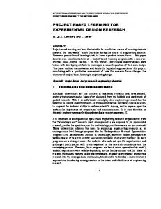
Figure 1. Rail inspection with 3D laser camera
the inspection process is long. Today, rail inspection operation can be performed rapidly as contactless and with high accuracy using computer vision. The long rail lines can be inspected real-timely in the contactless rail inspection operation that uses the computer vision. The inspection operation consists of the steps of determining the components of the rail line and the deficiency (such as missing traverse and bolt) or anomaly conditions in these components [713]. The rail inspection applications in which light source and high resolution cameras are used may lead to the generation of false IJAMEC, 2016, 4 (Special Issue ICAT’16), 1–5 | 1
positive results by detecting the stains formed by oil and dust particles on the rail line as anomaly in addition to high accuracy ratios and real-time operating speeds [8]. When three-dimensional laser cameras are compared with normal cameras, they involve both rgb data and precise distance information on the two-dimensional plane. Because of these features, they are widely used with the aim of finding faults in industrial products including rail inspection [9-12]. Although the cost rail inspection with 3-d cameras is higher, it is the most advantageous method in terms of accuracy rate and operating speed. The general components of a 3D computer vision-based rail inspection operation are seen in Fig. 1. The rail inspection methods are comparatively presented with their specific advantages and disadvantages in Table I [4].
Non-Contacted Meth.
Contacted Methods
Table 1: Rail inspection methods
Advantages Cheap
Fast
Comput er vision
Safe Fast High accuary
Comput er vision with 3dlaser camera
Safe Very fast Very high accuary
Methods Mechani c devices Ultrason ic devices
Disadvantages Very slow Unsafe Low accuary Slow Increase existing damage Expensive False positive results
the z plane. The methods of stereovision, time of flight and laser triangulation are used in obtaining three-dimensional image [14]. Stereo vision technique is the same as the principle of human vision. It is based on the principle of finding the pixel distance by measuring the projections of each pixel on two separate cameras by geometric methods because the distance and angle between cameras are known in imaging which is performed using two separate calibrated cameras. Although it is low cost, the accuracy performances depend on calibration and the sensitivity of camera parameters [15]. Time of flight cameras containing both rgb camera and an infrared sensor get depth information as well as rgb information by measuring the flight time of the infrared waves. They are particularly used in applications such as game consoles, virtual reality and three-dimensional modeling. They have cost effective and low accuracy solutions [14, 15]. Another method used in obtaining three-dimensional image is the use of laser cameras [16]. Laser cameras consist of a calibrated camera and laser line source as shown in Fig. 2. These components are usually integrated products. The system builds up the three-dimensional profile of the object by benefiting from the profile change in the laser line via constantly taking pictures. The object needs to move in a controlled manner while performing the profiling process in moving objects with laser cameras. How much the object has moved is determined by means of an encoder.
Expensive
A typical rail inspection application running based on computer vision includes the following steps respectively [7]. Preprocessing: It includes the steps of preprocessing the camera data that constitute the input of the system for noise removal and similar purposes. Dimension Reduction: It includes the processes of obtaining eigenvalue from large-scale camera data by feature extraction methods to operate real-timely. Learning: It includes the step of training the data obtained in the previous step by machine learning algorithms. Test: It includes the step of classifying the new data according to values learned by the system during training and generating diagnostic results during test or real-time inspection. Other: It includes the operations such as the evaluation of other sensor data such as accelerometer, gyroscop and encoder to be used in the system, and recording all data for system confusion matrix extraction. A study that includes the steps of calibrating the cameras, extracting three-dimensional rail profiles by taking data from cameras, obtaining eigenvalue on these profiles by feature extraction methods, and training and testing of the system by machine learning for a rail inspection application in which 2 3D laser cameras are used for the left and right surfaces of the rail line is presented in this paper.
a)
AT C5 laser camera
b)
3D measurement of rail
Figure 2. Getting 3D data from AT C5-1600CS laser camera
The simple mathematical provision of the process of obtaining three-dimensional profile matrix by reading the rail profile can be given as in (1,2) from calibrated compact sensor as shown in Fig. 3. The typical features of 3D laser cameras by taking the AT C51600CS19-500 presented in the study as a reference are presented in Table II [17]. 𝑧=
𝑥
(1)
sin(𝑎)
PTreshold =
PL +PR
(2)
2
2. 3D Laser Cameras And Getting 3D Data The standard cameras operating with sensors such as Ccd and Cmos give two-dimensional image on x-y plane. This image is called as three-dimensional if it includes the depth information on 2 | IJAMEC, 2016, 4 (Special Issue ICAT’16), 1–5
a)
Laser triangulation
b)
Laser beam
This journal is © Advanced Technology & Science 2013
Figure 3. Laser triangulation Table 2. AT C51600CS19-500 laser camera features [17] Feature Value Performance 25.000 Profile/Second Resolution 1600 x 1088 Field of View 500 mm 3d resolutions (lateralxheight) 313x15 m Interface Gigabit ethernet 3D profile matrix size 1600x3 Other High-pass filter, vivration reduction
3. Proposed Method The test device and the block diagram of the proposed method conducted for the system are given in Fig. 4. The proposed approach works in two stages. In the learning stage, rail profiles that taken from laser camera are used with “healty” and “faulty” tags. First two attributes from every method of dimension reduction (Principal Component Analysis) are used in learning algorithms [18-19]. The data of these two classes are educated in compliance with the Random Forest (RF) machine learning algorithm and a decision forest is created. RF method works fast and with high accuracy on big data and that is the main reason this method was selected. Thus, the learned model build in the training stage. In test stage, a rail which contains faulty and healthy profiles not used in the training stage. In test stage, attributes from read profiles from this railway is acquired again and the results are compared in the decision forest, the closest class is detected and a decision was made on whether there is a fault on the frame.
b) Experimental tool Figure 4. Experimental tool and proposed method
4. Experimental Results In rail inspection operations conducted using three-dimensional laser cameras, the experimental results include the steps of calibrating the laser cameras and obtaining rail profiles by preprocessing the three-dimensional data obtained from the calibrated cameras. The obtained three-dimensional rail profiles will constitute the input data of the machine learning-based fault diagnosis algorithm. In the next step, the eigenvalue was obtained on the rail profiles by feature extraction methods, and it was labeled as faulty and healthy to be used in training algorithm. The system was trained by using Random Forest (RF) which is a classification method using multiple decision trees [20]. It is one of the most suitable classification algorithms to be used in fault diagnosis since it functions rapidly even in large data sets, provides good results on lost data and generates high accuracy results.
a)
a)
Block diagram of the proposed method
This journal is © Advanced Technology & Science 2013
Rail line which is used in experimental studies
b)
3d rail profiles of rail lines
IJAMEC, 2016, 4 (Special Issue ICAT’16), 1–5 | 3
In general, there are three criteria expected from a rail inspection application. These are the high accuracy results, high operating speed and the cost of the system. 3D laser cameras allow for obtaining higher accuracy rate in rail inspection because they include both Rgb data and precise distance information that two-dimensional cameras have. When they are compared with normal cameras, their another advantage is that they are more susceptible to false positive result situations in oil and dust stains caused by image processing algorithms because they use distance information. The second criterion expected in rail inspection applications is the high operating speed. Today, laser cameras are suitable for real-time operation on a real transportation device by their profile generation speed of 25.000 per second. The third success criterion expected in rail inspection applications is the cost of the system. High speed and accuracy rates can be obtained in applications using 3D laser cameras, but their costs are higher. It is thought that this disadvantage is eliminated by their other advantages. c)
crack rail line
d)
3d profile crack rail
Acknowledgements This work was supported by the TUBITAK (The Scientific and Technological Research Council of Turkey) under Grant No: 114E202.
References Y. Tai-shan, C. & Du-wu. The method of intelligent inspection of product quality based on computer vision, In 2006 7th International Conference on Computer-Aided Industrial Design and Conceptual Design , pp. 1-6, IEEE, 2006. [2] S. Zheng, X. Chai, X. An, L. Li. Railway track gauge inspection method based on computer vision, In 2012 IEEE International Conference on Mechatronics and Automation, pp.1292-1296, IEEE, 2012. [3] Q. Li, Z. Zhong, Z. Liang, Y. Liang. Rail Inspection Meets Big Data: Methods and Trends, In Network-Based Information Systems (NBiS), 2015 18th International Conference, pp.302-308, IEEE, 2015. [4] D. F. Cannon, K. O. EDEL, S. L. Grassie, K. Sawley. Rail defects: an overview, Fatigue & Fracture of Engineering Materials & Structures, 26(10), 865-886, 2003. [5] www.cater-eu.com/gallery, “C.A.T.E.R”. [Online]. 2016 [6] Y. Santur, M. Karaköse, İ. Aydın and E. Akın. IMU based adaptive blur removal approach using image processing for railway inspection, In 2016 International Conference on Systems, Signals and Image Processing (IWSSIP), pp.1-4, IEEE, May, 2016. [7] E. Resendiz, L. F. Molina, J. M. Hart, J. R. Edwards, S. Sawadisavi, N. Ahuja and C. P. L. Barkan. Development of a machine-vision system for inspection of railway track components, In 12th World Conference on Transport Research, 12.WCTR, Lisbon, Portugal, 2010. [8] R. Huber-Mörk, M. Nölle, A. Oberhauser, E. Fischmeister. Statistical Rail Surface Classification Based on 2D and 21/2D Image Analysis, In Advanced Concepts for Intelligent Vision Systems, pp.50-61, 2010 [9] T. Hackel, D. Stein, I. Maindorfer, M. Lauer and A. Reiterer. Track detection in 3-D laser scanning data of railway infrastructure, I2MTC, 2015 IEEE International (pp. 693-698), 2015. [10] İ. Aydın, E. Karaköse, M. Karaköse, M.T. Gencoglu and E. Akın. A New Computer Vision Approach for Active Pantograph Control, IEEEInternational Symposium on [1]
e)
wear rail line
f)
3d profile wear rail line
Figure 5. Experimental resutls
The trained system was tested by measuring the operating speed and accuracy performance on a rail line for a short time in the test phase. A total of 400 rail profiles were collected on a short rail line by the proposed system, and these profiles were trained by labeling as healthy and faulty. 75% of the dataset was used in training. The remaining 25% was used for testing purposes. % 98 accuracy rate was achieved in the test phase. The receiver operating characteristic (ROC) analysis was used to obtain the accuracy performance values shown in detecting the "faulty" frames containing system anomalies and the "healthy" frames having no anomalies [18].
5. Conclusion Rail transportation systems are widely used around the world. The rail lines should be inspected periodically and their maintenance should also be performed to ensure the railway transportation safety. Today, this inspection process is commonly carried out using CVS. In this study, the software architecture is presented for a rail inspection conducted using 3D laser cameras. 4 | IJAMEC, 2016, 4 (Special Issue ICAT’16), 1–5
This journal is © Advanced Technology & Science 2013
[11]
[12]
[13]
[14] [15]
[16]
Innovations in Intelligent Systems and Applications (IEEE INISTA 2013), Albena, Bulgaria, 2013. X. Peng, J Liang. 3D Detection Technique of Surface Defects for Steel Rails Based on Linear Lasers, Journal of Mech. Eng., 8, 003, 2010. M. Karakose and E. Akin., Type-2 fuzzy activation function for multilayer feedforward neural networks, In Systems, Man and Cybernetics, 2004 IEEE Int. Conf. on (Vol. 4, pp. 3762-3767), 2004. Y. Santur, M. Karakose, E. Akin. Random Forest Based Diagnosis Approach for Rail Fault Inspection in Railways, International Conference on Electrical and Electronics Engineering (Eleco 2015), 9.th, pp.714-719, 2015. H. Misawa, S. Juodkazis. 3D laser microfabrication: principles and applications, John Wiley & Sons, 2006. G. Zhang, Z. Wei, “A novel calibration approach to structured light 3D vision inspection”, Optics&Laser Technology, 34(5), pp.373-380, 2002. Santur Y., Karaköse M., Akın E. Condition Monitoring Approach Using 3d Modelling Of Railway Tracks With
This journal is © Advanced Technology & Science 2013
[17]
[18]
[19] [20]
Laser Cameras, International Conference on Advanced Technology & Sciences (ICAT’16) pp. 132-135, 2016. M. Karaköse, Reinforcement Learning Based Artificial Immune Classifier, The Scientific World Journal-Computer Science, vol. 2013, Article ID 581846, 7 pages, 2013. doi:10.1155/2013/581846. M. Karaköse. Sensor Based Intelligent Systems for Detection and Diagnosis, Journal of Sensors, Editorial, vol 2016, Article ID 5269174, 1 pages, 2016. doi:10.1155/2016/5269174. AT sensor intelligence, ”3d Laser Cameras”, automationtechnology.de, 2016. P. Dubath, L. Rimoldini, M. Süveges, J. Blomme, M. López, L. M. Sarro, K. Nienartowicz, “Random forest automated supervised classification of Hipparcos periodic variable stars”, , 414(3), pp.2602-2617, 2011.
IJAMEC, 2016, 4 (Special Issue ICAT’16), 1–5 | 5