Basic analog integrated circuit and system design including design space ...
CMOS Analog Circuit Design (3rd edition) by Allen and Holberg, Oxford, 2011.
EE 435 Spring 2012 Lecture 1 Course Outline Amplifier Design Issues
1
Instructor: Randy Geiger 2133 Coover
[email protected] 294-7745
Teaching Assistant: Yongjie Jiang
[email protected] 2
Course Information: Analog VLSI Circuit Design Lecture: MWF 10:00 Rm 204 Marsten
Labs:
Wed Wed
11:00-2:00 6:00-9:00
Rm 2046 Coover Rm 2046 Coover
Course Web Site: http://class.ece.iastate.edu/ee435/ Course Wiki: http:/wikis.ece.iastate.edu/vlsi Course Description: Basic analog integrated circuit and system design including design space exploration, performance enhancement strategies, operational amplifiers, references, integrated filters, and data converters. 3
Course Information: Lecture Instructor: Randy Geiger 2133 Coover Voice: 294-7745 e-mail:
[email protected] WEB: www.randygeiger.org
Laboratory Instructors: Yongjie Jiang Room xxx Coover ` Voice: 294-xxxx e-mail:
[email protected]
4
Instructor Access: • Office Hours – Open-door policy – MWF 11:00-12:00 reserved for EE 330 and EE 435 students
– By appointment
• Email –
[email protected] – Include EE 435 in subject
Course Information: Required Text: Analog Integrated Circuit Design (2nd edition) by T. Carusone, D. Johns and K. Martin, Wiley, 2011
6
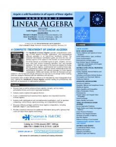
Course Information: Reference Texts:
VLSI Design Techniques for Analog and Digital Circuits by Geiger, Allen and Strader, McGraw Hill, 1990
CMOS Analog Circuit Design (3rd edition) by Allen and Holberg, Oxford, 2011.
7
Course Information: Reference Texts: CMOS: Circuit Design, Layout, and Simulation – Third Edition by J. Baker, Wiley, 2010.
Fundamentals of Microelectronics by B. Razavi, McGraw Hill, 2008
8
Course Information: Reference Texts: Design of Analog CMOS Integrated Circuits by B. Razavi, McGraw Hill, 1999
Analysis and Design of Analog Integrated Circuits-5th Edition Gray,Hurst,Lewis and Meyer, Wiley, 2009
9
Course Information: Reference Texts: Analog Circuits by Robert Pease, Newnes, 2008
CMOS Mixed-Signal Circuit Design – 2nd edition by Jacob Baker, Wiley, 2009
10
Course Information: Reference Texts:
Data Converters by Franco Maloberti,Springer, 2007
Voltage References by Gabriel Rincon-Mora, Wiley, 2002
11
Course Information: Reference Texts:
Switched-Capacitor Techniques for HighAccuracy Filter and ADC Design by Patrick Quinn and Arthur Van Roermund, Springer, 2007
12
Course Information: Reference Materials:
13
Course Information: Grading: Points will be allocated for several different parts of the course. A letter grade will be assigned based upon the total points accumulated. The points allocated for different parts of the course are as listed below: 2 Exams 1 Final Short Quizzes Homework Lab and Lab Reports Design Project
100 pts each 100 pts. 15 pts. each 100 pts.total 100 pts.total 100 pts.
14
Course Information:
Design Project: The design project will be the design of an 8-bit to 10-bit digital to analog converter (DAC). Additional details about the design project will be given after relevant material is covered in class. The option will exist to have this project fabricated through the MOSIS program. The design should be ready for fabrication and post-layout simulations are to be included as a part of the project. There will also be an operational design project that will be graded as a part of the laboratory component of the course
15
Course Information: E-MAIL:
[email protected]
I encourage you to take advantage of the e-mail system on campus to communicate about any issues that arise in the course. I typically check my email several times a day. Please try to include “EE 435" in the subject field of any e-mail message that you send so that they stand out from what is often large volumes of routine e-mail messages.
16
Course Information: Course Wiki
http:/wikis.ece.iastate.edu/vlsi
A Wiki has been set up for circuits and electronics courses in the department. Links to WEB pages for this course are on this Wiki. Students are encouraged to use the Wiki to share information that is relevant for this course and to access materials such as homework assignments, lecture notes, laboratory assignments, and other course support materials. In particular, there is a FAQ section where issues relating to the material in this course are addressed. Details about not only accessing a Wiki but using a Wiki to post or edit materials are also included on the Wiki itself. Students will be expected to periodically check the Wiki for information about the course. 17
Topical Coverage • Op Amp and Comparator Design – Design strategies – Usage and performance requirements – Building Blocks • Current Mirrors • Common Source, Common Drain and Common Gate Amplifiers
– Simulation Strategies – Compensation – Amplifier Architectures 18
Topical Coverage (cont) • Data converters : A/D and D/A – Nyquist-rate – Oversampled (if time permits)
• Voltage References – Bandgap References – VT References
• Integrated Filter Design – Switched Capacitor – Continuous-Time
• Phase-locked Loops (if time permits) 19
The MWSCAS Challenge
20
The MWSCAS Challenge
• One letter grade increase in grade will be made retroactive if a paper relating to AMS circuit design is accepted and presented at the MWSCAS • This would be a great opportunity to make a technical contribution and get experience/exposure in the research community • Cost of attending the conference will be the responsibility of the student but the department and university often help cover costs if requests are made 21
The MWSCAS Challenge Suggested Topics:
• Dynamic comparator • Integrated temperature sensor
22
What is an operational amplifier ?
23
Fundamental Amplifier Design Issues • Designer must be aware of what an amplifier really is • Designer must be aware of the real customer needs • Design requirements for application-specific amplifier dramatically different than those of catalog part
• Many amplifiers are over-designed because real needs of customer not conveyed • Conventional wisdom will not necessarily provide best or even good or even viable solution 24
How does an amplifier differ from an operational amplifier? • When operated linearly, an operational amplifier is an amplifier that is intended to be used in a feedback application – Feedback is needed to improve linearity and gain accuracy
• The more general amplifier is generally used open-loop • Conventional wisdom : an open-loop amplifier is much simpler to design and use than an op amp, will have better high-frequency performance, and will be less linear 25
What is an Operational Amplifier? Lets see what the experts say !
Consider one of the most popular textbooks on the subject used in the world today
26
What is an amplifier? • Voltage Amplifier? • Voltage, Current, Transresistance, Transconductance • Physical stimulus to electrical output
• Many Amplifier Architectures Exist – Common Source, Common Drain, Common Gate, Operational Amplifier, Two-stage, OTA, Fully Differential, Single-Ended, Instrumentation, LNA, Current Mirror,….. 27
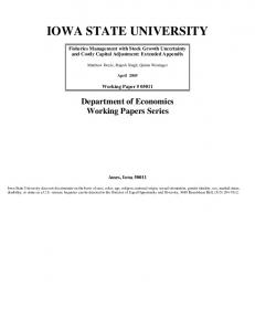
A classic textbook that has helped educate two generations of engineers
Sixth Edition Dec 2009
First Edition 1982
APCCAS 2010
28
In all editions, concept of the op amp has remained unchanged
APCCAS 2010
29
30
What is an Operational Amplifier?
Textbook Definition: • Voltage Amplifier with Very Large Gain −Very High Input Impedance −Very Low Output Impedance • Differential Input and Single-Ended Output
This represents the Conventional Wisdom ! Does this correctly reflect what an operational amplifier really is? 31 APCCAS 2010
Operational Amplifier Evolution in Time Perspective
Sedra/Smith View of Op Amp
2010
2000
1980
1960
1940
1920
APCCAS 2010
32
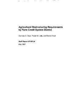
Consider some history leading up to the present concept of the operational amplifier
H.S. Black sketch of basic concept of feedback on Aug 6, 1927 Black did not use the term operational amplifier but rather focused on basic concepts of feedback involving the use of high-gain amplifiers
33
APCCAS 2010
Why are Operational Amplifiers Used? Harold Stephen Black (April 14, 1898 – December 11, 1983) was an American electrical engineer, who revolutionized the field of applied electronics by inventing the negative feedback amplifier in 1927. To some, his invention is considered the most important breakthrough of the twentieth century in the field of electronics, since it has a wide area of application. This is because all electronic devices (vacuum tubes, bipolar transistors and MOS transistors) invented by mankind are basically nonlinear devices. It is the invention of negative feedback which makes highly linear amplifiers possible. Negative feedback basically works by sacrificing gain for higher linearity (or in other words, smaller distortion or smaller intermodulation). By sacrificing gain, it also has an additional effect of increasing the bandwidth of the amplifier. However, a negative feedback amplifier can be unstable such that it may oscillate. Once the stability problem is solved, the negative feedback amplifier is extremely useful in the field of electronics. Black published a famous paper, Stabilized feedback amplifiers, in 1934.
34
Why are Operational Amplifiers Used? H. Black, “Stabilized Feed-Back Amplifiers”, Electrical Engineering, vol. 53, no. 1, pp. 114–120, Jan. 1934
“Due to advances in vacuum-tube development and amplifier technique, it now is possible to secure any desired amplification of the electrical waves used in the communication field. When many amplifiers are worked in tandem, however, it becomes difficult to keep the over-all circuit efficiency constant, variations in battery potentials and currents, small when considered individually, adding up to produce serious transmission changes for the over-all circuit. Furthermore, although it has remarkably linear properties, when the modern vacuum tube amplifier is used to handle a number of carrier telephone channels, extraneous frequencies are generated which cause interference between the channels. To keep this interference within proper bounds involves serious sacrifice of effective amplifier capacity or the use of a push-pull arrangement which, while giving some increase in capacity, adds to maintenance difficulty. However, by building an amplifier whose gain is made deliberately, say 40 decibels higher than necessary (10000 fold excess on energy basis) and then feeding the output back to the input in such a way as to throw away the excess gain, it has been found possible to effect extraordinary improvement in constancy of amplification and freedom from nonlinearity.” 35
A classic textbook sequence that has helped educate the previous two generations of engineers
Vacuum Tube and Semiconductor Electronics By Millman
First Edition 1958
First Edition 1967
APCCAS 2010
First Edition 1972
36
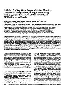
Millman view of an operational amplifier in 1967
Operational Amplifier refers to the entire feedback circuit Concept of a “Base Amplifier” as the high-gain amplifier block Note Base Amplifier is modeled as a voltage amplifier with single-ended input and output APCCAS 2010
37
Millman view of an operational amplifier in 1972
This book was published several years after the first integrated op amps were introduced by industry This fundamentally agrees with that in use today by most authors Major change in the concept from his own earlier works
38 APCCAS 2010
Seminal source for “Operational Amplifier” notation:
Seminal source introduced a fundamentally different definition than what is used today Consistent with the earlier use of the term by Millman
39 APCCAS 2010
Seminal Publication of Feedback Concepts:
Transactions of the American Institute of Electrical Engineers, Jan. 1934
Uses a differential input high-gain voltage amplifier
(voltage series feedback)
Subsequent examples of feedback by Black relaxed the differential input requirement APCCAS 2010
40
Operational Amplifier Evolution in Time Perspective
Black Introduces Feedback Concept
Black Publishes first Results on Feedback Amplifiers
Ragazzini introduces Operational Amplifier Notation
Millman and Ragazzini Sedra/Smith View of Op Amp View of Op Amp
2010
41 APCCAS 2010
2000
1980
1960
1940
1920
Do we have it right now?
Why are Operational Amplifiers Used? XIN
XOUT
A β
Input and Output Variables intentionally designated as “X” instead of “V”
Xout A AF Xin 1 Aβ
A
1 β
Op Amp is Enabling Element Used to Build Feedback Networks ! APCCAS 2010
42
What type of operational amplifier is needed? Example: Standard Textbook Analysis of Finite Gain Voltage Amplifier
R1 R2 V1 = VOUT + VIN R +R R +R 1 2 1 2 VOUT = -A V V1 R - 2 V R1 A VF = OUT = VIN R 1 1+ 1+ 2 R1 A V
R2 R1 VIN
V1
VOUT
AV
AV R - 2
R1
Implicit Assumption: Op Amp is a high gain voltage amplifier with infinite input impedance and zero output impedance Does this imply that operational amplifiers (at least for this application) should be good voltage amplifiers? 43
One of the Most Basic Op Amp Applications R2 R1 VIN
V1
VOUT
AV
Model of Op Amp/Amplifier including AV, RIN, RO and RL R2
R0
R1 VIN
V1 RIN
AVV1
VOUT
If it is assumed that AV is large,
RL
A VF
V V
OUT
IN
R R
2
1
Op Amp APCCAS This result is not dependent upon R2010 IN, R0 or RL
44
The Four Basic Types of Amplifiers:
Voltage
Transconductance
Transresistance
Current
APCCAS 2010
45
What type of operational amplifier is needed? R2 R1 VIN
V1
VOUT
AV
R2
R2 R1 VIN
R1 V1
VOUT GM
VIN
VOUT AI
How would this feedback voltage amplifier perform if the voltage op amp were replaced with a transconductance op amp or a current op amp?
46
What type of operational amplifier is needed? Consider using OTA for “Op Amp” R2
R1 R2 V1 = VOUT + VIN R1+R2 R1+R2 VOUT = V1 + IOUTR2
IOUT = -GMV1
R1 VIN
V1
IOUT
VOUT
GM
R - 2 GM R VOUT R1 A VF = = - 2 VIN R1 R 1 1+ 1+ 2 R G R -1 1 M 2
Voltage gain with feedback is identical to that obtained with a “voltage” Op Amp provided GM large ! 47
What type of operational amplifier is needed? Consider using Current Amplifier for “Op Amp” R2 R1
VOUT = IOUT R 2 VIN VOUT I1 = + R1 R2 IOUT = -A II1
A VF
VOUT = VIN
R2 R1 = 1 1+ AI -
VIN
IOUT I1
VOUT
AI
AI
R2 R1
Voltage gain with feedback is identical to that obtained with a “voltage” Op Amp provided AI large ! 48
What type of operational amplifier is needed? R2 R1 VIN
V1
VOUT
AV
All four types of amplifiers will give the same closed loop gain provided the corresponding open loop gain is sufficiently large !
Voltage
Transresistance
Transconductance
Current
A large gain is needed for an operational amplifier and if the gain is sufficiently large, the type of amplifier and the port input and output impedances are not of concern
49
Four Feedback Circuits with Same β Network R2 R1
R2 R1
V1
VIN
VOUT
VIN
VOUT
AV
AI
V R V R OUT
2
IN
1
R2
R2 R1 VIN
R1 V1
IOUT GM
VOUT
VIN
VOUT
I1
RT
All have same closed-loop gain and all are independent of RIN, ROUT and RL if gain is large 50 APCCAS 2010
Amplifier Types XOUT
A
XIN
XOUT A A 1 AF = = XIN 1+Aβ β
β Port Variables Xin Xout V V V I I V I I
Type of Amplifier A Voltage
Voltage
Amplifier Terminology Op Amp
Transconductance Transresistance Transconductance Transresistance Transconductance Transresistance Current Current Current
What type of operational amplifier is needed?
51
What type of operational amplifier is needed? Port Variables Xin Xout V V V I I V I I
Amplifier Terminology Op Amp Transconductance Transresistance Current
Ideal Port Impedances Input Output 0 0 0 0
Different types of op amps can be used in feedback amplifier but summing network performs different functions depending upon type of op amp used !
Dramatic Differences in Ideal Port Impedances!
52
Are differential input and singleended outputs needed? Consider Basic Amplifiers R1 VIN
R2
V1
VOUT
AV Inverting Amplifier R2 R1
V1
VOUT VIN
AV Noninverting Amplifier
Only single-ended input is needed for Inverting Amplifier ! Many applications only need single-ended inputs ! 53
Basic Inverting Amplifier Using Single-Ended Op Amp R2 R1
V1
VIN
VOUT
R2 R1 VIN
VOUT
AV
Inverting Amplifier with Single-Ended Op Amp 54
Concept well known
55
Hex Inverters in 74C04 much less costly than 6 op amps at the time!
APCCAS 2010
Fully Differential Amplifier R2 R1
VOUT
VIN R1 R2
• Widely (almost exclusively) used in integrated amplifiers • Seldom available in catalog parts 56
What is an Operational Amplifier?
Textbook Definition: • Voltage Amplifier with Very Large Gain −Very High Input Impedance −Very Low Output Impedance This represents the Conventional Wisdom ! Do we have it right now? Voltage Amplifier?
Low Output Impedance?
High Input Impedance?
Differential Input?
APCCAS 2010
Single-Ended Output?
Large Gain Large Gain?
!!! 57
Why are Operational Amplifiers Used? XIN
XOUT
A β
Input and Output Variables intentionally designated as “X” instead of “V”
Xout A AF Xin 1 Aβ
A
1 β
Op Amp is Enabling Element Used to Build Feedback Networks ! 58
What Characteristics are Needed for Op Amps? A 1 AF 1 Aβ β 1. Very Large Gain To make AF insensitive to variations in A To make AF insensitive to nonlinearities of A
59
What Characteristics are Needed for Op Amps? 1. Very Large Gain and … 2. Low Output Impedance 3. High Input Impedance 4. Large Output Swing 3. Large Input Range 4. Good High-frequency Performance 5. Fast Settling 6. Adequate Phase Margin 7. Good CMRR 8. Good PSRR 9. Low Power Dissipation 10. Reasonable Linearity 11.
…
60
What Characteristics are Really Needed for Op Amps? • For Catalog Component Those that are needed for the data sheet
• For Integrated Op Amp – Only those that are needed for the specific application – Often only one or two characteristics are of concern in a specific application
Avoid over-design to meet performance specifications that are not needed! 61