(This is the same approach that was used on the Centaur upper .... In this case the Atlas/Centaur Program dealt with a similar problem (not precisely the same ...
Lessons Learned from the Space Shuttle Engine Cutoff System (ECO) Anomalies Hugo E. Martinez 1 NASA/Johnson Space Center, Houston, TX 77058 and Ken Welzyn 2 NASA/Marshall Space Flight Center, Huntsville, AL 35812
The Space Shuttle Orbiter’s main engine cutoff (ECO) system first failed ground checkout in April, 2005 during a first tanking test prior to Return-to-Flight. Despite significant troubleshooting and investigative efforts that followed, the root cause could not be found and intermittent anomalies continued to plague the Program. By implementing hardware upgrades, enhancing monitoring capability, and relaxing the launch rules, the Shuttle fleet was allowed to continue flying in spite of these unexplained failures. Root cause was finally determined following the launch attempts of STS-122 in December, 2007 when the anomalies repeated, which allowed drag-on instrumentation to pinpoint the fault (the ET feedthrough connector). The suspect hardware was removed and provided additional evidence towards root cause determination. Corrective action was implemented and the system has performed successfully since then. This white paper presents the lessons learned from the entire experience, beginning with the anomalies since Return-to-Flight through discovery and correction of the problem. To put these lessons in better perspective for the reader, an overview of the ECO system is presented first. Next, a chronological account of the failures and associated investigation activities is discussed. Root cause and corrective action are summarized, followed by the lessons learned.
I. Introduction
T
he Space Shuttle Orbiter normally relies on a guidance velocity target cue as the nominal means of commanding Main Engine Cutoff (MECO). At commanded cutoff, a relatively small amount of propellant residual remains in both liquid hydrogen and liquid oxygen tanks. The usable portion of this residual is budgeted to cover nominal performance dispersions. The ECO system serves no purpose for such a nominal engine shutdown. In the event that excessive propellant is consumed or leaked, either or both liquid hydrogen and liquid oxygen may be depleted prior to the desired cutoff velocity. Since running out of propellant prior to shutdown is catastrophic, the engine cutoff system becomes critical for this case. The system is not armed until approximately 10 seconds prior to reaching cutoff velocity (the exact timing is dependent upon assuring 32,000 lbm of remaining total propellant calculated in real-time). Once armed, 2 of 4 sensors indicating DRY will trigger an engine shutdown. The software will “latch” a channel upon seeing a DRY for one clock cycle of the flight computers (40 milliseconds). However, if a sensor is indicating DRY at the moment of arming, its vote will not register towards an early cutoff. To help protect against this possibility, the launch commit criteria (LCC) require that none of the 4 sensors indicate DRY prior to liftoff. Both liquid hydrogen and liquid oxygen systems each utilize 4 sensors and use the same voting logic described. 1
NASA Subsystem Engineer (NSE), Space Shuttle Orbiter Main Propulsion System (MPS), Energy Systems Division, Mail Code EP4, NASA/Johnson Space Center, 2101 NASA Parkway, Houston, TX 77058. 2 NASA Chief Engineer, External Tank Project, Mail Code EE02, NASA/Marshall Space Flight Center, Huntsville, AL 35812. 1 American Institute of Aeronautics and Astronautics
The more relevant failure mode to this discussion is the failure to the WET state, which is the failure mode observed on several vehicle/tank combinations during ground testing and launch attempts since STS-114. If 3 of 4 sensors fail to the WET state, then the one remaining sensor can never satisfy the logic to initiate an in-flight early engine cutoff in the event it is needed. For this reason, ground checkouts since the 1986 Challenger accident have been performed during propellant loading to ensure that all four hydrogen and all four oxygen sensors have not failed WET. (More recently, and in response to these ECO system failures, only 3 of 4 hydrogen sensors have been required to pass this test.)
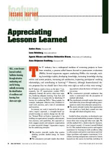
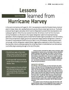
II. Liquid Hydrogen (LH2) Engine Cutoff (ECO) System Description The LH2 ECO sensors are installed on a shock mount inside of the External Tank (ET) near the bottom, and a 5% liquid level sensor is located several feet above it (see Figure 1). The sensors first experience liquid hydrogen conditions during propellant loading approximately nine hours prior to launch. These five signals pass through the aft feedthrough connector penetration in the lower tank wall. Lengths of wires are routed from the connector, through other ET factory connectors, to the Orbiter interface at the two Orbiter / ET electrical monoball connectors. The five signals are split as shown in Figure 2 and are run through port and starboard monoball connectors. Wires are routed into the Orbiter aft compartment to the avionics bay where the point sensor box (PSB) services the signal from the LH2 ECO sensors.
Figure 1. Liquid hydrogen ECO sensors installed at bottom of External Tank
Also serviced are the liquid oxygen ECO sensors, which are located in the Orbiter feedline, as well as various loading “point” sensors of similar design. These point sensors are located within the both the hydrogen and the oxygen external tank and serve to control liquid level during the various phases of propellant loading. Only the hydrogen ECO and hydrogen 5% sensor circuits are discussed in this paper as these were the only circuits involved in this failure investigation.
2 American Institute of Aeronautics and Astronautics
External Tank wall Orbiter aft compartment
Orbiter avionics bay 5
Starboard (LH2) monoball connector
LH2 sensor
Aft feedthru connector
Outputs to MDM
Port (LO2) monoball connector
5%
1
2
3
Point Sensor Box
4
Internal Plug External Plug Feedthrough connector
Monoball Connector PSB mounted on cold plate in AV Bay 5
Figure 2. LH2 Engine Cutoff System
The PSB, which is mounted on a coldplate in avionics bay 5, supplies a constant current to each sensor circuit and reads the voltage across each sensor’s thermosensor wire element. The box services all 24 sensors (8 ECO and 16 level sensors). The PSB contains 12 active signal conditioning cards mounted on a motherboard, two power supply cards, and an opto-isolator card that provides ground checkout capability. At ambient temperature, when the sensor wire resistance is high, the PSB provides a Output signal to the multiplexer-demultiplexer (MDM) Sensor loop to MDM since the measured voltage is above the preset Nominal output: 0 vdc if wet sensor trip level in the box. This DRY indication is fed 28 vdc if dry sensor to the flight computer MDM input from all four Point Sensor Checkout (DWW) ECO channels to vote for shutdown on either Box 28 vdc – wet sensor w/DWW commodity after arming as discussed previously. LH2 At liquid hydrogen temperature, the voltage drops Failure cases: sensor 14 vdc if open circuit in sensor loop below the trip level and the MDM receives no 0 vdc if open sensor circuit in PSB Checkout (sim) input signal (WET indication). commands
0 vdc if failed output to MDM
A WET state is also indicated should the PSB electronics fail to provide an output signal, or if an open circuit in the circuit between the PSB and Figure 3. Expected outputs for various scenarios the sensor develops. To help distinguish between a WET sensor output and a failed WET output, the box design includes self-check electronics which are activated by ground “sim” commanding (see Figure 3). The descriptive “dry when wet”, or DWW sim command, provides a supplemental voltage that exceeds the box’s trip level in order to override a WET condition. This ground checkout procedure has historically been conducted as a “snapshot” in time, typically over one minute, and only once propellants are loaded and in stable replenish. For this reason, the STS-114 and STS-115 ECO failures may have 3 American Institute of Aeronautics and Astronautics
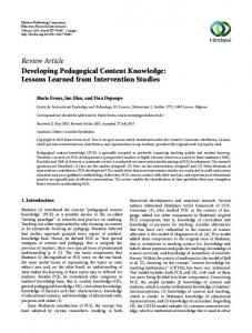
occurred much earlier than reported. (In fact, later usage on continuous DWW sim commands indicated that most failures were occurring hours earlier as the ET feedthrough connector was becoming wetted.) The sensor design uses a very fine platinum sensing element tensioned within a ceramic housing and brazed to gold plated contacts. To connect the sensor lead wires, the lead wires are brazed to terminal posts that are connected to the ceramic housing at the gold plating with swaged joints. Swaging of these tiny parts is a manual operation and subject to some variability. Loss of preload at this swaged connection was considered a potential cause of the intermittent open circuits observed, and will be discussed in more detail later. Figure 4 shows a highly magnified nanofocus X-ray image of a terminal post and swaged joint.
Figure 4. LH2 ECO Sensor in nano-focus view (left) and exploded view (right)
III. STS-114 Anomalies – Initial Investigation The first tanking test of STS-114 / OV-103 / ET-120 in April of 2005 experienced two LH2 ECO circuit failures. LH2 ECO #4 failed WET during snapshot sim command ground checkout of the system while fully loaded with propellants. During LH2 detanking, ECO #4 did not transition to DRY when the tank was dry as expected, but instead after 15 additional minutes had elapsed. A limited set of sim command combinations during this 15 minute time period exonerated the output side of the point sensor box to the MDM. Approximately 90 minutes after the tank was fully drained, LH2 ECO #3 failed WET and remained failed for an additional 90 minutes before returning to the DRY state. The fact that both failed ECO circuits share the port monoball connector led the team to include a fault at the monoball among the potential causes. Prior to the second tanking test in May of 2005, point sensor box serial number 108 was removed as suspect and replaced with serial number 110. The port monoball harness, which was new for STS-114, was removed and replaced. Drag-on voltage and current sensors and monoball temperature instrumentation was temporarily installed for this test, but no ECO anomalies were observed during cryogenic loading. The fact that the original external tank, ET-120, was retested successfully during this second loading seemed to indict the removed point sensor box and the original monoball harness. By the time of the July 13, 2005 attempted launch of STS-114, both the point sensor box and the tank had been replaced (for unrelated reasons). Point sensor box serial number 111 had replaced 110, and ET-121 had replaced ET-120. The launch attempt was scrubbed when liquid hydrogen ECO circuit #2 failed snapshot ground checkout to the WET state. Note that this was the first failure involving the starboard side monoball connector. The sensor circuit recovered to the DRY state approximately three hours after the tank had been drained. Interestingly, circuit #2 failed again, this time about 20 minutes after it had recovered, and it remained failed for an additional 15 minutes. Now another point sensor box, new starboard-side monoball harness, and replacement ET had all been indicted. 4 American Institute of Aeronautics and Astronautics
Following the July 13, 2005 STS-114 launch scrub, several actions were taken to understand the anomalies. A comprehensive fault tree was developed to guide the investigation. An older design PSB was successfully tested for EMI at JSC, indicating that the more robust flight configuration would not be susceptible to this failure mode. The entire electrical path from the Orbiter point sensor box and through the sensors was verified via resistance checks and time domain reflectometry, and no indications of an open circuit were found at ambient temperature. Orbiter grounding points were checked and found to be slightly out of specification (and were corrected prior to STS-114 launch). In addition, various loading conditions, such as cold plate settings, purge flowrates, and electrical switching, were duplicated on the STS-114 integrated stack in an attempt to produce a repeat failure. The notable exception is that no cryogenic propellants were loaded for this reenactment. PSB s/n 108 and its mating 55P84 connector which had been previously removed were subjected to full acceptance tests, both of which were completed successfully. This test included thermal and vibration testing to levels above those seen on the vehicle during flight. The box was then torn down completely, and two discrepancies were found that appeared to be related to the two loading anomalies. A tear in the flexprint assembly, which is used to route signals from the box’s motherboard to its connectors, was found in the LH2 ECO #3 circuit (see Figure 5). The tear was determined to extend only halfway through the path and did not compromise the integrity of the circuit. It was concluded that the tear was created during installation of the motherboard / flexprint assembly into the chassis, since trimming of the assembly was apparently required to make it fit. The other discrepancy found was a broken cold solder joint at a resistor in the LH2 ECO #4 circuit, but this electrical path was also verified to be good under vibration loads and other testing at the card level. Several other discrepancies (missing conformal coating, debonded card guides, a debonded capacitor, soldering issues, etc.) were also noted, but none could be traced to either of the original failures. In conclusion, no direct cause for the intermittent open circuit could be found within PSB s/n 108 used in the first tanking test.
Figure 5. PSB s/n 108 inspection found two discrepancies. On left is shown a defective solder joint in ECO channel #4 resistor R109. On right is shown a tear in the ECO #3 flexprint. Both were found to be only coincidentally related to the ECO #3 and #4 anomalies. Prior to the second launch attempt of STS-114, the Mission Management Team (MMT) approved a conditional Launch Commit Criteria (LCC) that would permit launch with 3 of 4 functional ECO circuits given certain conditions. Integral to this temporary LCC was an ECO wiring swap that switched the ECO #2 sensor (the previously failed channel) with the ECO #4 sensor. If the failure recurred on channel #2, the logic held that the failure would likely be isolated to that card in the PSB, and launch could continue since it would not be considered a common cause. If the failure switched to channel #4, it would likely be associated with that sensor and again, launch could proceed. Any other failure signature would result in a launch scrub. In spite of not having removed and replaced any significant hardware, no repeat of the anomaly was observed, and launch was successful. In retrospect, the wiring swap and LCC change would have (and may have) allowed launch with a faulty feedthrough connector.
5 American Institute of Aeronautics and Astronautics
IV. Anomaly Investigation Continues Following lift-off of STS-114 on July 26, 2005, troubleshooting the removed hardware continued. The port monoball electrical harness was removed and tested, as was the entire length of wiring and connectors removed from between the monoball and the point sensor box. In August of 2006, PSB s/n 111 was also removed and retested on the bench. No fault was found with any of the removed hardware. To test the theory that the force of freezing water could separate the pins from the sockets, a monoball assembly pulled from spares was tested at cold temperature with water. Five thermal tests were conducted down to -60 deg F, the measured minimum temperature of the port monoball during cryogenic loading: a dry test, one with water finely misted on the connectors prior to mating, one with water sprayed on the connectors prior to mating, one with pooled water in the sockets, and the final test with the connectors mated and frozen while under water. Only the final, unrealistic case was successful in inducing an open circuit. The pooled water test resulted in a slight decrease in the measured current. The conclusion was that the monoball connector was likely not the cause of the anomalies given expected levels of moisture intrusion while mated. Due to the foam loss events that occurred on STS-114, further flights were on hold while the ET foam IFA investigations progressed. During this timeframe, the ECO anomalies were also being further investigated. One area of increased scrutiny was the ECO sensors in the tank. A theory had been proposed which suggested that an intermittent electrical connection could exist at the sensor leadwire-to-terminal post swaged connection. This theory attempted to explain why a sensor could fail upon the first tanking and subsequently “heal” and function nominally in subsequent tankings, which was a characteristic exhibited by the recent anomalies. This theory was based mainly upon the fact that the sensors were acceptance tested using liquid nitrogen which, at -320 degrees F, is about 100 degrees F warmer than liquid hydrogen and may not adequately condition the swaged joints thermally. Furthermore, ET identified that processing issues associated with the swage joints had developed in the 1996 timeframe, and sensors associated with anomalies also happened to have been manufactured during this period. The manufacturing issues mainly involved tooling that tended to produce swage joints with characteristics more prone to joint loosening. To test the theory that the ECO sensors were behind the anomalies, in December, 2005 the NASA Engineering and Safety Council (NESC) sponsored testing of 50 sensors in liquid hydrogen in conditions representative of multiple tankings. These tests showed no anomalies, and high speed monitoring instrumentation showed extremely stable voltage responses. Although the tested sensors were manufactured in the 2002 timeframe, post-test nanofocus X-ray inspection of those sensors showed swage joint characteristics that were often of poor quality, similar to those produced in the 1996 timeframe. The NESC and Marshall Space Flight Center (MSFC) analyses of sensor swage joints indicated some further minor issues, but nothing that could have been attributed to causing the anomalies. The STS-114 foam loss IFAs resulted in ET-120 being returned to the Michoud Assembly Facility (MAF) for further foam investigations. This permitted tank entry and removal of the LH2 ECO sensors, two of which were involved in the initial anomalies. One of these showed “marginal” swage characteristics, and an open circuit could be forced to occur with this sensor by wiggling the lead wires. However, this sensor functioned acceptably when tested cryogenically. The other implicated ET-120 sensor showed robust swage characteristics. In the months that followed, a great deal of investigation resources was devoted to the study of the sensors. In summary, while there were shortcomings identified with the swage joints on the ECO sensors, the mounting body of evidence was not indicative that the ECO sensors were at the root of the anomalies. However to address concerns relative to poor swage characteristics and the potential for sensor reliability issues, the ET project began the practice of replacing the LH2 ECO sensors in all future tanks (beginning with ET-119/STS-121) with nanofocus X-ray screened sensors exhibiting good swage characteristics and also addressed the manufacturing issues at the ECO sensor vendor. A component common to all the observed anomalies was the aft LH2 feedthrough connection, through which all of the 4 LH2 ECO circuits and the LH2 5% loading sensor circuits pass. To investigate the ET feedthrough connector as a cause of the anomalies, the feedthrough from ET-94 (which had been decommissioned to a test article) was removed, inspected, and cryogenically tested while continuously monitoring circuit performance. No anomalies were observed. It is important to note, however, that the external plug was de-mated from the feedthrough and left on the ET-94 harness and was not tested. Additionally, a complete feedthrough connection (external plug, feedthrough, internal plug) was taken from stores and put through cryogenic testing, again with no 6 American Institute of Aeronautics and Astronautics
issues. In a further test, the external connector was intentionally contaminated with water and tested in liquid helium controlled to liquid hydrogen temperatures. Again, no performance issues were observed. After ET-120 was slated for refurbishment, physical access was made available to the tank which permitted removal of the LH2 feedthrough. Due to the desire to bring this tank back to flight status within schedule requirements, the external plug was de-mated from the feedthrough and disassembled so that the harness wires could be cut at the socket crimps. This preserved sufficient length of harness wires to allow a new plug to be “re-pinned” in-situ, minimizing removal of Thermal Protection System (TPS) foam and cable trays. Lab analysis was performed on the removed connector and feedthrough, and no obvious evidence was found that would indicate that the feedthrough had contributed to the anomalies. After STS-122, this conclusion would be revisited, however.
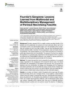
V. Failures Continue By the time of the STS-121 July 2006 attempts, the launch commit criteria had been relaxed to allow 3 of 4 LH2 ECO’s functional only on the second launch attempt; 4 of 4 otherwise. This logic assumed that a failed circuit would remain failed or would fail independently again. Continuous DWW sim commands had been implemented on all eight ECO circuits to determine exactly when the failure was occurring. This time an ECO failure did not occur – instead, the LH2 5% sensor failed the snapshot ground checkout (failed WET). The launch was scrubbed for weather, and the same failure repeated the following day, as well as during the subsequent loading on launch day. Because continuous DWW sim commands are only applied to the ECO sensors, the time of each of the 5% sensor failures was not known. The failure persisted during ascent past the point where the tank should have dropped below the 5% mark, indicating a sustained WET failure. The fact that the LH2 5% sensor goes through same ET feedthrough connector as do all of the LH2 ECO sensors tends to indict the feedthrough connector design. Interestingly, since the ECO sensors had been replaced with nanofocus X-ray screened sensors, and the 5% sensor had not, the repeated failure of the 5% sensor during consecutive loadings was interpreted as reinforcement of the launch commit criteria as written and of the swage theory as the cause. The STS-115 launch scrub on Sept 8, 2006 was meaningful in that the continuous DWW sim commands were finally successful in time-tagging the failure: about 40 minutes after the sensors were wetted, or about 15 minutes after the feedthrough connector was wetted, LH2 ECO # 3 had failed WET. It was also a meaningful data point in that the LH2 ECO sensors were built in 2003, whereas earlier failures had all occurred with suspect 1996 sensors Loading
Tanking Test #1
STS-114 Scrub 1
STS-121 Scrub 1
STS-121 Scrub 2
STS-121
STS-115 Scrub 1
STS-122 Scrub 1
STS-122 Scrub 2
STS-122 Test
Date
4-13-05
7-13-05
7-1-06
7-2-06
7-4-07
9-8-06
12-6-07
12-9-07
12-18-07
Failure
ECO#4
ECO#2
5%
5%
5%
ECO#3
ECO#3, #4
ECO#3
ECO#1
Detected at replenish check.
Detected at replenish check.
Detected at replenish check.
Detected at replenish check.
Detected at replenish check.
~ 40min after going wet.
~ 35min after wet 5% detected at replenish check. ECO #1 ~2hrs post drain.
~24 min after going wet.
~28min after wet. ECO #2, #3 intermittent. ECO#3 isolated with TDR.
ECO#3 post-drain
PSB serial #
108
111
112
112
112
109
109
109
109
Orbiter
OV-103
OV-103
OV-103
OV-103
OV-103
OV-104
OV-104
OV-104
OV-104
1803121
1764189
1764189
1764189
1764189
1803121
1803120
1803120
1803120
1790311
1790311
1790311
1790311
1790311
1790312
1790312
1790312
1790312
120 ’96
121 ’96
119 ‘96
119 ’96
119 ‘96
118 ’03
124 ‘03
124 ‘03
124 ‘03
Post-swage nano, washer heights
Postswage nano, washer heights
Post-swage nano, washer heights
Monoball Harness LH2 LO2 ET & Sensor vintage
Figure 6. Summary of ECO System Failures since RTF 7 American Institute of Aeronautics and Astronautics
installed. Post scrub troubleshooting using sim commands (with propellants loaded) found no other suspect channels, verifying same signature open circuit condition on a single channel. The failed channel was observed to transition to the proper DRY state approximately 5 hours after the other three LH2 ECO sensors transitioned to dry during the scrub de-tanking. Believing the failure to be isolated to a single channel, likely a sensor or associated wiring, the Program adopted a deviation to the launch commit criteria in order to attempt a launch the following day with 3 of 4 functional circuits. All four ECO sensors performed normally during the MPS level sensor checks during tanking for the September 9, 2006 STS-115 launch. The Shuttle Program approved an unconditional 3 of 4 LCC on November 16, 2006. Although no root cause had yet been found, all point sensor boxes scheduled for flight had been subjected to an enhanced acceptance test procedure, although further enhancements in testing were incorporated later. In addition, all of the future ET sensors had been built using improved manufacturing techniques, and again further enhancements (“before and after” Belleville washer height measurements). Part of the Program’s rationale in accepting 3 of 4 sensor circuits for launch was that additional prelaunch and flight monitoring capability had been added to OV-104 in the way of differential voltage measurements. These voltage measurements added the capability to isolate and characterize future ECO system anomalies if similar to the ones already experienced. This modification utilized existing dedicated signal conditioners and MDM’s, but required two wires and two resistors be added between the two Orbiter wiring splices and the signal conditioner in the Avionics Bay. However, the instrumentation was deleted from OV-104 for STS-117 when testing at the JSC Software Avionics Integration Laboratory (SAIL) facility found an unexpected characteristic of the PSB: shorting one sensors’ leg to ground was found to cause a false discrete indication in the companion channel’s output, either a WET or a DRY depending on the quality of the short circuit. While this characteristic was completely unrelated to the added instrumentation, it was decided to pull the instrumentation off OV-104 for fear of other undiscovered PSB characteristics that might somehow be made worse with the instrumentation leads installed. After a better understanding of this characteristic was developed, the voltage instrumentation was put on OV-105 for STS-118 and subsequent missions and has performed nominally. This time, an additional resistor was added on the return leg from the sensor in order to mitigate the risk of a false discrete indication due to a shorted companion channel. All vehicles subsequently received this modification. In late 2007, it was found that recontacting an open circuit could result in an intermittent DRY indication – a flash characterized in the lab as lasting between two and 10 milliseconds. Since the flight computers sample this analog output every 40 msec, the odds of registering a DRY flash were considered relatively high. A majority of the channels in the two PSB’s tested exhibited this characteristic due to their individual electrical components specification tolerance stackup. Two or more DRY indications within the 10 second window between arming and guided MECO would result in an inadvertent engine cutoff. If the cutoff occurred during approximately the first four seconds within this window, a loss of vehicle could occur. Launching with a known open circuit (which might recontact during ascent, giving DRY flashes with each recontact), would put the system only 1 additional failure away from this loss of vehicle scenario. However, with the lack of ECO failures since STS-115, the LCC remained 3 of 4 as accepted a year before. The addition of the voltage instrumentation for STS-118 (OV-105) gave insight into a problem in an ECO sensor circuits and help pinpoint its location. It provided the ability to distinguish between a nominal WET indication and a failed WET indication under T-9 minutes, after DWW sim commands are removed. The instrumentation would output approximately 13 volts if an open circuit developed in the PSB excitation / return loop to the sensors and would output zero volts if an open circuit existed in the PSB itself. To at least partially exploit this new capability, a new set of launch commit criteria (LCC) was created and documented as MPS-53. This new LCC would become effective only in the event that 1 discrete output had failed previously in the countdown. Because analysis found it difficult to distinguish between a failed zero voltage case and a lower-tolerance nominal WET volt case, it was decided that it would protect only for the 13 volt case. The new LCC was effective from T-9 minutes (at sim command removal) to T-5 minutes and would be implemented manually. This LCC would be renewed on a oneflight basis through STS-124.
8 American Institute of Aeronautics and Astronautics
VI. STS-122: ECO Failure Captured By December 2007, no ECO or 5% failures had been experienced on four successive launches. Had a single LH2 ECO failure occurred, launch would have proceeded after satisfying certain preplanned steps aimed at verifying no obvious common cause failure in the telemetry chain. The STS-122 ECO system responded by failing two LH2 ECO sensor circuits simultaneously, coincident with the timeline of the STS-115 failure. The LH2 5% sensor circuit failed the sensor “snapshot” checkout when it was performed later in the countdown, but its exact time of failure was not known. In addition, a third ECO channel failed WET after the tank was drained. All four failed circuits recovered post drain, although the 5% and ECO #4 recovered within 20 seconds of each other. These failures scrubbed the launch. Because of the obvious indication of a common cause potentially disabling the LH2 ECO system, the next launch attempt three days later was with a “5 of 5” criterion – that is, none of the LH2 ECO’s nor the LH2 5% sensor were allowed to fail. Besides being applied continuously to the ECO channels, continuous DWW sim commanding was applied to the 5% sensor for this next loading. This time, the STS-122 launch attempt was stopped with a single LH2 ECO failure - # 2. As part of troubleshooting, the liquid level was drained to just below the 5% sensor and held there for 4.5 hours. In theory, this allowed the now suspect ET feedthrough connector to warm up and correct itself while keeping the ECO’s covered in liquid. No such correction was observed. The tank was drained and ECO # 2 recovered about 45 minutes later. Approximately a week later, on December 18, 2007, a tanking test was devised to allow the use of time domain reflectometry (TDR) as a means of pinpointing an open circuit should it recur. Normal tanking proceeded as before, with continuous DWW sim commands applied to all five sensors of interest, and ECO’s # 2 and # 3 soon exhibited erratic behavior and then ECO # 1 failed WET roughly coincident with past failures (about 25-30 minutes after sensors were initially wetted). The ECO voltages indicated an open circuit somewhere outside of the PSB. TDR equipment was then plugged into staged break points and the open circuits were isolated to the area of the ET-125 feedthrough connector.
VII. Root Cause Determined The first launch attempt of STS-122 provided new key data that stimulated the development of a physics-based failure scenario. For the first time, simultaneous failures were observed on multiple channels, occurring nearly instantaneously. Additionally, timing data was again captured, and was for the most part consistent with the other timing data available from previous anomalies. The postulated scenario was that open circuits were occurring at the pin-to-socket connections within the external feedthrough plug, caused by intermittent loss of electrical contact. The loss of contact occurred due to relative motion between the pins and sockets moving the electrical contact points of the socket tines onto areas of the pins contaminated with cryogenically-induced transient nonconductive material. This scenario was presented to the PRCB on December 13. The tanking test on December 18 confirmed that the failure was indeed occurring at the feedthrough location, although the exact location within the feedthrough could not be resolved. The ET-125 feedthrough was later removed for testing with the external plug connection undisturbed. LH2 cryostat testing at MSFC successfully replicated the failure, and TDR was used to isolate the location more precisely to the external plug. Subsequent failure analysis of the hardware showed the presence of trace amounts of contamination and evidence of relative movement at the pin/socket locations. Potential sources of contamination were the breakdown of the silicone-based connector materials producing silicone oil, cryopumping of ambient air and moisture into void spaces within the connector during tanking, and to a very small degree Krytox grease used to lubricate various parts of the feedthrough assembly. Although the specific contamination culprit causing the open circuits could not be identified, each of these materials becomes electrically non-conductive at cryogenic temperatures, accounting for why the anomalies only occurred during tanking and cleared after drain. While the known times of failures and subsequent recoveries cannot be directly correlated to the thermal profile during loading and draining, respectively (some recoveries occurred as late as six hours after drain), each occurred during a transient thermal period. Significant variability is expected in the timing of the failure signature since the contaminant may be composed of varying amounts of silicone oil, liquid air, and water. The other key causal factor required for loss of electrical contact involves relative motion of the sockets in the external 9 American Institute of Aeronautics and Astronautics
plug with respect to the pins in the feedthrough. Motion could occur due to different coefficients of thermal expansion amongst the various materials in these components, pressure loading within the connector due to phase change of materials, and structural failure of materials constraining the sockets. Destructive physical analysis of the silicone grommet from the ET-125 external plug showed extensive cracking within this part, which would permit abrupt motion of the sockets relative to the pins and would explain the simultaneous failure of multiple circuits first observed on STS-122 launch scrub. Re-examination of the removed ET-120 external connector indicated similar cracking within the silicone grommet. An obvious question surrounds the increase in frequency of anomalies following Return-to-Flight. While there is no definitive explanation, there are several potential contributors. First, in 1986 the connector supplier changed the socket design from a leaf spring style to a split tine style, to reduce the potential for problems with loose or missing leaf springs and to simplify fabrication. The split tine socket, however, has significantly less electrical contact area, making it more sensitive to the failure mechanism (contamination with relative motion). Second, sometime between 1983 and 1990 the supplier changed the raw material formulation for the silicone grommet used in the external connector from a gum-based material to a liquid-based material. The liquid-based material had a much shorter cure time (8 hours versus 24) and may have contributed to an increase in silicone oil leaching into the connector over time. Finally, due to the extended stand-down in flights following STS-107, the post-RTF tanks had these feedthrough connections mated for much longer periods of time than normal. (Post-RTF average mated time was ~50 months, while pre-RTF average was ~14 months.) This could have contributed to an increase in silicone oil leaching from the grommet as well as increased compression set of the grommet. The latter could account for increased cryopumping into the connector and increased cracking and relative motion of the sockets. The only other time in the history of the program with similarly long mated times for this connector would have been following the Challenger accident. However, neither the change from leaf spring to split tine sockets nor the change to the silicone grommet raw material would have been implemented at that timeframe. Although these changes were captured in several requalifications of these components (required, for example, for the Super Lightweight Tank program), those qualification test articles were not subjected years of being mated prior to execution of those tests, and would not have revealed any time-dependant sensitivities.
VIII. Corrective Actions The most reliable way to mitigate the failure mechanism was to create a solid connection at the external plug to feedthrough interface. This was done by soldering the sockets to the pins. (This is the same approach that was used on the Centaur upper stage following ECO anomalies in the 1990s.) Additionally the external plug was replaced with a different (internal) style that utilized a Teflon insert rather than the silicone grommet insert. The holes in the Teflon insert were enlarged to allow the soldered sockets to slip freely through this insert, so in effect the redesigned external plug just served to provide strain relief to the now soldered external harness. No changes were made to the internal connection, as this connection is not subject to all the causal factors and not considered suspect. Figure 7 shows a close-up of the external harness sockets soldered to the feedthrough pins (prior to installation of the external plug). The redesign was qualified through cryogenic cycle and cryogenic vibration testing, followed by destructive physical analyses. The Figure 7. Soldered pins/sockets redesigned connector was installed in ET-125 at the launch pad and performed successfully on STS-122. The installation was performed on ET-126 (for STS-123) in the Vehicle Assembly Building (VAB), and installations for remaining tanks are being done at MAF. Further corrective actions include stricter controls on the application of lubricants on connector assemblies and insuring cleanliness of the GSE that mates to these connectors.
10 American Institute of Aeronautics and Astronautics
In addition to the various Orbiter-side corrective actions previously discussed, a permanent version of the MPS-53 LCC was approved in August of 2008. (MPS-22 remained at 3 of 4 functional, 4 of 4 WET as previously agreed, and in effect from T-9 minutes to T-31 seconds). The permanent MPS-53 was exactly like the flight-by-flight MPS53 which had been in effect since STS-118, but it would be effective down to T-31 seconds and would be automated. Like prior versions, MPS-53 would only be invoked if a discrete output had previously failed during countdown and then it would only monitor for the open sensor loop case (13.1 volts).
IX. Lessons Learned The lessons discussed here are based upon the perspectives of the authors. It is hoped that all those involved in the Shuttle Program, particularly all those who were involved in the exhaustive efforts to find and correct these anomalies, will carry their own personal lessons learned. Those lessons will likely be as diverse as the individuals who carry them. Some of these have already been documented within the NASA system, for example in the NASA Lessons Learned Information System (number 1844) and in the final report from the ECO System Anomaly Longterm Resolution Team. The interested reader is encouraged to review these references for additional viewpoints and technical data.
A. Lesson 1 - When something is going wrong, and there is no explanation for it, decisions probably should not be made based on expected future performance unless the consequences of being wrong are acceptable. Without root cause or at least a physics-based failure scenario explaining the ECO anomalies, backed up by supporting engineering data, the anomalies should be assumed to be able to reappear at any time. With the LH2 ECO anomalies, there appeared to be widely differing viewpoints on whether the consequences of “being wrong” were acceptable. Data was presented that indicated a very low probability that the LH2 ECO system would ever be needed, and most used that as rationale for accepting that risk. This allowed them to accept the modifications to the LCC, and to continue flying in general, with an unsolved problem. B. Lesson 2 - Remember Occam’s razor: the simplest solution is usually the best. Applied to the case of the ECO anomalies, this would imply that the simplest explanation is most likely correct. As the body of data began to grow, the explanation that made the fewest new assumptions was that the single component involved in all the anomalies (the LH2 feedthrough) was the culprit. However that is not where the emphasis was placed (see Lesson 3). C. Lesson 3 - Do not continue to support theories that don’t make physical sense. The idea that the sensors were the culprit was fairly widespread, and evidence of processing deficiencies and belief that a sensor could “heal” after one tanking contributed to this. However, significant test data did not support this, nor did the anomaly signatures such as multiple failures, when the failures occurred, and failures occurring after drain. But with no other viable explanations, the natural tendency was to focus on deficiencies. This undoubtedly drew priority and resources away from other potential causes.
D. Lesson 4 - Failures involving contamination should be expected to have a random signature. That is just the nature of contamination – sometimes it’s thick, sometimes it’s thin, sometimes it changes when the hardware is operated. When dealing with random electrical failures, this would be a good place to put priority. E. Lesson 5 - Be very aware of all the potential effects of using LH2. The environment inside an LH2 tank is cold, but fairly stable and benign. However, other materials do some strange and often unexpected things at these temperatures. Research into foam loss mechanisms is proving the power of phase changes that occur in many materials (air, for example) that, if not specifically accounted for through design, 11 American Institute of Aeronautics and Astronautics
will generally have unintended consequences. Most would not consider air an electrical contaminant, but it will become one at LH2 temperatures, as will trace amounts of almost anything not “solid” to begin with. F. Lesson 6 - Be aware of potential materials age-life issues. When planning component or qualification testing, at the very least consider potential age-related effects and whether there might be ways to explore accelerated aging prior to testing. Thoroughly assess each material for agerelated sensitivities, its aging state (e.g. is it stressed, etc.), and potential effects of aged conditions on the performance of the component and system.
G. Lesson 7 - Stay on top of vendor changes (and their subtier vendors, and their suppliers, etc.) This is a pervasive problem, and although systems are in place to ensure changes do not get made without being reported, it still occasionally happens. Oversight at vendor levels and below is costly. The Agency would be well served by exploring cost-effective ways to accomplish this.
H. Lesson 8 - Troubleshooting needs to be focused on actual, suspect hardware with the absolute minimum of disturbance. The difficulties of physically getting to the suspect components (sensors, wiring, feedthrough) on the ET-120 and later tanks essentially made these “off-limits” for inspection or removal, as the goal was to preserve this tank for flight with schedule getting priority. While this is understandable, given the likelihood that the anomaly source was elsewhere, taking the schedule impact up front may have helped get to root cause much sooner.
I. Lesson 9 - Elusive, intermittent electrical problems are more quickly solved by replicating all conditions present during the failure and using the suspect hardware. One thing was clear about the ECO anomalies – they only occurred during tanking. The program had to balance the potential of trapping an apparently random anomaly against the expense and hazard of tanking the vehicle, or decide to go remove all the suspect hardware and test offline and hope it showed up. The approach chosen was to try and develop rationale to keep flying and hope the solution would be found through investigation or just disappear entirely with partial reliability improvements in place.
J. Lesson 10 - When assessing an unexplained anomaly, search for similar systems and/or problems within industry or other government programs. In this case the Atlas/Centaur Program dealt with a similar problem (not precisely the same but similar enough) and identified a similar corrective action. This would have been valuable data for the investigation team to have had. Often these lessons are not captured in an industry-wide accessible database, and their discovery may require extra effort.
K. Lesson 11 - Continuous “DRY when WET” sim commands should have been used since the beginning of the Program since this is a screen for the most likely failure mode, fails WET.
L. Lesson 12 - With future engine cutoff system designs, consider software that would require more than one DRY instance per channel to initiate cutoff. Qualification of the system would of course require a high fidelity test setup with representative cryogenic flowrates using flight-like hardware and high-speed data acquisition. Alternately, ensure that system design does not allow for a DRY flash to occur upon remake of an inadvertent open circuit. 12 American Institute of Aeronautics and Astronautics
M. Lesson 13 - With future new engine cutoff system designs, insure that no grounding of one channel can result in false indications on a companion channel. This characteristic of the PSB was not known at the time of initial design or qualification; it was uncovered during bench testing in support of the investigation.
N. Lesson 14 - Assess benefit of enhancements realistically; do not unbalance the risk by taking advantage of a slight safety improvement. In this case, an MDM rewiring modification prior to STS-114 almost resulted in relaxing the LH2 and LO2 launch commit criteria from 4 of 4 required at launch to only 3 of 4 required. Were it not for the Program’s conservative stance following the 2003 Columbia accident, the ECO system launch rules would likely have been relaxed and an investigation would not have been initiated until multiple failures occurred.
O. Lesson 15 - Believe Failure Modes and Effects Analysis (FMEA), particularly where higher criticality single point failures are concerned. The Feedthrough connector was identified as a single point failure and no amount of improvement to other parts of the system can nullify that. Experience from STS-122 proved that the single point failure could and did fail.
P. Lesson 16 - Minimize electrical single choke points, particularly those that are expected to operate at liquid hydrogen temperatures. Early on, the risk trade between the risk of a common cause ECO system failure due to a compromised feedthrough connector and the risk of leakage due to multiple hydrogen tank penetrations was made, and the latter must have been deemed a greater concern. In retrospect, the risk of a hydrogen leak may have been a more readily controlled hazard.
Q. Lesson 17 - Commit to realistic use of Probabilistic Risk Analysis (PRA). The Program has committed to its use, but the 2005 common cause assessment was deemed excessively conservative by many. With STS-122 multiple ECO failures, the analysis was proven correct.
R. Lesson 18 - Connectors, pins, and sockets must be maintained free of contamination, particularly when exposed to cold environments in service.
13 American Institute of Aeronautics and Astronautics
Acronym List DRY DWW ECO EMI ET FMEA GPC GSE IFA JSC LH2 LCC LO2 MAF MDM MECO MPS MSFC NESC PRA PSB RTF SAIL TDR TPS VAB WET
(Not an acronym. Capitalized to show dry state of output) “Dry When Wet” ground sim command. Used to verify point sensor box ability to output a DRY discrete when sensors are reading WET. Engine Cutoff (system) Electro-Magnetic Interference Shuttle External Tank Failure Modes and Effects Analysis General Purpose Computer Ground Support Equipment In-flight Anomaly Johnson Space Center Liquid Hydrogen Launch Commit Criteria Liquid Oxygen Michoud Assembly Facility Multiplexer / de-multiplexer used for processing discrete output of point sensor box and routing to general purpose computer Main Engine Cutoff (as commanded by flight computers based on target velocity) Main Propulsion System Marshall Space Flight Center NASA Engineering and Safety Council Probabilistic Risk Assessment Point Sensor Box (originally known as Point Sensor Electronics Box) Return-to-Flight, in this case first flight since STS-107 Columbia accident Software Avionics Integration Lab Time Domain Reflectometry Thermal Protection System, foam in the case of the External Tank Vehicle Assembly Building (Not an acronym. Capitalized to show wet state of output)
14 American Institute of Aeronautics and Astronautics