USING LESSONS LEARNED FROM SPACE VHDL & FPGA'S HERE ON EARTH
Adam Taylor CEng FIET Chief Engineer – Electrical Systems | Space Imaging |e2v www.e2v.com
[email protected]
Version Control
Engineering Life Cycle
HDL Rules
Verification
Quality of Result
Scripting
PCB – Co Design
Documentation
Training & Development
Engineering Governance To ensure design quality regardless of end application the developing organisation must have a defined engineering governance policy Delivery Life Cycle Business Case Generation
Concept
Business Case Delivery
Initiation
Gate 1 Register of Interest
Execute (Doing)
Planning
Gate 2 Bid/No Bid IMPACTS
In-Service Delivery
Gate 3a Bid Release
In-Service
Gate 3b Contract Review/ Project Start
Gate 4 Delivery Review
Engineering Life Cycle Project Definition
Concept
Expression of Interest / RFQ
Implementation
Initiation
Kick OFF
Execute (Doing)
Planning
SRR
SDR
PDR
Requirements Baseline Established
Functional Baseline Established
Demonstration of Preliminary Design against Functional and Requirement Baselines
CDR / TRR / TRB
Demonstration of design maturity against Functional and Requirement Baselines
Ensures test articles, facilities, equipment personal and test procedure are available
Review of Test and qualification results against Requirements baseline
Closure
Gate 5 Out of Service Review
Gate 6 Disposal/Close
Version Control Enables baselines to be defined • We can roll back version's should we break it –and lets face it we do at times • Need to configure more the just the RTL and Test Benches but also constraints and scripts used in the build • There are a number of open source tools which can be used • Correctly done version control can aid reuse as you can have a central repository - Decreases development time
HDL Guidelines Enforce the use of best practice. These should reference the target technologies coding guidelines Examples include • library usage e.g. un/signed not std_logic_arith for mathematics. • Rules on Generics • Rules on state machines – One or Two Process, Unused States • Reset Structures • Synchronisation structures • Latches and Sensitivity List
Scripting Simulation, Synthesis & Place and Route contain many SW selectable options. Scripting enables easier repeatability of stages – we do not need to remember
PCB Co Development We need to ensure the Schematic and PCB are synchronised. Tools like IO designer enable the FPGA IO design and the PCB to be developed concurrently. Also need to consider the power dissipation for the thermal analysis to ensure the device stays within de rating limits
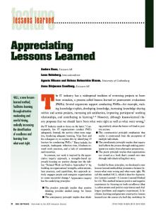
Documentation Possibly the part engineers like the least however • Communicates performance required of the design • Details the architecture and design solution used to address those requirements • Enables the verification approach to be outlined • Verification results provide formal evidence of the requirements being achieved.
Documentation
Training & Development The one HR and Management love, but we need to ensure the development team • Are up to date with tool required to do the job • Are up to date with the latest design and verification methodologies • Get time to experiment • Have career aspirations and goals listened too • Have a training needs analysis identifying training needed for project • Some of these are responsibility of engineers a part of their continuing professional development
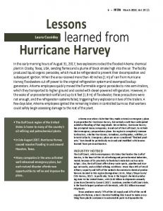
Verification • What is the AIM of it ? Prove the design meets the specification • Verification can take longer and be more complicated than the RTL design. • What strategy to undertake – Model based – Constrained Random – Worst Case
Verification
Boundary & Corner Cases A boundary condition is a when one of the inputs is at its extreme value
A corner case is when all inputs are at their extreme value
Code Coverage Code Coverage enables the UUT is properly exercised by the test bench • • • • •
Statements - each executable statement is examined to determine how many times is executed. Branch, all possible IF, CASE, SELECT, branches are executed Conditions and sub conditions within a code branch are tested to see what condition caused it to be true. Paths, all paths through the HDL are traversed to identify any untraveled paths. Triggering, monitor signals in the sensitivity list of VHDL processes and wait statements.
Achieving 100% in the above parameters will not prove the UUT is meeting functional requirements however, it does easily identify sections of the UUT which have not been exercised by the test bench
The Detail
Harsh Environment – Getting There Launch • Acoustic Loading • Vibration • Random and Sine • Shock • Depressurisation – Venting • Electro Magnetic Interference
Harsh Environment – Operating there Operation • Temperature • Radiation • Reliability • Long Operating life • Electro Magnetic Interference
Of course depending upon the end application your approach can be tailored to best suit
Dynamic Environment The main shock and vibration environments occur during – Launch – Payload Separation from the launcher – Extension of solar panels – Extension of antenna reflectors
Depending upon the role of your equipment e.g. platform or payload it will be either unpowered or powered during launch. It is mainly platform subsystems which are powered during launch and therefore must operate correctly through out launch. Unpowered equipment must be capable of operating post exposure to the dynamic environment
Dynamic Environment An example the vibration profile can cause, we recently had issues with an equipment a subcontractor supplied. Upon further investigation it was found vibration was causing bond wires within a FPGA to cause glitches and result in a un recoverable state. Often it is late in a project when the qualification is undertaken hence the cost of failures can be significant not only financially but also effecting launch dates.
Dynamic Environment Development of a structural model early in the programme which is representative of the final design. Daisy chain devices can be purchased from many component suppliers in the same packaging which allows you to monitor the package mounting to ensure it can survive or operate within the dynamic environment. While this can be tested early it is by no means cheap, but it is cheaper than finding out during the qualification programme.
Thermal Is Space Cold ? Cosmic background radiation is -270C But there is more to it than that, Three methods of heat transfer – Radiation – All things greater than 0K emit radiation, most common example Sun – Conduction – Materials in direct connection with each other. – Convection – Requires an atmosphere
Spacecraft to spacecraft – radiation only Internal to spacecraft – radiation and conduction What do you think the major challenge in space is ?
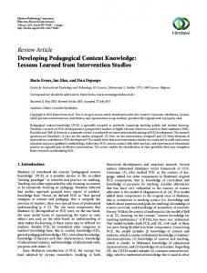
Thermal
Thermal Both the equipment and FPGA will be required to operate across wide temperature ranges. It is typical for your design to have to meet three operating temperature ranges and still operate. – Operating Temperature, the normal operating temperature in orbit (20C to 60C) Applicable to all units – Acceptance Temperature, this is the temperature at which the design analysis should be conducted this is normally operating temperature +/- 5C – Qualification Temperature, this is the temperature the unit has to operate at during qualification normally operating temperature +/- 10C These temperatures will depend upon the spacecraft bus your payload is flying on.
Thermal Performance in the thermal environment is tested during thermal vacuum testing (TVAC) Why TVAC ? A higher temperature rise will be exhibited in components than standard thermal testing by between 10 and 20C. This can have a significant effect upon both the power required and the timing performance of your design.
Different types of radiation? Total Ionizing Dose (TID) Total Non Ionizing Dose (TNID) Single Event Effect (SEE) Deep Dielectric Discharge (DDD)
The Bit Flip
Single Event Effect Mitigation
Error Detecting Code & Correction
Clocks Very simple approach which is easily often to get wrong – – – –
Consider Oscillator start up time in the design analysis Carefully Plan the use of Clock Global and Local Clock resources Be very careful about crossing clock domains Ensure Asynchronous inputs are synchronised to the clock domain
Reset • • • •
Do not rely upon the default value at power up Reset needs to be Asynchronous Assertion – See clock start up time Synchronous De Assertion – Prevents the risk of meta-stability when cleared Ensure Outputs are reset to de assert peripherals especially bi directional busses
Global TMR • • • •
Triplicates all resources in the design including IOB and Clocks, reset trees Protects entire design from SEU and SET Protects from errors in configuration memory – but it does not correct them More complicated to implement – – – –
•
Areas Penalty reduces size of design to be implemented Validation is increased need to ensure final bit file is implemented as desired Will have an impact upon power of the design Need to manage clock skew carefully
TMR needs to re synchronise
Global TMR
Large Grain TMR • • • •
• • •
Triplicates all resources in the design including IOB and Clocks, reset trees, HOWEVER Flip Flops are not voted upon Uses one voter prior to the output of the three modules. Unlike Global TMR the FF are not resynchronised Can be used with partial reconfiguration to reconfigure a incorrect chain if required. It has minimal domain cross points unlike global TMR. Mitigates both configuration and user logic errors Like global TMR it has area and power penalties
Large Grain TMR
Local TMR • • • •
Triplicates Flip Flops and votes on the output Best used in slow deigns to stop SET being clocked in Offers area advantage as combinatorial logic is not replicated Mitigates both user and configuration memory
State Machines The Unmapped State
State Machines How can we protect state machines
State Machine What does a Hamming code of three mean? Adjacent States 001 State 110
000
010
For each state with n number of bits there are also n adjacent states
State Machines What it looks like in VHDL, when we automatically generate a package to support Hamming three states.
State Machines What it looks like in RTL
Counters Many Engineers look just for the terminal count of the counter for example IF count = 9 THEN However SEU can result in the value of the counter being >= 9 In such a case the counter would fail, and the effects may propagate Instead use IF count >= 9 THEN In the worst case the timer will action early (which can be mitigated at FPGA level) rather than lock up the counter
Further Reading NASA Guide FPGA Lesson Learned From FPGA ESA Micro Electronics Adiuvo Engineering