This density is important to best quantify non-rigid surface motion, which is ... We restrict our non-rigid registration to the domain of the range image for now.
Level-set surface segmentation and registration for computing intrasurgical deformations M.A. Audette' and T.M. Petersb aMontreal Neurological Institute (McGill University), 3801 University, Montreal, Canada bThe John P. Robarts Research Institute, London, Ontario, Canada
ABSTRACT We propose a method for estimating intrasurgical brain shift for image-guided surgery. This method consists of five stages: the identification of relevant anatomical surfaces within the MRI/CT volume, range-sensing of the skin and cortex in the OR, rigid registration of the skin range image with its MRI/CT homologue, non-rigid motion tracking over time of cortical range images, and lastly, interpolation of this surface displacement information over the whole brain volume via a realistically valued finite element model of the head. This papers focuses on the anatomical surface identification and cortical range surface tracking problems. The surface identification scheme implements a recent algorithm which imbeds 3D surface segmentation as the level-set of a 4D moving front. A by-product of this stage is a Euclidean distance and closest point map which is later exploited to speed up the rigid and non-rigid surface registration. The range-sensor uses both laser-based triangulation and defocusing techniques to produce a 2D range profile, and is linearly swept across the skin or cortical surface to produce a 3D range image. The surface registration technique is of the iterative closest point type, where each iteration benefits from looking up, rather than searching for, explicit closest point pairs. These explicit point pairs in turn are used in conjunction with a closed-form SVDbased rigid transformation computation and with fast recursive splines to make each rigid and non-rigid registration iteration essentially instantaneous. Our method is validated with a novel deformable brain-shaped phantom, made of Polyvinyl Alcohol Cryogel.
Keywords: Image-guided surgery, brain shift , range-sensing, registration, level-set segmentation
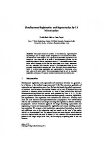
1. INTRODUCTION Image-guided surgery is a technique whereby a model of a patient's head, typically featuring skin, cortex and lesion surfaces, is constructed from a set of segmented MRI/CT images and is then registered with the patient's head in the OR, using a locating device. The usefulness of this technology hinges on the accuracy of the transformation between the image and patient spaces. However, this transformation becomes less accurate as the brain shifts during surgery. To alleviate this problem, we propose a method for estimating brain shift which is characterized by the following stages (see figure 1): S
semi-automatic identification (segmentation) of relevant anatomical surfaces within the MRI/CT volume;
. range-sensing of the skin and cortex in the OR; . rigid registration of the skin range image with its MRI/CT homologue, which will serve as a baseline for the next stage; . non-rigid motion tracking, over time, of the cortical range image;
. and lastly, interpolation of the resulting surface displacement over the whole brain volume, assuming null displacement at the base of the skull, via a realistic finite element model (FEM). Our discussion here focuses on some of the machine vision issues listed above, namely identification of anatomical surfaces by level-set segmentation, range-sensing of visible anatomical surfaces, and cortical motion estimation. We
Part of the SPIE Conference on ImaQe Processing • San Diego, California • February 1999 110
SPIE Vol. 3661 • 0277-786X1991$lO.OO
Surface Identification
Range Image Acquisition
Range to MRI Rigid Registration
\ Range Image Non-Rigid Registration
FEM-based Displacement Interpolation
Figure 1. Brain shift estimation framework also describe a novel phantom design, whose material properties and shape are very good approximations of those of the human brain. This phantom will be used to validate our research on intrasurgical motion estimation.
Intrasurgical brain shift has been documented by Maurer27 and by Skrinjar,36 who attribute it to the effect of gravity, to a gradual seepage of CSF, to cerebral blood volume manipulation, and to the effect of certain drugs. Existing techniques for dealing with brain shift include intraoperative MR scanners27 and intraoperative ultrasound.'2 Miga28 and krinjar36 have independently developed FEM-based solutions in the same spirit as ours, although we emphasize the estimation of a dense surface displacement function, which is then interpolated over the brain volume (assuming null displacement at the base of the head), whereas their work focuses on the physical modelling which most realistically performs this interpolation or generically models this phenomenon. Our goal is to first demonstrate the proof of concept of a technique integrating surface displacement estimation and finite-element modelling, with a highly accurate range-sensor and a brain-shaped phantom made of a wellcharacterized elastic material. Eventually, our physical model will account for the fluid component of brain tissue, for a clinical validation stage. A method based on surface displacement estimation and finite-element modelling is extremely compelling from a strictly economic standpoint, as the combination of range-sensor and FEM software is nearly an order of magnitude cheaper than an ultrasound machine, and close to three orders of magnitude cheaper than an intraoperative MR scanner. Intraoperative MR remains the gold standard in brain shift estimation, and ultrasound is likely to provide good feedback on tissue resection. However, our method is attractive because of its commercial potential, and because of the speed, ease-of-use, and accuracy of range-sensors and state-of-the-art physical models. Moreover, our method does not preclude the integration of resection information, provided by a tracked hand-held probe35 for example. Lastly, a surface displacement-FEM paradigm, minus the range-sensor, constitutes the foundation of a realistic patient-specific surgical simulation system, at the cost of a haptic feedback device,'7 some optimization of the FEM computation for this environment,4 and modelling of surgical tools.3' Further author information: (Send correspondence to MA. Audette) M.A. Audette: E-mail: maudette©nil.mni .mcgill.ca T.M. Peters: E-mail: tpeters©irus.rri .on.ca
111
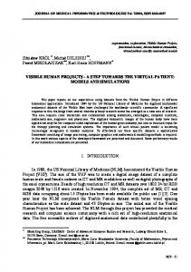
Figure 2. Ivel—set segiiient atiun : a) unhedding of 2D contour estimation iii 3D; (h) typical results in 31). f ir elastic brain phaiit oni ( front an initial surface dehned as the scan perimeter). displayed on VIPEH plat b wni current lv used for iniagi-guided surgery.
This paper is organized as follows After the mtroduction. a presentation of our materials and methods is given 2. nanmelv level—set segmentation of the skin and cortex ( 2.1). range—sensing of the same two surfaces in t lie OR ( 2.2). cortical motion estimation ( 2.3). and an elastic brain phantom ( 2.4). The results appear in 3. and we discuss the results and future directions in 4. in
2. MATERIALS AND METHODS 2.1. Level-set surface segmentation The skin and cortex surface identification technique is an uitplemnentatioti of a recent algorithum, known as a su,fote evolution niodel. which imbeds 3D surface segnlentatioli as the zero level—set of a ID nioviuig front 'I'. as illustrated in figure 2(a) for the problem of lesser dinuensionalitv. namely identifying 21) contours. This approach possesses certain advantages over physically—based niodels. in particular its capacit V to capt tire a large variety of topologies and a relative insensitivity to initial cot1ditn)Iis. Surface evolution models have already loon tieinomistrated on this part of the anatomy: Zeng's model.4 featuring two evolving surfaces which are bound to each other by a distance constraint. robustly segments the inner and outer surfaces of the cortex. Iti general. a surface evolution model is initialized by a user—defined surface completely inside (or outside) the desired anatontical boundary. The front t lien moves in a. strictly outward (inward) manner according to the following equation46
= (.r.
)MV'PH(H+v)
+ Vth'P.
where itmean curvature H of the front is given by die(V'.I' / V'I' ). This model features a diffusive term
1)
H which
tends to smooth out the front. a hyperbolic terni H V Ii v winch pushes the front forward, and two itiage ternis: a speed function which slows down the front near strong gradients. and a so—called 'doiihlet " term V€ V'l' winch prevents the front front overshooting these gradients. The user—defined surface is processed in the initialization by computing front it a ,siqned distuitce function. with interior poults typically labelled negative, and exterior putt s positive. This distance function constitutes the initial front 'P. at I = 0. rhe diffusive ternu is esti nated by central differences and provides tile niodel with some imnntuiut t () low—contrast patches along the boundary. The hyperbolic tern! acts analogously to Cohen's balloon inflation (or deflation. for nit inward front) force. pushing the front towards the desired boundary, but in a discontinuity—preserving manner.
This terni is estiniateci with upwind differencing.'32 which tends to not. consider inforniat ion beyond a sharp 'lhis so-called geodesic model has been derived by ('aselles from first principles, in an energy minization framework, for 2!) contours. In a manner analogous to cla.ssu'al level-eel extended to 3D surfaces ,° and also implemented independently by 'tannenhaums group. models derived earlier by Casetles7 and by Malladi.2C whose evolution according to the geometric heat equation leads to the fastest ('tii've or surface shrinking on the basis of Luclidean arclength in 21) or surface area in 3D. the geodesic model is characterized hy otOinial minimization of a conformal metroc which factors image information into the definition of arclength or surface area.4
112
discontinuity along the boundary, in evaluating derivatives, thereby preserving discontinuous topology. The image cofactor çb represents a speed which tends to zero at strong gradients and is expressed as 1
1 + IIVG * I(x, y, z)If '
(2)
where typically n=1, 2 or 3 and G usually is a Gaussian filtering kernel. There are faster alternatives to classical Gaussian filtering, such as recursive implementations of near-Gaussian operators.29'42 However, given that we want to eventually register the result of this operation with a cortical range image, we prefer to base our image function on anisotropic diffusion than on isotropic filtering, to prevent unwanted blurring across relevant anatomical surfaces. This preprocessing is actually implemented within a level-set framework, namely by inputing the raw MRI/CT volume (as opposed to a distance map defined over the same volume) to an evolution equation with only the diffusive term computation enabled.2° The effect can be seen as each iso-intensity surface being smoothed just as the diffusive term smooths the zero level-set surface in a segmentation scheme. Moreover, this process is carried out independently for each level of intensity (picture 256 separate iso-intensity surfaces, one corresponding to each grey-level) , by simply inputing the whole volume at once, which is equivalent to processing each iso-intensity set separately.2° The distance function computed from the initial user surface is implemented by a fast marching level-set method34 which estimates the arrival time T(x, y, z) of a monotically advancing front by expressing an evolution equation of the type Pt + cb(x, y, z)IIVWII = 0 as the Eikonal relation IIVTIIc5
=1.
(3)
In equation (3), T is the arrival time of the front, which says that the gradient of this arrival time is inversely proportional to the speed of the front. The solution of this equation benefits from upwind differencing and minheap sorting,33 resulting in an extremely fast implementation. By using a constant unit speed (q = 1), this arrival time function corresponds to a sub-pixel Euclidean distance map.21 Moreover, the propagative nature of the algorithm can be exploited to reveal which surface point is closest to a given voxel (i.e. : which surface point possesses the shortest arrival time) . This characteristic is useful for the registration later on, as it results in a set of explicit point pairs which lead to a closed-form transformation computation, rather than a lengthy search for optimal transformation parameters which best account for a set of shortest distances. A distance/closest-point map is therefore also computed for each final anatomical surface which we intend to register. Next, to reduce the complexity of computing a 4D, rather than 3D, function, we adopt the narrow band approach proposed by Adelsteinsson.1 This technique restricts the computation of the evolution equation to the part of the domain near the zero level-set, or near the evolving 3D surface. This band is also determined by fast marching methods, which amounts to computing a distance function from the evolving 3D surface and adding each voxel to the minheap (which is used to store and sort voxels comprising the narrow band) only if its distance falls within some threshold corresponding to the width of the band.
Lastly, not only is this segmentation technique useful in identifying the cortex and skin for the purpose of registration, we can further exploit it to label the nodes of our patient-specific finite-element model, according to tissue type, by combining the nodes initially circumscribed by the analytical user-defined surface with those traversed by the moving front. With this application in mind, we can also segment the external surface of tumours and ventricles. Other important surfaces within the brain finite-element model, such as the dura mater and falx,49 can be posited according to where they fall with respect to those which are robustly identifiable within the MRI/CT scan.
2.2. Range-sensing The three-dimensional coordinates of the visible surfaces of the skin and evolving cortex are computed by a commercial
range-sensor made by Vitana Corp. (Ottawa, Canada), which uses both laser-based triangulation and defocusing techniques to estimate range.44 Laser-based range-sensing is the industrial standard for quickly and accurately acquiring dense, quantitative information on 3D shape, used for example in robotic navigation, industrial quality control, and welding automation.14'22 Defocusing is a technique which exploits the relationship between focused and defocused images of a scene to recover 3D shape.3° The sensor is mounted on a commercial linear positioner, made by Intelligent Actuator.
113
1 6 Ma,ktens
Lens
C(1)
CCD
Laser
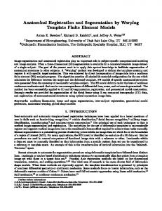
Figure 3. Range-sensing: (a) laser triangulation: (h) defocusing; (c) equipment Laser-based triangulation involves projecting a thin ray of laser light onto an object. capturing the reflected light by a charge-coupled device (CCD), and inferring depth from the pixel position of the reflected point and from the geometric relationship between the position of the laser source and the CCD. The relationship which summarizes the triangulation is illustrated on figure 3(a) and expressed as44:
dl p + 1 tan8
(4)
In equation (4), is the range value of the scene point. d is the width separating the laser source from the CCD oi>tieal (enter. / is the distance from the lens to the image plane, 8 is a fixed angle expressing the attitude of the laser source, and p is the pixel position of the reflected point. This relationship is characterized by a calibration procedure. after which each laser peak detected at pixel (i. J) on the CCD is interpreted as the (x, z) position of the point of tile scene illuniinated by the incident laser ray. Ordinarily, in order to get range information at regular samples of a surface, this ray would have to be swept along two axes normal to each other and spanning a plane which is aligned with a local plane tangent to the anatomical surface of interest. However, our sensor dispenses with one sweep axis by optically spreading the ray into a laser plane. The intersection of this plane with the imaged ()hlCCt instant aneouslv produces a 2D range-map of a 'slice" of the surface. which appears as a curve of 256 points, or laser profile, on the CCD . A 3D surface is then obtained by linearly sweeping the sensor, ideally in a direction normal to the laser plane. across the surface of interest. The coordinate y is given by the positioner. and the three coordinate axes form a normal basis. Defocusing exploits the Gaussian lens formula. 1/o+ 1// 1/f. to correlate the blurring which arises from small changes to either the object distance o or lens-image plane distance I, with the object distance itself (f is the focal length). In principle, the closer an object is to the lens, the greater the defocusing effect from a given incremental movement of the image plane.3° in our sensor. this technique is implemented by allowing the laser light to pass through two holes, at a predetermined distance d apart. rather than one. The CCD sees two laser profiles instead of one, and range is determined by measuring the space b (in each pixel column) between the two images b1 and b2 of a laser point, as illustrated in figure 3(b). according to the expression:
=
o.
1
+ b/(dl) '
(5)
where I and d are the lens-image plane and laser diode-optical center distances, as before. The range measurenients obtained by triangulation and by defocusing are combined by assigning weights to the two expressions for z given in expressions (4) and (5). with most (8O) of the weight given to former, because laser peak position varies much more than peak separation as a function of range. The pixel position p used for triangulation is taken as the average of the two detected laser peaks in each CCD column. Furthermore, the combination of the two techniques provides constraints for detecting peaks unambiguously in each column of the CCD.44 TL5,ser profiles are acquired at a 60 Hz rate: collecting a 256 x 256 range image. consisting of 256 profiles spanning the surface of interest, requires just over four seconds.
114
Finally, the sensor has a depth of field of 135 mm (from 108 mm to 243 mm), which for a 256-pixel CCD corresponds to roughly .5 mm pixel accuracy. The field of view at a typical range is around 10-12 cm (depending on the proximity of the sensor to the surface), which gives it a .4-.5 mm pixel accuracy width-wise. The sensor is linearly swept across the skin or cortical surface by a flexible low-cost commercial positioning system which possesses .02 mm repeatability and is capable of 150 mm travel at speeds up to 330 mm/sec. During this linear travel, our program acquires 256 laser profiles at a constant rate, when the positioner is known to move at a constant speed. The equal spacing of our samples, resulting from the CCD being regular (in the i-k pixel coordinates, not in x-z spatial coordinates) and from constant-rate acquisition along the y-axis, is exploited later on in the registration process. Both the sensor and the positioner are supplied with Windows-based software interfaces and dedicated control hardware. Both software interfaces support a standalone program calling vendor-supplied libraries. A picture of our range-sensing system appears in figure 3(c).
2.3. Surface displacement estimation We estimate cortical surface deformation by first establishing a baseline for this movement, then by registering the initial cortical range image with its homologue identified in the MRI volume, and finally by tracking non-rigid cortical surface motion between time t,- and time t,1 . The baseline for cortical movement must be implemented by a rigid registration of the range and MRI-based skin surfaces, which is not a trivial problem because an arbitrarily large transformation must be computed. This problem is generally approached by feature-based techniques in the literature,5 yet the surfaces involved are potentially featureless, particularly in the back of the head. For the time being, we work with a brain-shaped phantom which does not possess a skin or a bone layer, and obtain this movement baseline by manually providing a rough alignment (based on the four corners of the range image domain) between the initial range and MRI surfaces of this phantom, and by refining it with a rigid-body registration to initial range data. The rigid-body refinement, at to , and all subsequent non-rigid stages of cortical registration are implemented with an iterative closest point (ICP) technique.6'23
The justification for employing an ICP approach is that it provides a much denser displacement map than a feature-based technique. This density is important to best quantify non-rigid surface motion, which is fundamentally underdetermined. Moreover, although it is conceivable that the level-set framework could be used here, at the cost of replacing the initial MRI-based image function by one driven by the range image sequence, we prefer an approach which restricts the surface tracking to the domain of the range image. We thus defer the computation of the motion of the surface outside the range domain (i.e.: not visible through the craniotomy) to the FEM stage, which can estimate this motion in a manner which accounts for real (not virtual) material properties. This leaves us with an ICP-type technique, which is better-suited to non-rigid motion estimation than a feature-based approach, and to tracking a range image (which does not require prior segmentation within a volume) , than an active surface model.5 Its main
drawback is that it requires a rough initial alignment, but this requirement is met by the initial rigid registration carried out to determine the baseline for cortical movement.
Our iterative registration technique bears some comparison to that of Lavallée and Szeliski,23'4° in that a distance map is precomputed for the MRI volume from the identified cortical surface, thereby accelerating the computation of distances between closest-point pairs, rather than imposing an expensive search for them. Lavallée represents the volume containing the surface by an octree structure, then determines the closest surface point to each corner of each cube in this representation, computes the resulting distance to it, and finally interpolates with trilinear splines the resulting sparse distance map. When a second (in our case, range) surface falls within the mapped volume, each point on it inherits a distance value to its closest homolog of the first surface. Lavallée then seeks the transformation which best accounts for these distances, or which best registers the second surface to the first, in a weighted least squares sense. Because this method produces only a distance map, but does not provide information about which particular point is closest, it must resort to a search method, such as Levenberg-Marquardt, to determine the optimal transformation. In contrast, closed-form methods for computing transformation parameters, such as Arun's SVD technique,3 either Horn's18 or Faugeras & Hebert's'5 quaternion method, or Walker's dual quaternion45 algorithm, all require explicit point-pairs, not distances between them. As emphasized in § 2.1, we make use of the fast marching level-set method to produce a dense map of both closest point labels and the distances to them, doing away with a search for closest points as well as producing explicit point pairs which can take advantage of closed-form transformation algorithms, thereby making each iteration of our ICP technique essentially instantaneous. We currently use the SVD
115
technique to compute the rigid transformation between the two sets of points. Successive rigid-body iterations are handled by multiplying homogeneous transform matrices.13 The non-rigid registration stage uses the same ICP matching technique to produce a smoothed displacement vector function either from the updated MRI/CT cortical surface at t (at the cost of recomputing the distance map by fast marching level sets) or from the preoperative cortical surface to the points of the range image at t+i . Starting from the surface at t may appear slightly more expensive computationally but makes better use of our temporal resolution in estimating non-rigid motion. We restrict our non-rigid registration to the domain of the range image for now. The expression of the deformation over a 2D domain is a consequence of our explicit displacement information being available only on an open surface, below and outside of which we defer to a realistically valued finite-element model to estimate volumetric movement. Furthermore, we exploit the regularity of the range domain by using extremely efficient recursive smoothing splines42'43 to smooth the displacement function. The justification for emphasizing computational efficiency here is two-pronged: clinical acceptability and the inherent temporal underdetermination in estimating non-rigid motion. Clinical acceptability hinges on allowing the surgeon to easily deploy the system, get the surface displacement quickly, use this surface information with efficient FEM schemes4 to estimate volumetric displacement, and proceed with the surgery. The issue of underdeterminacy implies that it makes sense to enable the acquisition of a large number of displacement maps over time if needed, just as it does to use dense point displacement information to characterize non-rigid motion between any two successive instants. Our efficient implementation of surface splines draws on the work of Unser et al,42'43 which expresses the fitting of interpolating, smoothing or approximating splines as a sequence of filtering stages, all of which can be implemented as recursive filters, provided that the data are sampled at regular positions. As mentioned earlier, this is the case for the range surface points, at least in the space (i, i) spanned by CCD pixel coordinates i and image acquisition points j along the positioner axis (the smoothed displacement over (x, y) can then be obtained by a simple transformation). We adopt a smoothing spline approach, whose first stage is a convolution with a smoothing kernel
S(Z) = 1/(B(Z)+A(_Z+2_Z-1))
(6)
where Br(Z) s the indirect B-spline transform given by Unser,42 ii is the order of the spline fitting and A is the regularization parameter of the smoothing. This stage produces B-spline coefficients and is followed by a convolution
with the indirect transform Br(Z) to yield the smoothed output. The filters can simply be cascaded to implement smoothing in 2D. We adopt a first-order fit to limit overshoots due to a higher-order continuity constraint, near the boundary of the craneotomy, outside of which the displacement should be null after rigid registration. These operations in Z-space translate to local operations in 1D involving immediately neighbouring range image points, independently of the value of the smoothing parameter A. Just prior to each spline fitting operation, in order to define a displacement vector at image coordinates where range information is lacking, due to possible occlusion or low signal value, an average of valid neighbouring displacement vectors, weighted according to the proximity of the corresponding range point, is propagated and iteratively refined. Lastly, in order to make the non-rigid motion estimation well-behaved, the smoothing parameter A is initially set very high, and is gradually lowered as the process iterates, progressively resolving finer-level motion detail. Just as for the rigid ICP stage, each iteration of the non-rigid surface motion estimation is essentially instantaneous.
2.4. Elastic brain phantom For the purpose of reproducing non-rigid cortical movement, we have implemented a brain-shaped phantom with elastic material properties. We use a jello mold in the shape of the brain (obtained from the Anatomical Products Online website2), into which we pour PolyVinyl Alcohol Cryogel (PVA-C), as illustrated in figure 4(a). The latter is a relatively viscous liquid, which upon freezing and thawing, becomes an elastic solid'0 as shown in figure 4(b). Furthermore, PVA-C can sustain several freeze-thaw cycles to acquire more rigidity, and the PVA concentration can also be manipulated to that effect, producing a Young's modulus E in the .1 to .7 MPa spectrum.38 This is comparable to values published in the literature for gray and white matter material properties. Note: Z here relates to the Z-transform, not to be confused with the depth axis of the range-sensor. Zhou,49 for example, lists bulk moduli K of .219 GPa and .349 GPa, for gray and white matter, as well as a Poisson's ratio v of .4996 for each. These values translate to values of E of .525 MPa and .837 MPa respectively, based on the formula K = E/[3(1 — 2v)] for isotropically elastic material.25 The values found elsewhere in the literature are closer to the lower end of the PVA-C spectrum.28
116
Figure 4. Elastic PVA-C brain phantom: (a) hquid stage (h) final result after freezing and thawing. This phantom rests on a support plate of plexiglass (usable within an MR scanner), and features a moving assembly consisting of a small disk and rod, also of plexiglass. imbedded within the elastic material, as well as sonic glass beads used to validate the surface displaceinent/FEM approach to volumetric motion estimation. The other
end of the rod (outside the elastic material) is attached to an external plate which rests on the opposite side of the support plate. The position of the moving assembly can be modified by means of some set screws pushing the external plate away from the support plate. thus drawing the embedded disk toward the support plate and triggering a compression of the elastic material.
Finally, because both the liquid and solid forms of P\A-C are translucent, and as this characteristic has an adverse impact on the range-sensor (leading to multiple reflections of each laser plane), we use spray-paint to render he curt ical surface of our phantom opaque. Translucency is obviously not a characteristic shared by the human brain, arid we've established that our sensor can image brain tissue without any problems or pre-treatment. We are investigating other means of achieving opacity for our phantom. including a suspension of nylon or graphite particles within the PVA.
3. RESULTS AND DISCUSSION Our segmentation implementation produces the expected results, as apparent with the scan of our brain phantom in figure 2. So far, we report no new findings in this area, although we do anticipate further research on segmentation, part icularlv in a manner which exploits prior anatomical knowledge. Our main justification for using a level-set techmnque is that it is highly adaptive to different topologies and tolerant to user-initialization, which make it suitable for identifying all the anatomical surfaces which we want to either subsequently register or characterize in terms of circumscribed tissue type. One of the niain contributions of this paper. namely that the level-set framework leads to a very efficient iterative surface registration. is simply a fortuitous by-product of our segmentation design choice. Our tests indicate that our iniplementation of an iterative closest point registration also produces anticipated results, as shown in figures 5 and 6 for rigid and non-rigid registration respectively. The algorithm, given a good starting point, does indeed converge to a very good pose estimation. The results of figure 5 are based on an initial aligmimnent carried out by choosing four points on the level-set surface which roughly correspond to the corners of the range image. to which an arbitrary vertical distance of 15 pixels, or roughly 13.5mm was added. The gradual reduction in RMS point-pair distance, whose rate of convergence levels off somewhat after 4-5 iterations, is comparable to other ICP methods (see the results in Zhang,48 for example).
In order to assess non-rigid surface tracking, we turn the set screws under the support plate of our elastic phantom, triggering a deformation of up to 15mm at the top. and image the cortical surface with our range-sensor, while maintaining the support plate fixed with respect to the range-sensor/positioner reference (see figure 4(b)). We then compare the results of a strictly rigid transformation computation with a sequence of rigid and non-rigid ICP registrations. Each option uses the same rough initial alignment based on the corners of the range domain. This comparison is currently based on visual inspection of how the original MEl level-set surface, subject to the inverse of the range-to-NIRI transformation, aligns with the range data of the deformed cortical surface. and on the two plots of the RNIS distance between point-pairs against iteration number. The abrupt improvement of RMS distance
117
4
2.
4'!
S.,-
Figure 5. Typical rigal regist ration results: (a) transformed range iniage overlaid oii NIB I level—set siiriace ( both deciiiiated by a factor of 2 fir readability) in MRI space: (1)) single range profile (j = 192 or q = 79.592) wit Ii projections of closest NIRI points on y 79.592 plane. in range space: (c) R\IS point—pair distance plotted against ICP iterat ion number.
.4
—242
24P
-260
2C -60
120
4.-
4" y,mml • rnnfle space,
ylrrml 1411110 Sp44p
C 60
, 1cm Cr311311 Spli-,
_r'r
suflr,1,Craflqe Space 1
2'S
Figure 6. Typical non—rigid registration results: (a) NIRI level—set surface rigidly registered to the range image of the (leforliled phantom. in range space (both decimated by a factor of 2) (b) NIRI level—set surface non—rigidly registered t t lie range image of the deformed pliantoni (both decimated by a factor of 2): ( c ) slice t brougli (a). at
=
79.592: (d) slice through (b ) . at
=
79.592: (e ) evolution of RNIS point —pair (list alice with ICP iteration.
on the second curve indicates the initiation of the non—rigid stage. with an earlier rigid stage ternhinat ion than time rigid—body stage illustrated by the first curve. Each SVD and recursive splines iteration is indeed computed in less than a second (closest—point pairs are merely looked up), although the iterative filling—in of missing range data can take inure than a second, depending on the accuracy threshold used for stopping this iteration. The RMS point-pair distance which appears in figures 5 and 6 may in fact overestunate the registration error
118
between the two surfaces, due to the range data being much denser than the overlapping MRI-voxels which constitute the homologous patch of the level-set surface (65536 vs. 5782 points). In other words, because the ICP range-to-level set matches can be many-to-one, the point-pair distance has a large component which lies in the plane normal to the vector along the shortest path between the two surfaces which emanates from each level-set surface voxel. If we were to measure the error between one-to-one matches (between each matched level-set surface voxel and the closest of its range image matches, or between each level-set surface voxel and its projection on the range image), a much reduced registration error would result. Furthermore, if the displacement vectors between the original (manyto-one) closest point pairs are used to determine the non-rigid spline-based transformation, we find that they distort the displacement map by inflating the components (essentially along x and y) normal to the shortest path at each point between the two surfaces. We obtain better results by considering only the displacements of mutually closest (i.e.: one-to-one) pairs, which can be determined fairly easily from the original set of point pairs, and iteratively propagating this information everywhere else. Another approach worth investigating in the future is to use all pointpairs to determine the z component of the displacement vector, and only the mutually closest to compute the x and y components, which would then be propagated everywhere. It can be said that an ICP-type method is sensitive to local minima and therefore dependent on a good starting
point.48 This issue leaves us with two options which warrant further investigation in the future. The first is to ensure that a good starting point exists by applying the rigid skin registration technique to the cortical surface as well, albeit with a lesser search space used with the latter than the former. As alluded to previously, this problem is difficult because of the relatively featureless areas which are likely to appear, particularly on skin, and the arbitrarily
large transformation which must be computed. However, a number of techniques may be adapted to our needs, such as Johnson & Hebert's spin-image correlation'9 and the eigenfeature characterization currently used for face recognition4' and intensity image retrieval,39 neither of which compute features based on surface curvature. The second option is to make our iterative registration more tolerant of initial misalignment by incorporating local surface shape information in a manner related to the method of Feidmar & Ayache,16 which iteratively matches closest feature vectors comprised of position and surface shape/orientation data. This option hinges on local cortical surface shape being at least as discriminant as the z-component of pixel position, on temporal changes in cortical
surface shape not being too significant and on resection areas being identified, possibly automatically. It is true that the multidimensionality of the Feldmar approach doesn't carry over well to a level-set framework, which adds one more dimension still. Even a set of surface points characterized in terms of 3D position plus just one shape parameter, say Gaussian curvature K, would lead to a problem which is 5D, and therefore fairly daunting in a level-set framework. The high dimensionality issue could be alleviated by computing a second 4D distance map after the skin-based rigid alignment (in just a few minutes, with the fast marching technique, while the craneotomy takes place), which would imbed the subpatch of interest characterized only in terms of (x, y, K). Our iterative scheme could then alternate between two sets of closest-point pairs: those which are strictly position-based and those which account for surface shape. A more thorough validation will dictate which of these two options, initial non-iterative cortical registration or shape-based feature vector matching, we will adopt.
4. CONCLUSION This paper proposes a novel means of estimating intrasurgical deformations, based on level-set segmentation, rangesensing of the skin and cortex, fast rigid and non-rigid surface registration, and finite-element based estimation of volumetric displacement. We have emphasized some of the machine vision issues in this approach, in particular how the level-set framework can be exploited to yield computational speedups in the surface registration. The use of recursive splines is also a factor in our algorithmic efficiency. We have also presented a new brain-shaped elastic phantom with which non-rigid cortical movement can be enacted and our method can be validated.
5. ACKNOWLEDGEMENTS The authors wish to thank Kaleem Siddiqi, Ron Kimmel, Frank Ferrie and Ken Chu for their help with this research.
This work was supported by the National Science and Engineering Research Council of Canada NSERC grant 0GP0155058, and the Medical Resarch Council of Canada MRC grant MT11540.
119
REFERENCES 1. D. Adelsteinsson & J.A. Sethian, A Fast Level Set Method for Propagating Interfaces, J. Computational Physics, No. 118, pp. 269-277, 1995. 2. Anatomical Products Online website, www.anatomical. com/catalogs/product/21 01 3brainmold.html, 1998.
3. K.S. Arun, T.S. Huang & S.D. Blostein, Least-squares Fitting of Two 3-D Point Sets, IEEE Trans. Pattern Analysis ei Machine Intelligence, Vol. 9, No. 5, pp. 698-700, May 1987. 4. 0. Astley & V. Hayward, Real-Time Finite-Elements Simulation of General Visco-elastic Materials for Haptic Presentation, IROS '97, IEEE/RJS mt. Conference on Intelligent Robots and Systems, Sept. 1997. 5. M.A. Audette, F.P. Ferrie & T.M. Peters, An Algorithmic Overview of Surface Registration Techniques for Medical Imaging, Medical Image Analysis, submitted. 6. P.J. Besl & N.D. McKay, A Method for Registration of 3-D Shapes, IEEE Trans. Pattern Analysis 4 Machine Intelligence, Vol.14, No.2, pp. 239-256, 1992. 7. V. Caselles et al., A Geometric Model for Active Contours in Image Processing, Numerische Mathematik, No. 66, 1993. 8. V. Caselles, R. Kimmel & G. Sapiro, Geodesic Active Contours, Proc. IEEE mt. Conf. Computer Vision, pp. 694-699, 1995.
9. V. Caselles et al., Minimal Surfaces: a Three Dimensional Segmentation Approach, Technion EE Pub. No. 973, 1995.
10. K.C. Chu & B.K. Rutt, Polyvinyl Alcohol Cryogel: An Ideal Phantom Material for MR Studies of Arterial Flow and Elasticity, Magnetic Resonance in Medicine, No. 37, pp. 314-319, 1997. 11. L.D. Cohen, On Active Contour Models and Balloons, CVGIP: Image Under., Vol. 53, No. 2, pp. 211-218, 1991. 12. R.M. Comeau, A. Fenster & T.M. Peters, Intra-operative Ultrasound Imaging in Image-Guided Neurosurgery, Radiographics, No. 18, pp. 1019-1027, 1998. 13. J.J. Craig, J.J., Introduction to Robotics: Mechanics and Control, Addison-Wesley, 1989. 14. H.R. Everett, Sensors for Mobile Robots : Theory and Application, A.K. Peters, 1995. 15. O.D. Faugeras & M. Hebert, The Representation, Recognition, and Locating of 3-D Objects, mt. J. Robotics Research, Vol.5, No.3, pp. 27-52, Fall 1986. 16. J. Feidmar & N. Ayache, Rigid and Affine Registration of Free-Form Surfaces, using Differential Properties, Proc. Euro. Conf. Comp. Vision, pp.397-406, 1994. 17. V. Hayward et al., Freedom-7: A High Fidelity Seven Axis Haptic Device With Application To Surgical Training, ISER-6 International Symposium on Experimental Robotics, June 1997. 18. B.K.P. Horn, Closed-form Solution of Absolute Orientation Using Unit Quaternions, J. Optical Society ofAmerica A, Vol. 4, No. 4, pp. 629-642, April 1987. 19. A.E. Johnson & M. Hebert, Surface Registration by Matching Oriented Points, mt. Conf. Recent Advances in 3-D Digital Imaging and Modeling, 1997. 20. B.B. Kimia & K. Siddiqi, Geometric Heat Equation and Nonlinear Diffusion of Shapes and Images, Computer Vision and Image Understanding, Vol. 64, No. 3, pp. 305-322, Nov. 1996. 21. R. Kimmel, N. Kiryati, and A.M. Bruckstein. Sub-pixel Distance Maps and Weighted Distance Transforms, J. Mathematical Imaging and Vision, No. 6, pp. 223-233, 1996. 22. Laser Institute of America Corporate Membership Directory, www.laserinstitute.org/corporate/industsys.html, 1998.
23. S. Lavallée & R. Szeliski, Recovering the Position and Orientation of Free-form Objects from Image Contours Using 3D Distance Maps, IEEE Trans. Pattern Analysis Machine Intelligence, Vol. 17, no. 4, pp. 378-390, 1995.
24. R.J. Leveque, Numerical Methods for Conservation Laws, 2nd ed., Birkhäuser Verlag, 1992. 25. L.E. Malvern, Introduction to the Mechanics of a Continuous Medium, Prentice-Hall, 1969. 26. R. Malladi, J.A. Sethian & B.C Vemuri, Shape Modeling with Front Propagation: A Level Set Approach, IEEE Trans. Pattern Analysis 4 Machine Intelligence, Vol. 17, No. 2, Feb. 1995. 27. C.R. Maurer et al., Measurement of Intraoperative Brain Deformation Using a 1.5 Tesla Interventional MR System: Preliminary Results, IEEE Trans. Medical Imaging, Vol. 17, No. 5, pp. 817-825, Oct. 1998. 28. M. I. Miga et al., A 3D Brain Deformation Model Experiencing Comparable Surgical Loads, Proc. 19th Tnt. Conf. IEEE EMBS, pp. 773-776, 1997.
120
6
0
'1UOJ,\J 3J oqo!iou 2? JI-T
O NS
T
M
'p[ '
'iuisiqxoj
'SmJ :dJDAQ 5nvti '5uzpuvsJdpufl1°A °N
A ''IN odq ''N dd 'is- rv
'
2?
°M
uopJ U1Sfl A!SiflZJ :uuITJ uooi1ddy o iuuizg
UIOIJ 'SflDO
uf T66T
dd 'L-9L
$uiA4j
uJvçJ z$f17vuy
duzzpvlJ 'ud6z/lduI i°A '91
1766T IOJpg 2?
f 'JS3 I'PA W°U WODJ!A '1oIrn1rs lppV dfln?uI fluzimthuo pun pSy-TIO s iqs yç 'uqog suoj U!??dOid qI uopudo-oJnAin3:pdS SUITpUOJ ps U -UOTTUrH !qoc 'suo!Inullod •f ivuowndoo ''dZ9fiYcf °M '6L dd '6fT S6T J ')p!ApoS Si1LpiLOfi7y ui pit: 'P 'iTSOM-UOSippV 66T VT '''IS SJ N'JAI TAI poij iOJ icTIDuoouoJ/\IUiuApv 's:uoi pv •idS 'vsn 1°A '6 dd '6T-T6T qd 966T LtId
'UruIflN
rJrJ
-uozudcudluI '96IVODIJ2V dd 'L16-0T6 66T
'
•: IN -'!S 2' F\IJ 'siaO sfl jo ui: oquuojo pn sTBpoJ/\ UOIZITnSTA P -rn?nb uoqop jo p?q3 OflSSJ 'SdIc1 1°A 'T °N d 'TTT A1nç L66T 9 o '1'is u JaUOdS 2' •f 'Ifl?DUflJ "!H JNS UHPOF\I fl "! 'LtO1flSO1flON lndzp dflvtuI 5uzmthuo pun PV°D -uoiuaJduI '96IVDDIP1[ dd '6f'9-Tf'9 66T L qd 'tfl?or-S •j•y 'opp •TcE 'su!TIoD •ci '%puoID •y 'SUA PIIL 'S0d pomo:ny sTw -uI pui OAqZYiUI JUOiSUOUIi-Oiqj
'
1OJ
'UOPOSO3J 7vdzpapij
1OJ
UOii
'Liinsoi
¶I
'
up!nD O 66T dd 'O9L9
UOiZTIflStA SOOJ iOJ UTUU?Td pU
Sun4]
/vpa 'ôuzflvuii 1°A 'LT °N
JO WUO!PUfltT
-nN
•: •N 'A:nnS 'zpv/vduowsnzL-nmm 6661 6 TG °"S ? 'UM USfl •suv4L uivj $if1/vuy M SOiflOJUi ioJ owI 'IAJT aunpn 'du6illuI I°A 'T °N dd '9-T •:rty 966T }J flSTOZ S '0TTAT"P-PVJN Ui T'""V SZYJifl SUOtWJOJOJ TTS1 'souqd-Jcp ui •f Ld1rtdmo3 'uoz$z4 i°A 0 dd '9T-TLT 9661 P!ThU0N P1L V 'PUIUd SD13JUOEI ioJ 'Uo!!uo3o3-J •f 'aUdiOJUdN 1°A ': °N 'T dd 9-IL T66T j, 'isuç y 'qnoipJy 2' 'UOp 1d -j 'ciooq ¶3j $uai /VU5i' '°41 i°A I%u!S :uissoij 'TT °N 'g dd '-T qj 66T •f7 •J/I 'isuu •y 'qnoipy 1d II UPU:JE uso pu 'suo!!JddV 'up ou!IdS-H [?Ui :uissooi 'uvJ1 jvufiig HOJc[ 1°A 'TT °N 'g dd qd 66T jj u!A 'Uo!?JOdio3 ua.fj 'lv1uvpv L66T MJAI rj OT
'
T
OT
'ST
TT JAI
•I:'I
'
TTA1
afli1iUflOQ
OUTTdS-H
•JAI
'
'-i
VH 'ZIOA UWS[ (J- UOOJ '°TTM :jIDflQ d5vui 'ôuzpuvsidpufl i°A 'c °N dd 'L9f:-: T66T
TZZOA 'c ° 'T v '5uôvj i°A '9T •°N
' x uo o '•j uoruui V
Ufl rru
'suo!TLIo?nb
uoqum o ipii 'smj sun 'sns uj uoqsj
oju
ioj s'uvij ixnppij 'A1omi dd '60g-66T idy L66T LT U1 svioiiioinsoj,\ jo ot[ xo:io3 moij cii: TJ,'I aôwiq ôuznctu,o pun -UOiZU?flJ3ZU '86JVDOIPV dd 'O-6T 66T z A14J UiOd ioj jo mioj-oi pu •f duo 'uozA 1°A 'T °N dd 'g2T6TT 1'661 6T 3 'noq W1 'HITN 1V V IPOJAI uucImo3 pdwj sosuodsoj jo oq snouowo11 pu 9T
'
SflOUOOfflOqUJ UmUH
''N
N
'uiH f1dwoS Jo
's'Jdauiflur
uj LioctaL ''1L96# 66T
1
1?