Library-Based Design and Consistency Checking of System-Level Industrial Test Cases Oliver Niese1 , Bernhard Steffen2 , Tiziana Margaria1 , Andreas Hagerer1 , Georg Brune3 , and Hans-Dieter Ide3 1
2
METAFrame Technologies GmbH, Dortmund, Germany {ONiese, TMargaria, AHagerer}@METAFrame.de Chair of Programming Systems, University of Dortmund, Germany
[email protected] 3 Siemens AG, Witten {Georg.Brune, Hans-Dieter.Ide}@wit.siemens.de
Abstract. In this paper we present a new coarse grain approach to automated integrated (functional) testing, which combines three paradigms: library-based test design, meaning construction of test graphs by combination of test case components on a coarse granular level, incremental formalization, through successive enrichment of a special-purpose environment for application-specific test development and execution, and library-based consistency checking, allowing continuous verification of application- and aspect-specific properties by means of model checking. These features and their impact for the test process and the test engineers are illustrated along an industrial application: an automated integrated testing environment for CTI-Systems.
1
Introduction
The increasing complexity of today’s testing scenarios for telephony systems demands for an integrated, open and flexible approach to support the management of the overall test process, i.e. specification of tests, execution of tests and analysis of test results. Furthermore, systems under test (SUT) become composite (e.g. including Computer Telephony Integrated (CTI) platform aspects), embedded (due to hardware/software codesign practices), reactive, and run on distributed architectures (e.g. client/server architectures). As a consequence, it becomes increasingly unrealistic to restrict the consideration of the testing activities to single units of the systems, since complex subsystems affect each other and require scalable, integrated test methodologies. The requirements discussed in this paper exceed the capabilities of today’s testing tools. To our knowledge there exist neither commercial nor academic tools providing comprehensive support for the whole system-level test process. In particular, most research on test automation for telecommunication systems concentrates on the generation of test cases and test suites on the basis of a formal model of the system: academic tools, like TORX [22], TGV [2], Autolink [13], and commercial ones like Telelogic Tau [21] presuppose the existence of H. Hussmann (Ed.): FASE 2001, LNCS 2029, pp. 233–248, 2001. c Springer-Verlag Berlin Heidelberg 2001
234
O. Niese et al.
fine-granular system models in terms of either automata or SDL descriptions, and aim at supporting the generation of corresponding test cases and test suites. This approach failed to enter practice in the scenario we are considering here, because it did not fit the current test design practice, in particular because there does not exist any fine granular formal model of the involved systems. Therefore in our approach we aim at a formal methods-controlled, component-based test design on top of a library of elementary but intuitively understandable test case fragments. This establishes a coarse-granular ‘meta-level’ on which – – – –
test engineers are used to think, test cases and test suites can be easily composed, test scenarios can be configured and initialized, critical consistency requirements including version compatibility and frame conditions for executability are easily formulated (see Section 5), and – consistency is fully automatically enforced via model checking and error diagnosis. Already after a few months of cooperation this coarse-granular test management support was successfully put into practice, drastically strengthening the pre-existing test environment. We are not aware of any other test environment systematically addressing the needs of coordinating the highly heterogeneous test process, let alone on the basis of formal methods. The paper is organized as follows: Sect. 2 describes our application domain, system level testing of telephony systems, presents a concrete scenario, and introduces the requirements to the corresponding integrated testing environment. Sect. 3 presents our test coordinator tool, Sect. 4 describes the formal foundations of its design and analysis core, Sect. 5 shows the aspect-oriented character of the automated verification by discussing concrete classes of constraints, and Sect. 6 discusses the impact of the new environment on the test development practice. Finally Sect. 7 draws our conclusions.
2
System-Level Testing of Telephony Systems
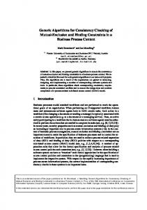
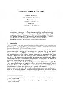
As a typical example of an integrated CTI platform, Fig. 1 shows a midrange telephone switch and its environment. The switch is connected to the ISDN telephone network or, more generally, to the public service telephone network (PSTN), and acts as a “normal” telephone switch to the phones. Additionally, it communicates directly via a LAN or indirectly via an application server with CTI applications that are executed on PCs. Like the phones, CTI applications are active components: they may stimulate the switch (e.g. initiate calls), and they react to stimuli sent by the switch (e.g. notify incoming calls). In a system level test it is therefore necessary to investigate the interaction between such subsystems. Typically, each participating subsystem requires an individual test tool (see Sect. 3). Thus in order to test systems composed of several independent subsystems that communicate with each other, one must be able to coordinate a
Library-Based Design and Consistency Checking
235
Fig. 1. Example of an Integrated CTI Platform
heterogeneous set of test tools in a context of heterogenous platforms. This task exceeds the capabilities of today’s commercial test management tools, which typically cover the needs of specific subsystems and of their immediate periphery. The remainder of this section explains and structures the corresponding central requirements for practice-oriented test management along the typical corresponding lifecycle: test case design, test organization, and test coordination. 2.1
Test Design Requirements
The design of test cases, i.e., specifying which control or inspection activities must be performed on the SUT and in which order, should neither require programming skills nor any knowledge of how to apply/use a specific test tool. In particular, concrete requirements concern the following areas: Definition: Test cases should be graphically specifiable at the level of SUTusage. A generalization by means of parameters should be supported. Reuse: A macro mechanism should support the reuse of (partial) test cases. This automatically supports a hierarchical design style. Validation: Consistency checks of tests cases at design time should guide the designer towards building (only) plausibile test cases. Variation: Rule-based controlled as well as randomized parameter variation should enhance the expressiveness of the test results. 2.2
Test Organization Requirements
The central organizational aspects of the test process are: Version control: (at the physical persistency level) Beside the test cases themselves, many other files referenced and used in test cases have to be organized, e.g. configuration files and test documentation. All these files evolve
236
O. Niese et al.
throughout the test process. Therefore, it is important to capture the history of changes and the dependencies between versions. Configuration management: It is mandatory, especially when considering integrated tests, that the SUT is in a well defined state before a test run is started. This is a non-trivial task because we treat complex systems, where the initialization is a distributed problem, and the initialization of one component typically affects the state of the others. Structuring of tests: Tests must be structured to – provide a simple mechanism to build test suites from test cases according to a variety of criteria, e.g. regression test or feature test for a certain test scenario. – eliminate redundant test cases. This may dramatically reduce the whole test execution time, which is important for the scenario of Fig. 1, where new versions of the switch software must continuously be validated against the CTI applications. 2.3
Test Coordination Requirements
The whole test execution process must be supported, including: Initialization: SUT components and test tools must be set into a well-defined starting state. Fast reinitialisation in case of repetition of a test case must be possible. Execution: Distributed executed test tools of different abilities and different interconnection variants must be controlled in a way that emphasizes on the aspects control of tool activities and determination of state and state changes of SUT components for verification purposes. Reactions of SUT components on stimuli must be retrieved and evaluated. The evaluation results shall control succeeding test case steps. Timing constraints must be taken into account when stimulating a SUT component. Reporting: Reporting shall record a test run and shall facilitate documentation and tracking of defects by providing sufficent details. A characterization of the SUT, i.e., versions of SUT components and of test tools, must be documented. Result and data of each step of the test case must be logged. The status of a test run must be summarized. The next section describes how we attacked the requirements according to the test coordination aspect: design and execution of functional tests. Other aspects, like a sophisticated configuration management or the structuring of tests, are left to a subsequent phase.
3
The Test Coordinator
The realization of an adequate management layer for an automated test environment was attacked according to pragmatic criteria, of vital importance in an
Library-Based Design and Consistency Checking
237
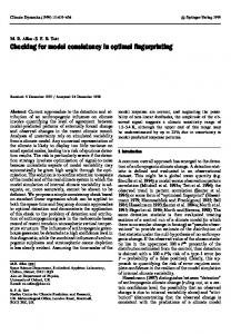
Fig. 2. Architectural Overview of the Test Environment
industrial development environment: first of all, the test environment should offer a viable execution environment (Test Coordination Requirements), then scale up to the required complexity (Test Organization Requirements), and also ease the test design phase (Test Design Requirements). Accordingly, we built on an existing general purpose environment for the management of complex workflows, (METAFrame Technologies’ Agent Building Center (ABC)) [18], which already encompasses most of the above mentioned features in an application-independent way. This way we were able to demonstrate in a short time the practical satisfiability of the kernel requirements concerning test coordination and test organization. In fact the currently available Test Coordinator (Fig. 2), which constitutes the test management layer of our environment, includes a specialization of the ABC for this application domain, i.e. system level testing of telephony systems. Meanwhile, the test management has already proved to be capable of coordinating the different control and inspection activities of integrated system-level tests. Figure 2 shows the general architecture of the Test Coordinator. The SUT is composed of several subsystems, e.g. a telephone switch in cooperation with a
238
O. Niese et al.
CTI application. Each subsystem is controlled via its own test tools1 . The test 1 ) 2 as well as to some internal ones tools have access to external interfaces ( , 3 They are steered by the Test Coordinator. For more details concerning the ( ). integration process of the test tools see [8]. Up to now, the effort in the project was mainly devoted to the support of test design and to the handling of advanced coordination and organization requirements. 3.1
ABC’s Enabling Characteristics
The following characteristics of the ABC proved to be of major importance, due to the heterogeneous composition of the team (researchers, developers, and prospective industrial users coming from different groups within Siemens, with different focus on the project). Behaviour-Oriented Development: In general, application development in the ABC, which goes far beyond the domain of CTI applications [18,17], consists of behaviour-oriented combination of building blocks on a coarse granular level. Building blocks are identified on a functional basis, understandable to application experts, and usually encompass a number of ‘classical’ programming units (be they procedures, classes, modules, or functions). They are organized in application-specific collections (palettes). In contrast to (other) componentbased approaches, e.g., for object-oriented program development, ABC focusses on the dynamic behaviour: (complex) functionalities are graphically stuck together to yield flow graph-like structures embodying the application behaviour in terms of control. This graph structure is independent of the paradigm of the underlying programming language. In particular, we view this flow-graph structure as a control-oriented coordination layer on top of data-oriented communication mechanisms enforced, e.g., via RMI, CORBA or (D)COM. Concretely, the test management layer communicates with individual test tools by means of CORBA [10]. Accordingly, the purely graphical combination of building blocks’ behaviours happens at a more abstract level. Incremental Formalization: The successive enrichment of the application-specific development environment is two-dimensional. Beside the library of applicationspecific building blocks, which dynamically grows whenever new functionalities are made available, ABC supports the dynamic growth of a hierarchically organized library of constraints, controlling and governing the adequate use of these building blocks within application programs. This library is intended to grow with the experience gained while using the environment, e.g., detected errors, strengthened policies, and new building blocks may directly impose the addition of constraints. It is the possible looseness of these constraints which makes the 1
Test tools can be e.g. proprietary hardware tracer for testing the switch or GUI test tools such as Rational SQA Robot [12] or Mercury Winrunner [7] for the test of applications.
Library-Based Design and Consistency Checking
239
constraints highly reusable and intuitively understandable. Here we consciously privilege understandability and practicality of the specification mechanisms over their completeness. Library-Based Consistency Checking: Throughout the behaviour-oriented development process, ABC offers access to mechanisms for the verification of libraries of constraints via model checking. The model checker individually checks hundreds of typically very small and application- and purpose-specific constraints over the flow graph structure. This allows concise and comprehensible diagnostic information in the case of a constraint violation, in particular as the information is given at the application rather than at the programming level. Taken together, these characteristics of the basic tool were actually the real enablers for the project results, in particular, as they provided a means to seamlessly coordinate the cooperation between ABC team, CTI expert, test designers, and test engineers.
4
Domain Modelling
This section summarizes the effort for instantiating the ABC as required for the CTI application. This mainly consists of the design of some application-specific building blocks, and the formulation of the frame conditions which must be enforced during test case design and test suite design. 4.1
Test Building Blocks
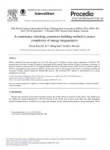
The ABC team, the CTI experts and the test designers define and also classify the building blocks occurring in the testing experiments, typically according to technical criteria like version or specific hardware or software requirements, origin (where they were developed) and, here, most importantly, according to their intent for the specific application area. The resulting classification scheme is a simplified version of the taxonomies used in [6] and [17]. At this stage, the building blocks occurring in the test cases are organized in palettes, accessible from the Test Coordinator’s GUI (see Fig.3, left), which are the basis for the test designers to graphically construct test cases by drag-and-drop. The test case design is completed by – connecting the test blocks by edges, and – configuring the internal parameters. The resulting test graphs are directly executable for test purposes, and, at the same time, they constitute the models for our verification machinery by means of model checking. Figure 3 shows a typical test graph for illustration. The palettes are thus central to build the models, and they constitute a vocabulary for the constraint definition in terms of modal formulas. Typically, the design of the classification scheme and of the constraints goes hand in hand with the definition of aspect-specific views and filters: both are mutually supportive means to an application specific structuring of the design process.
240
O. Niese et al.
Fig. 3. A Test Graph and the Test Block Palettes
4.2
Models and Constraints
Formally, test graphs are modelled as flow graphs (see Fig. 3), whose nodes represent test blocks governing the stimulation of the SUT, and whose edges represent branching conditions steering the flow of control. Definition 1 (Test Model). A test model is defined as a quadruple (S, Act, →, s0 ) where – – – –
S is the set of available test blocks, Act is the set of possible branching conditions, → ⊆ S × Act × S is a set of transitions, s0 is the uniquely determined initial test block.
In ABC test models are subject to local and global constraints which, in conjunction, offer a means to identify ‘critical’ patterns in the test graph already
Library-Based Design and Consistency Checking
241
during the early design phase. The classification of constraints into local and global is important, since each kind requires a specific treatment. The on-line verification during the design of a new test, however, captures both kinds of constraints. Local Constraints. Local constraints specify single test blocks in the context of their immediate neighbours: they capture a test block’s branching potential as well as its admissible subsequent parameterization. Their correctness is checked by means of specific algorithms, which can be activated at need. The verification of local constraints is invoked automatically during the verification process of global properties. Global Constraints: The Temporal Aspect. Global constraints allow users to specify causality, eventuality and other relationships between test blocks, which may be necessary in order to guarantee frame conditions for e.g., executability and version compatibility. A test property is global if it does not only involve the immediate neighbourhood of a test block in the test model2 , but also relations between test blocks which may be arbitrarily distant and separated by arbitrarily heterogeneous submodels (see Section 5 for concrete examples). The treatment of global properties is required in order to capture the essence of the expertise of designers about do’s and don’ts of test creation, e.g. which test blocks are incompatible, or which can or cannot occur before/after some other test blocks. Such properties are rarely straightforward, sometimes they are documented as exceptions in thick user manuals, but more often they are not documented at all, and have been discovered at a hard price as bugs of previously developed tests. They are perfect examples of the kind of precious domain-specific knowledge that expert designers accumulate over the years, and which is therefore particularly worthwhile to include in the test design environment for successive automatic reuse. In the presented environment such properties are gathered as SLTL formulas (see below) in Constraint Libraries (see Fig. 4, right), which can be easily updated and which are automatically accessed by our model checker during the verification. Definition 2 (SLTL). The syntax of Semantic Linear-time Temporal Logic (SLTL) is given in BNF format by: Φ ::= A | ¬Φ | (Φ ∧ Φ) | < c > Φ | G(Φ) | (ΦUΦ) where A represents the set of atomic propositions overS, and c a possible branching condition expressed as a propositional logic formula over Act. 2
The neighbourhood consists of the set of all the predecessors/successors of a test block along all paths in the model.
242
O. Niese et al.
The SLTL formulas are interpreted over the set of all legal test sequences, i.e. alternating sequences of test blocks and conditions which start and end with test blocks. The semantics of SLTL formulas is now intuitively defined as follows:3 – A is satisfied by every test sequence whose first element (a test block) satisfies the atomic proposition A. Atomic propositions capture local test block specifications formulated as simple propositional logic formulas. – Negation ¬ and conjunction ∧ are interpreted in the usual fashion. – Next-time operator < > : < c > Φ is satisfied by all test sequences whose second element (the first condition) satisfies c and whose continuation4 satisfies Φ. In particular, < tt > Φ is satisfied by every test sequence whose continuation satisfies Φ. – Generally operator G: G(Φ) requires that Φ is satisfied for every suffix. – Until operator U: (ΦUΨ ) expresses that the property Φ holds at all test blocks of the sequence, until a position is reached where the corresponding continuation satisfies the property Ψ . Note that ΦUΨ guarantees that the property Ψ holds eventually (strong until). The definitions of continuation and suffix may seem complicated at first. However, thinking in terms of paths within a flow graph clarifies the situation: a subpath always starts with a node (a test block) again (see also Fig. 3). The interpretation of the logic over test models is defined path-wise: a test model satisfies a SLTL formula if all its paths do. The introduction of derived operators supports a modular and intuitive formulation of complex properties. Convenient are the dual operators: Disjunction: Φ ∨ Ψ =df ¬ (¬Φ ∧ ¬Ψ ) Eventually: F(Φ) =df ¬G(¬Φ) = (tt U Φ)
5
Typical Constraints
This section summarizes some typical constraints in order to illustrate the style and common patterns in temporal constraint specification for test cases. Technically, the following examples comprise modalities and examples for constraints written in our first-order extension of SLTL [3]. From the application point of view, we distinguish classes of constraints concerning different aspects of the application domain, which in particular differ in their scoping, i.e. not necessarily every test case must fulfill all constraints because it depends on the test purpose, which constraints are bound to the test case, see Sect. 6. 3 4
A formal definition of the semantics, complete with taxonomies, can be found in [17]. This continuation is simply the test sequence starting from the second test block.
Library-Based Design and Consistency Checking
243
Fig. 4. Model Checking a Test Case
5.1
Legal Test Cases
This constraint class defines the characteristics of a correct test case, independently of any particular SUT and test purpose. Specifically, testing implies an evaluation of the runs wrt. expected observations done through verdicts. Precondition for automated testing is the presence of evaluation points along each path in the test graph. Additionally, to enable an automated evaluation of results, verdict points should be disposed in a nonambiguous and noncontradictory way along each path. To be expressive enough, a test graph should also foresee both possible verdicts. This is captured as follows: – ‘Every test run, i.e. every path in the test graph, must at least encounter passed or failed.’ This constraint expresses the property that every possible path in the test graph rates the execution. start ⇒ F (passed ∨ failed)
244
O. Niese et al.
– ‘Every test graph must contain at least one path which encounters passed.’ This constraint captures the intuition that every test graph must provide the possibility to exit successfully, i.e., with verdict passed. Since we here consider linear time logic, in this paper we must express this property indirectly by disproving5 start ⇒ G (¬ passed) – ‘Once a verdict is assigned it cannot be changed.’ This constraint ensures that verdict points should be disposed in a nonambiguous and noncontradictory way along each path, where passed ∨ failed ⇒ < tt > G (¬passed ∨ ¬failed) Usually, such constraints are not explicitly formulated anywhere, since they are mostly obvious for test engineers. However, being able to formulate them in an automatically verifiable way changes this situation, because it is no longer a matter of mere understanding but of a drastically reduced search effort. 5.2
POTS Test Cases
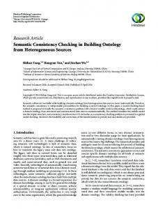
This constraint class defines the characteristics of correct functioning of Plain Old Telephone Services (POTS), which build the basis of any CTI application behaviour. This constraint class is still very general, and in practice relevant for each specific test scenario we consider. In the following, we consider some constraints explaining the end-user level behaviour of telephones: – ‘Digits test blocks are only allowed to appear after a corresponding offHook test block’, making sure that the phone is always properly initialized. ∀n. start ⇒ ( ¬digits(n) U offHook(n) ) – ‘Every offHook must be followed by an onHook for this device’. ∀n. offHook(n) ⇒ F ( onHook(n) ) – ‘An onHook can only be executed when an offHook was initiated for this device before’. ∀n. start ⇒ ( ¬onHook(n) U offHook(n) ) In fact Fig. 4 demonstrates a model checker-produced counterexample for the second property in terms of a violating path. Other constraints of this class concern the different signalling and communication channels of a modern phone with an end user: signalling via tones, 5
Our model checker actually also covers the full mu-calculus and could therefore address a direct formulation of this property.
Library-Based Design and Consistency Checking
245
messaging via display, optic signalling via LEDs, vibration alarm. They must all convey correct and consistent information, and possible degradation of service in exceptional cases must respect consistency and follow a set of well-defined precedence rules. For example, tones have highest priority, and in case of further urgent signalling a display message may be suppressed but not overtaken. Many other, somewhat more technical, constraints arise as soon as we consider also the switch side of the system. They concern, e.g.: – details of the communication protocols which regulates the communication between the switch and peripherals (here simple telephones), – the specific kind (analog, digital) of the protocol (e.g. ISDN, X25,...) – the layer in the protocol stack – variations of the protocol implementation specific to the vendor (here, Siemens), maybe even specific to single products or product lines. One sees immediately that manageable organization of the constraints is a key characteristic of a practicable solution. 5.3
Service Specific Test Cases
Modern midrange telephone systems for private use or in small businesses already include an amazing number of additional services in addition to POTS. For example: signalling of an additional incoming call (a feature known as Call Waiting), for ISDN systems the display of the caller’s number for incoming calls (Calling Number Delivery), conference calls (Three Way Calling), forwarding to other single or groups of numbers (Call Forwarding), embedded answering machine functionality (Voice Mail), and many more. Testing such a telephone system means evaluating the correct behaviour of a set of phones in the context of one or more of those activated features, which can be again described as a collection of sets of constraints [4,5]. 5.4
SUT Specific Test Cases
Considering concrete CTI settings like the one described in Fig. 2, we additionally need constraints about the correct initialization and functioning – of the single units of the SUT (e.g. single CTI applications, or the switch), – of the corresponding test tools, – and of their interplay. To give an idea of the complexity of the testing scenarios considered in practice, the concrete application already investigated in depth includes settings with a switch, up to eight phones of different nature, a complex CTI application with a server PC and a client PC serving several end-users, a running application suite, consisting of five programs, where the phones and the PC clients interact, and two test tools. The scenario is described in more detail in [9].
246
6
O. Niese et al.
Test Suite Development in the Integrated Testing Environment
The resulting overall lifecycle for test development using the ABC-based Test Coordinator is two-dimensional: both the application and the environment can grow and be enriched during the development process. 6.1
Test Case and Test Suite Development
Based on libraries of test blocks and constraints, an initial test graph is graphically constructed via drag-and-drop from the test block palette and subsequently validated either via graph tracing or under model checking control. In discussions with test engineers and test designers it turned out that only very few simple patterns of constraints are required in order to express most of the desired properties. Thus, end users of the testing environment should be able to input their own constraints on the basis of very few corresponding templates without requiting the help of experts in temporal logic. Test suites are then composed of suitable sets of test cases to cover a certain application. In the environment, distinct Constraint Libraries concern different aspects of the application: Figure 4, on the right, shows that the generic test library (ite) and the POTS libraries (phone) are currently loaded, and the specific constraints from those libraries have been selected for checking. Typically, a test graph is built and modified by test designers in an aspectdriven fashion: the testing expert chooses one or more constraints of interest, expressing single aspects of the test case under construction, checks online the correctness of the current test graph and modifies it in case of mistakes. This cycle is iterated until all relevant aspects have been treated. Due to the online verification with the model checker, constraint violations are immediately detected. 6.2
Strengthening the Testing Environment
The test graph and test suite development is superposed by an orthogonal process of incremental strengthening of the application-specific environment: this happens by successively adding further test blocks and consistency constraints. Both strengthenings proceed naturally, on demand, along the evolution of needs. Strengthening the Model. Entire new palettes of test blocks may turn out to become necessary when the environment or the application grow, e.g. to accommodate new test tools or new SUT’s (e.g., peripherals to the switch, mobile phones, applications, ...). Sometimes new single test blocks may also be needed e.g. when new releases of subsystems modify or extend their functionality. New test blocks are also defined for the purpose of better test organization (when it becomes clear that certain test graph fragments have a high potential for reuse). The latter situation is supported by ABC’s macro facility [19], which
Library-Based Design and Consistency Checking
247
essentially allows test designers to encapsulate (fragments of) test graphs as single, reusable test blocks. In the further development process, these blocks can be used just as ‘ordinary’ test blocks as shown in Fig. 3 (left): the test block marked with ‘M’ contains the full subgraph for Led and Display checks. Strengthening the Constraints. New constraints naturally arise when considering single new aspects of the current systems, and new Constraint Libraries when considering new applications or ways of interactions. Here we use SLTL constraints to describe in an abstract and loose way single aspects of the behaviour of a complex, distributed, heterogeneous system, which we can access only in a blackbox or at best graybox fashion. This looseness is essential as most of the hardware is sealed, and most of the software is third party.
7
Conclusions
We have presented a new coarse grain approach to automated integrated testing, which combines library-based test design, incremental formalization, and librarybased consistency checking via model checking. The impact of these features for the overall test process has been illustrated along an industrial application: an automated integrated testing environment for CTI-Systems. In fact, the gentle entry into practice due to incremental formalization was a ‘conditio sine qua non’ for the acceptance of the environment, because there has been some negative experience with formal methods in the past. The main reason for the failure of the prior approaches was their need of a full (formal) description of the SUT, which does not exists. Together with the early prototyping ability of the ABC, which allowed us to present a small running application within a couple of weeks, this won overall confidence for a long-term cooperation. Now, nine months after the first meeting, a prototype installation is already used by test engineers in Siemens’ test laboratories. We are convinced that our system will significantly reduce the testing effort, as already the untrained use of the only partially instantiated integrated test environment (ITE) led to noticeable reduction of the originally manual testing time. We are currently enforcing both training of the testers on the ITE, and refined instantiation with more test blocks, version information, and configuration constraints. This does not require any changes on the ITE itself, and we are optimistic that we will be able to give evidence in the very near future that these improvements indeed dramatically strengthen the impact of the ITE. Generalizations of the currently considered functional tests to other forms of testing like performance tests and stress tests are also possible, but require more effort and are planned for a successive project phase.
References 1. V. Braun, T. Margaria, B. Steffen, H. Yoo: Automatic Error Location for IN Service Definition, Proc. AIN’97, 2nd Int. Workshop on Advanced Intelligent Networks, Cesena, 1997.
248
O. Niese et al.
2. J.-C. Fernandez, C. Jard, T. J´eron and C. Viho: An Experiment in Automatic Generation of Test Suites for Protocols with Verification Technology, Science of Computer Programming, 29, 1997. 3. J. Hofmann: Program Dependent Abstract Interpretation, Diplomarbeit, Fakult¨ at f¨ ur Mathematik und Informatik, Universit¨ at Passau, August 1997. 4. B. Jonsson, T. Margaria, G. Naeser, J. Nystr¨ om, B. Steffen: On Modelling Feature Interactions in Telecommunications, Proc. of Nordic Workshop on Programming Theory, eds. B. Victor and W. Yi, 1999. 5. B. Jonsson, T. Margaria, G. Naeser, J. Nystr¨ om, B. Steffen: Incremental Requirements Specification of Evolving Systems, Feature Interactions in Telecommunications and Software Systems VI, eds. M. Calder and E. Magill, ISO Press, 2000. 6. T. Margaria, B. Steffen: Backtracking-free Design Planning by Automatic Synthesis in METAFrame Proc. FASE’98, Int. Conf. on Fundamental Aspects of Software Engineering, Lisbon, Apr. 1998, LNCS 1382, pp.188-204, Springer Verlag. 7. Mercury Interactive: Winrunner. http://www.winrunner.com 8. O. Niese, T. Margaria, M. Nagelmann, B. Steffen, G. Brune, H.-D. Ide: An open Environment for Automated Integrated Testing, 4th Int. Conf. on Software and Internet Quality Week Europe (QWE’00), Brussels (Belgium), November 2000, CD-ROM Proccedings, pp 584-593. 9. O. Niese, M. Nagelmann, A. Hagerer, K. Strunck, W. Goerigk, A. Erochok, B. Hammelmann: Demonstration of an Automated Integrated Testing Environment for CTI Systems, Proc. FASE 2001, this volume. Genova (I), 2001. 10. Object Management Group: The Common Object Request Broker: Architecture and Specification, Revision 2.3, Object Management Group, 1999. 11. The Raise Project homepage. http://dream.dai.ed.ac.uk/raise/ 12. Rational: The Rational Suite description. http://www.rational.com/products. 13. M. Schmitt, B. Koch, J. Grabowski, and D. Hogrefe, Autolink - A Tool for Automatic and Semi-automatic Test Generation from SDL-Specifications, Technical Report A-98-05, Medical Univ. of L¨ ubeck, Germany, 1998. 14. ITU-T Recommendation Z.100, CCITT specification and description language, ’93. 15. Sun: Java Remote Method Invocation. http://java.sun.com/products/jdk/rmi. 16. B. Steffen, T. Margaria, A. Claßen, V. Braun: Incremental Formalization: a Key to Industrial Success, in “Software: Concepts and Tools”, Vol.17(2), pp. 78-91, Springer Verlag, July 1996. 17. B. Steffen, T. Margaria, V. Braun: The Electronic Tool Integration Platform: Concepts and Design Int. Journ. on Software Tools for Technology Transfer (STTT), Vol. 1 N. 1+2, Springer Verlag, November 1997, pp. 9-30. 18. B. Steffen, T. Margaria: METAFrame in Practice: Intelligent Network Service Design, In Correct System Design – Issues, Methods and Perspectives, LNCS 1710, Springer Verlag, 1999, pp.390-415. 19. B. Steffen, T. Margaria, V. Braun, and N. Kalt: Hierarchical service definition, Annual Review of Communication, Int. Engineering Consortium (IEC), Chicago (USA), pages 847–856, 1997. 20. C. Stirling: Modal and Temporal Logics, In Handbook of Logics in Computer Science, Vol. 2, pp. 478 – 551, Oxford Univ. Press, 1995. 21. Telelogic: Telelogic Tau. http://www.telelogic.com. 22. J. Tretmans and A. Belinfante: Automatic testing with formal methods, In EuroSTAR’99: 7th European Int. Conference on Software Testing, Analysis & Review. EuroStar Conferences, Galway, Ireland, November 8–12, 1999.