Jan 20, 2009 - Jim Grundy. John O'Leary. Intel Strategic CAD Labs. {jim.d.grundy,john.w.oleary}@intel.com. Abstract. The Verilog ...... In William Pugh and.
Static Consistency Checking for Verilog Wire Interconnects ∗ Using Dependent Types to Check the Sanity of Verilog Descriptions Cherif Salama Gregory Malecha Walid Taha
Jim Grundy
Intel Strategic CAD Labs {jim.d.grundy,john.w.oleary}@intel.com
Rice University {cherif,gmalecha,taha}@rice.edu
Abstract The Verilog hardware description language has padding semantics that allow designers to write descriptions where wires of different bit widths can be interconnected. However, many of these connections are nothing more than bugs inadvertently introduced by the designer and often result in circuits that behave incorrectly or use more resources than required. A similar problem occurs when wires are incorrectly indexed by values (or ranges) that exceed their bounds. These two problems are exacerbated by generate blocks. While desirable for reusability and conciseness, the use of generate blocks to describe circuit families only makes the situation worse as it hides such inconsistencies making them harder to detect. Inconsistencies in the generated code are only exposed after elaboration when the code is fully-expanded. In this paper we show that these inconsistencies can be pinned down prior to elaboration using static analysis. We combine dependent types and constraint generation to reduce the problem of detecting the aforementioned inconsistencies to a satisfiability problem. Once reduced, the problem can easily be solved with a standard satisfiability modulo theories (SMT) solver. In addition, this technique allows us to detect unreachable code when it resides in a block guarded by an unsatisfiable set of constraints. To illustrate these ideas, we develop a type system for Featherweight Verilog (FV), a core calculus of structural Verilog with generative constructs and previously defined elaboration semantics. We prove that a well-typed FV description will always elaborate into an inconsistency-free description. We also provide a freely-available implementation demonstrating our approach. Categories and Subject Descriptors D.3.4 [Programming Languages]: Processors—Code generation; Preprocessors; F.3.3 [Logics and Meanings of Programs]: Studies of Program Constructs General Terms Languages, Standardization, Theory, Verification ∗ This
work was supported by the National Science Foundation (NSF) SoD award 0439017, and the Semiconductor Research Consortium (SRC) Task ID: 1403.001 (Intel custom project).
Permission to make digital or hard copies of all or part of this work for personal or classroom use is granted without fee provided that copies are not made or distributed for profit or commercial advantage and that copies bear this notice and the full citation on the first page. To copy otherwise, to republish, to post on servers or to redistribute to lists, requires prior specific permission and/or a fee. PEPM’09, January 19–20, 2009, Savannah, Georgia, USA. c 2009 ACM 978-1-60558-327-3/09/01. . . $5.00 Copyright
John O’Leary
Keywords Verilog Elaboration, Static Array Bounds Checking, Verilog Wire Width Consistency, Dead Code Elimination, Dependent Types
1.
Introduction
Digital circuit design is becoming increasingly complex. Processors nowadays have hundreds of millions of transistors. Hardware description languages (HDLs) like Verilog and VHDL would have been completely useless had they required the designers to describe the circuits they want to build at the transistor level. Thankfully, this is not the case. HDLs provide designers with various kinds of abstractions to be able to describe hardware at higher levels. For example, instead of using transistors, a designer can use gates, flipflops, latches, or complete hardware modules as circuit building blocks offering a hierarchal approach to hardware design. Productivity can be dramatically increased using higher levels of abstractions, which are therefore very desirable. Verilog (6) currently provides two types of constructs toward this end: • Behavioral Constructs: These constructs allow a designer to
describe a circuit functionality in a algorithmic way as one would do in C. The resultant description is suitable for simulation purposes but unless adhering to a rather ad hoc set of guidelines it cannot be synthesized into a hardware circuit. Even when synthesizable, the hardware designer has no control on the generated hardware. • Generative Constructs: These constructs allow a designer to
generically and structurally describe circuit families. These were introduced in the 2001 IEEE standard (5). They are particularly useful when describing frequently used modules that can be thought of as a library. When used correctly, generative constructs are fully synthesizable as they are replaced with purely structural code during a phase known as elaboration. In this work we are concerned only with generative constructs since we are interested about circuits whose structure can be reasoned about. We believe that generative constructs should be used more aggressively. Hardware designers are reluctant to adopt them because current tools do not provide enough support to make using them safe. Despite the fact that generative constructs only makes sense in the context of synthesizable circuits, current tools do not attempt to check for synthesizability statically (i.e. before elaboration), let alone statically checking for inconsistencies that Verilog tolerates due to its padding semantics. Most tools will accept a description, elaborate it, and then synthesize it into a graph of connected components known as a netlist. If anything goes wrong in the process, an elaboration or synthesis error is thrown depending on when the problem occurred. Even worse: due to Verilog’s padding semantics, some violations do not cause errors at all but
instead synthesize into a circuit that behaves incorrectly or uses more resources than required. To illustrate Verilog’s padding semantics and the kind of errors they can hide, let’s first consider a module that does not use any generative constructs at all:
A regularity can easily be detected either by looking at the code or at the schematic diagram. This regularity can be captured to generalize the definition to represent the whole family of N-bit synchronous counters instead of just the 4-bit synchronous counter in figure 1. The result is the following parameterized module using a generative loop:
module invert4(x, y); input [3 : 0] y; output [3 : 0] x; assign x = ~ y; endmodule
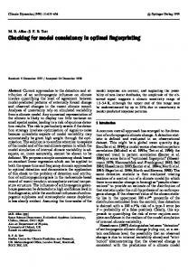
This module named invert4 is a 4-bit inverter. It has two 4-pin ports x and y where x is an output port and y is an input port. Pins of both ports are indexed from 0 to 3. The assignment statement uses a bitwise negation operator to invert all input bits and then connect each of them to the corresponding output pin. No padding semantics are used so far but what if the declaration of y was changed to input [4:0] y? What if instead the declaration of x was changed to output [4:0] x? In both cases, the assignment statement would be connecting two wires of incompatible widths. Surprisingly, this would still be considered to be a valid description due to Verilog’s padding (and trimming) semantics. In the first case the wider input signal will be trimmed discarding the most significant bit, while in the second case the slimmer input signal will be padded with an extra zero as its most significant bit. Note that in the first case, if the circuit is naively synthesized, an extra inverter will be used to invert the most significant input bit and then its output will be discarded. Let’s consider now a more interesting example: A 4-bit synchronous counter. The counter receives two inputs: a clock clk and an enable signal en. If en is high (equal to 1), then the 4-bit output count is incremented at each clock. The next output can be used to create a wider counter by connecting it to the en port of another counter thus cascading both. The schematic diagram in figure 1 shows how to construct such a counter out of T flip-flops and and gates.
Figure 1. A 4-bit synchronous counter using T flip-flops This module can be described using structural Verilog as follows: module counter4(count, next, en, clk); output [3 : 0] count; output next; input en; input clk; wire [4 : 0] t; assign t [0] = en; tflipflop tff_0 (count [0], assign t [1] = t [0] & count tflipflop tff_1 (count [1], assign t [2] = t [1] & count tflipflop tff_2 (count [2],
assign t [3] = t [2] & count [2]; tflipflop tff_3 (count [3], t [3], clk); assign t [4] = t [3] & count [3]; assign next = t[4]; endmodule
t [0], clk); [0]; t [1], clk); [1]; t [2], clk);
module counter_gen(count, next, en, clk); parameter N = 4; output [N - 1 : 0] count; output next; input en; input clk; wire [N : 0] t; genvar i; assign t [0] = en; generate for(i = 0;i < N;i = i + 1) begin tflipflop tff (count [i], t [i], clk); assign t [i + 1] = t [i] & count [i]; end endgenerate assign next = t [N]; endmodule
This module named counter_gen is parameterized by N whose default value can be anything (in this case we picked 4). This module now acts as a generator that can be run by instantiating the module with a particular parameter value. Each time this module is instantiated as part of a larger design, the width of the counter should be specified otherwise the default value is used. If this module is instantiated with N=4, the elaboration will create a specialized version of it which as expected will be identical to the first version we have written. In the generic version an off-by-one error causing array bounds violations can be easily introduced if the hardware designer inadvertently wrote the for-loop condition as i max(N, 0)). Otherwise stated we want to make sure that no integer value i can simultaneously satisfy the information we inferred from the loop invariant and be greater than the upper bound of count. If such a value is found then our program should be rejected. 2.5 Unreachable Code Detection The same satisfiability framework can be used to serve a slightly different purpose. It can be used to detect unreachable code. Consider the following example: module adder (sum, a, b); parameter N = 8; input [N-1 : 0] a; input [N-1 : 0] b; output [N : 0] sum; generate if(N