We also investigate the techniques to effi- ciently estimate and code the directional data, thus in- ... DPCM-based (Differential Pulse Code Modulation) [1] to.
Lifting-based Wavelet Transform with Directionally Spatial Prediction Wenpeng Ding1, Feng Wu2, Shipeng Li2 1) University of Science and Technology of China, HeFei 2) Microsoft Research China, Beijing ABSTRACT This paper incorporates the directionally spatial prediction (DSP) into the conventional lifting-based wavelet transforms and proposes a novel, efficient and flexible lifting structure (referred as DSP-lifting hereafter). Each lifting stage can be performed at the direction, where pixels have a strong correlation, rather than always at the horizontal or vertical direction. The proposed DSP enables the predicting and updating process at the fractional pixel without any constraint on the interpolation, which fully exploit the spatial correlation among pixels. Furthermore in the 2D transform, the direction of the first 1D transform is no longer requested to be vertical to that of the second so that the second 1D transform can utilize the spatial correlation better. The proposed DSP-lifting guarantees the perfect reconstruction. We also investigate the techniques to efficiently estimate and code the directional data, thus increasing the precision of spatial prediction and reducing the overhead bits. Experimental results have shown that the proposed DSP-lifting scheme can significantly outperform JPEG 2000 in terms of PSNR (up to 2dB) and visual quality.
1. INTRODUCTION Image compression is playing an important role in the modern life with the rapidly increasing in the amount of digital camera. Many compression schemes from early DPCM-based (Differential Pulse Code Modulation) [1] to DCT-based [2]~[4], again to wavelet-based [5]~[20], have been developed in past decades. The DCT-based schemes, like JPEG [2], usually offer a low computation solution, but they difficultly achieve the desired scalabilities. In comparison with the DCT-based schemes, the waveletbased schemes need more computational power. On the other hand, the wavelet transform [21] provides a multiscale representation of images in the space-frequency domain. Aside from the energy compaction and decorrelation properties that facilitate compression, a major advantage of the wavelet transform is its inherent scalabil-
ity. For example, the wavelet-based JPEG2000 standard [7] not only presents superior compression performance over the DCT-based JPEG standard, but also offers scalabilities in rate, quality and resolution that are very desirable for consumer and network applications. As a matter of fact, natural images often contain richly directional attributes, which can be commonly approximated as linear edges on a local level. These edges may be neither vertical nor horizontal. However, most mainstream image coding schemes do not take such a fact into account [2], [5]~[7], where 2D DCT or Wavelet transform is performed always at the horizontal and vertical directions. It would result in large magnitude in the high-frequency coefficients. In addition, at low bit-rates, the quantized effects can be observed clearly at image edges as the notorious Gibbs artifacts. This problem has been realized by many researchers [3], [4], [8]~[20]. Feig et al introduced spatial prediction into a JPEG-wise code in a manner similar to the fractal-based image compression [3]. It does not outperform the pure DCT-based one in terms of PSNR/ bit-rate trade-off. However, at very low bit-rates, it results in far fewer block artifacts and markedly better visual quality. Kondo et al performed the directional prediction on DCT block, which can be predicted from one of four coded neighboring DCT blocks [4]. The new video coding standard H.264 also successfully applied the block-based spatial prediction technique into the intra frame coding. It has shown significant gain on coding efficiency over that without spatial prediction [22]. There are many people who have investigated this problem in the wavelet/subband coding schemes. Ikonomopoulos et al proposed a fixed set of directional filters to adapt to texture correlation at different directions [8]. Li et al incorporated subband decomposition into the Ikonomopoulos’ scheme [9]. Bamberger et al used a filter bank based on a rectangular image sampling [10]~[12]. It can resolve images into many different directional components. Ridgelet and Curvelet recently developed by Candes et al are another kind of transforms with the polar sampling [13][14]. Mahesh et al decomposed hexagonally sampled
images into subbands that are selective in both frequency and orientation [15]. Taubman et al proposed a scheme, where the input image is first re-sampled before the wavelet transfrom [16]. The re-sampling process can rotate image edges to the horizontal or vertical direction. Wang et al used the similar idea from Taubman et al, but further proposed the overlapped extension to prevent coding artifacts around the boundaries of different direction regions [17]. Similar works on wavelet packet have been also reported in [18][19]. To our best knowledge, few authors propose to utilize the directional prediction into the lifting-based wavelet transform. The lifting structure developed by Daubechies et al is an efficient and popular implementation of wavelet transform, where every FIR (Finite Impulse Response) wavelet filter can be factored into several lifting stages [23]. The local spatial prediction can be readily incorporated into each lifting stage because it only involves a few local pixels in the calculation. In addition to the work presented in this paper, Boulgouris et al proposed an adaptive lifting to minimize the predicted error variance [20]. Similar to the idea from Ikonomopoulos, it derives several directional filters from the quincunx sampling and selects one of them with a median operation. But, it does not show the significant gain in lossless image coding. In this paper, we incorporate the directionally spatial prediction into the conventional lifting-based wavelet transforms and propose a novel, efficient and flexible DSPlifting. The proposed DSP-lifting still uses the popular Haar, 5/3 and 9/7 filters but owns the following features that never exist in the conventional lifting schemes. z
In each lifting stage, the predicting or updating signals do not always come from the horizontal or vertical samples. They can be selected along image linear edges so as to reduce the magnitude of high-pass coefficients.
z
For the purpose of the accurate spatial prediction, the predicting or updating signals may come from the fractional samples, which can be calculated with the existing interpolation. The DSP-lifting has no any constraint on the interpolation approach.
z
In order to guarantee the perfect reconstruction, the predicted and updated samples are always in integer positions.
z
When 2D transform is separated as two 1D transforms, the two 1D transforms are not necessary to be vertical in the DSP-lifting. But the split is performed at the horizontal and vertical directions so as to generate four rectangular subbands.
In addition, we also investigate the techniques to efficiently estimate and code the directional data, thus increasing the precision of spatial prediction and reducing the overhead bits. This is a key point to achieve the high performance in the DSP-lifting scheme. The proposed scheme is implemented in a JPEG2000-wise codec, where the DSP-lifting takes the place of the conventional lifting. The rest of this paper is arranged as follows. Section 2 describes the proposed DSP-lifting in details. The experimental results in Section 3 fully demonstrate the advantages of the proposed DSP-lifting. Section 4 further discusses the potential applications of the proposed DSPlifting. Finally, Section 5 concludes this paper. 2. THE PROPOSED DSP-LIFTING This section discusses the proposed DSP-Lifting from four aspects: lifting structure, interpolation, direction estimation and directional angle coding. 2.1 Lifting structure Let x ( m, n ) m , n∈Z be a 2D signal. Without loss of generality, we assume that this signal is first performed with 1D wavelet transform on the vertical direction and then on the horizontal direction. With the basic principle of lifting structure given in [23], each 1D wavelet transform can be factored into one or multiple lifting stages. A typical lifting stage consists of three steps: split, predict and update. Firstly, all samples are split into two parts: the even polyphase samples and the odd polyphase samples, ⎧ xe ( m, n ) = x (m,2n ) . (1) ⎨ x ( m , n ) = x ( m , 2 n + 1 ) ⎩ o In the predicting step, the odd polyphase samples are predicted from the neighboring even polyphase samples. The predicted residue is calculated with the following equation, (2) h ( m, n ) = xo ( m, n ) − Px ( m, n ) . e
In the conventional lifting, the predictions always come from the vertical neighboring even polyphase samples. However, the proposed DSP-lifting can select the best predictions from the surrounding even polyphase samples. As shown in Figure 1, assume that the pixels has a strong correlation at the angle θv , where the integer pixels are represented by the markers “ Ο ”, the half pixels by the markers “ × ” and the quarter pixels by the markers “ + ”. Therefore, the predictions of x ( m,2n + 1) come from the even polyphase samples pointed by the arrows in Figure 1. It is calculated as follows, (3) P ( m, n ) = p x ( m + sign(i − 1)tg (θ ), n + i ) . xe
∑ i
i
e
v
The conventional lifting can be viewed as the special case with θv = 0. The corresponding finite impulse response function is ie
P( z1 , z 2 ) = ∑ p i z1sign ( i −1) tg (θ v ) z 2i .
(4)
i = ib
In this paper, we consider the FIR wavelet filter in case only a finite number of coefficients pi are non-zero. Here let ib and ie be the smallest and largest integer number i , respectively, where pi is non-zero. After the calculation of Equation (2), we obtain a new representation of x(m, n) by replacing xo (m, n ) with the predicted residue h(m, n) . It is equivalent to x(m, n) . Since the prediction is always calculated from the even polyphase samples, given that the directional angle is known, the DSP-lifting can still perfectly reconstruct the odd polyphase samples with Equation (2).
− tg (θ ) Haar : ⎧⎪ P0 ( z1 , z 2 ) = −tgz1(θ ) , v
x ( m, n )
U 0 ( z1 , z 2 )
h ( m, n )
In the updating step, the even polyphase samples are replaced with (5) l ( m, n ) = xe ( m, n ) + U h (m, n ) . The DSP-lifting uses the same directional angle as that in the predicting step for saving the bits to code the angle data. Therefore, the updating signal of the even polyphase samples is given as (6) U ( m, n ) = u h ( m + sign ( j )tg (θ ), n + j ) . j
v
j
s0−1
x ( m, n )
U 0 ( z1 , z 2 )
P0 ( z1 , z2 )
z 2−1
s1−1
∑u z
z .
sign ( j ) tg (θv ) j j 1 2
For the purpose of the accurate spatial prediction, the proposed DSP-lifting allows the directional angle to point to the fractional pixels. In other word, tg (θ ) used in Equations (3) and (6) may be not an integer. Therefore, the interpolation technique is needed in this case. We will discuss the interpolation technique by using Equation (3) as an example. Firstly, for the perfect reconstruction, the integer pixels that are used to interpolate the fractional pixel should belong to xe ( m, n ) . It can not use any integer pixel from xo (m, n ) . The interpolation can be generally described as xe (m + sign(i − 1)tg (θ ), n + i ) = ∑ ak xe ( m + k , n + i ) . (11) k
The corresponding finite impulse response function is je
h ( m, n )
2.2 Interpolation
Figure 1: The angle of the vertical transform in the proposed DSP-lifting.
U ( z1 , z2 ) =
l ( m, n )
PK −1 ( z1 , z 2 ) U K −1 ( z1 , z2 )
Figure 2: The generic 1D DSP-lifting transform, (a) analysis side and (b) synthesis side.
θv
∑
(10)
s1
U K −1 ( z1 , z2 ) PK −1 ( z1 , z 2 )
h
(9)
s0
P0 ( z1 , z 2 )
z2
l ( m, n )
θv
(8)
v /2 ⎨U 0 ( z1 , z 2 ) = z1 ⎪ s s 1 = = 0 1 ⎩ ⎧ P0 ( z1 , z 2 ) = −( z1− tg (θ v ) + z1tg (θ v ) z 2 ) / 2 5/3 : ⎪ , tg (θ ) −tg (θ ) −1 ⎨U 0 ( z1 , z 2 ) = ( z1 v + z1 v z 2 ) / 4 ⎪ s0 = s1 = 1 ⎩ ⎧ P0 ( z1 , z 2 ) = −1.586134 × ( z1− tg (θ v ) + z1tg (θ v ) z 2 ) ⎪ tg (θ v ) − tg (θ v ) −1 z2 ) . 9/7 : ⎪U 0 ( z1 , z 2 ) = −0.05298 × ( z1 + z1 − tg (θ v ) + z1tg (θ v ) z 2 ) ⎪⎪ P1 ( z1 , z 2 ) = 0.882911 × ( z1 ⎨ tg (θ v ) + z1−tg (θv ) z 2−1 ) ⎪U 1 ( z1 , z 2 ) = 0.443506 × ( z1 ⎪ s0 = 1.230174 ⎪ ⎪⎩ s1 = 1 / s0
(7)
j = jb
jb and je be the smallest and largest integer number j , respectively, where u j is non-zero. Obviously, this step is
Here k is the integer around sign(i − 1)tg (θ ) and ak is the parameter of interpolation filter. After the z-transform of Equation (11), we can get z1sign( i −1) tg (θv ) =
ke
∑a z . k k 1
(12)
k = kb
trivially invertible with the known angle again. Given l ( m, n ) and h(m, n ) , we can perfectly reconstruct the even polyphase samples.
The parameter ak has a finite number of non-zero coefficients. In this paper, we adopt the popular Sinc interpolation, which decide the value ak . The interpolation of
The proposed DSP-lifting with different wavelet filters can be likewise described with a framework as shown in Figure 2. The proposed FIR functions of the Haar, 5/3 and 9/7 filters are given as follows,
Equation (6) uses the same way. 2.3 Direction estimation
The directional angles θ v and θ h of each sample are estimated locally at 16x16 block. As shown Figure 3, a 16x16 block can be partitioned into three modes: 16x16, 8x8 and 4x4. In the 16x16 mode, all pixels have the same directional angle. In the 4x4 mode, each block has 16 directional angles and all pixels in a 4x4 sub-block share the same angles. In addition, the finer of the predicted angle, the more accurate the spatial prediction is. From the knowledge of motion compensation in video coding, this paper prefers the predicted precision up to the quarter pixel.
2.4 Directional angle coding The directional angles are coded with a fixed VLC (variable length coding) table but with adaptively mapping. As shown in Figure 4, assume that the angle c of the current block is coded. The angles a, b and d of neighboring blocks are ready to predict the coded angle. We use the following criterion to select which angle is used as prediction, abs(b − d ) > abs(b − a ) . ⎧d (15) p=⎨ abs(b − d ) ≤ abs(b − a ) ⎩a In other words, if the angles b and d have a larger difference, the angle a is used as prediction; otherwise the angle d is used as prediction.
Figure 3: Three partition modes for estimating directional angles. The R-D algorithm is proposed to decide the predicted mode and directional angles of each 16x16 block. In the vertical lifting transform, the criterion to estimate the mode and directional angles is given as follows, E=
m0 +16 n0 +8
∑ ∑ h ( m, n ) + λ R . v
v
(13)
m = m0 n =n0
Here, h (m, n ) are the high-pass coefficients after the vertical transform, which can be calculated with Equation (2). Rv are the bits to code the mode and directional angles.
λv is the Lagrangian factor. ( m0 , n0 ) is the coordinates of the left-upper pixel of h (m, n ) . After the vertical lifting transform with the estimated directional data, we can get the low-pass signal l ( m, n ) and high-pass signal h ( m, n ) . They are continuously processed with the horizontal transform. In general, h ( m, n ) has less energy. It’s not worth to use another set of predicted modes and angles to horizontally transform the high-pass subband after the vertical decomposition. Therefore, h (m, n ) is decomposed at the horizontal direction. There is another set of predicted modes and angles to decompose l (m, n ) , where it may be different from that used in the vertical decomposition. The new criterion is given as follows, m1 +8 n1 +8
E = ∑ ∑ lh( m, n ) + λh Rh .
(14)
m = m1n =n1
Here, lh( m, n ) is the coefficient of the LH subband. Rh are the bits to code the mode and directional angles. λh is the Lagrangian factor. ( m1 , n1 ) is the coordinates of the leftupper pixel of lh( m, n ) .
Figure 4: The prediction of directional angle. The symbols of VLC table are assigned adaptively according to the predicted angle. The predicted angle is given as the shortest symbol, and other angles are assigned from short symbol to long one according the absolute difference between these angles and the predicted angle. After that, the current angle c is coded with the pre-determined table. 3. EXPERIMENTAL RESULTS The proposed DSP-lifting scheme has been implemented into JPEG 2000 reference software vm 9.0 and is compared with original JPEG 2000. The testing images, Barbara (512x512), Bike (2560x2048) and Cafe (2560x2048) from JPEG 2000 and the first frame of Foreman (352x288) from MPEG are used in this experiment. All experimental results are done with the 5/3 filter. The first experiment evaluates the ability of the proposed DSP-lifting on using the spatial correlation. We compared the results of the proposed DSP-lifting and the conventional lifting after a 2D decomposition. The prediction of the vertical lifting transform can be selected from [-45º,45º] with the quarter-pixel precision. In other words, the vertical lifting transform has 9 different angles. The prediction of the horizontal lifting transform can be selected as tg (θ h ) from [-2, 2] with the half-pixel precision. There are also 9 different angles. In this experiment, we do not consider the overhead bits for mode and directional angle coding. Each image is partitioned into 4x4 sub-blocks, and each sub-block can find the best direction. Table 1 shows the comparisons of the LH, HL, and HH subbands on the average absolute sum after the conventional lifting and DSP-lifting decomposition. The proposed DSP-Lifting technique shows excellent
performance on Barbara because it contains rich texture. The maximum reduction on the average absolute sum is 55.8% in the LH subband, 36% in the HL subband and 34.6% in the HH subband. It also shows significant reduction on other images. Table 1: The comparisons of the LH, HL and HH subbands on the average absolute sum. Average abs sum JPEG2000 L DSP H Reduce JPEG2000 H DSP L Reduce JPEG2000 H DSP H Reduce
Barbara 5.31 2.35 55.8% 2.26 1.44 36.0% 1.48 0.97 34.6%
Bike 3.01 2.25 27.3% 3.19 2.39 25.1% 1.05 0.88 15.5%
Cafe 5.01 4.04 19.2% 5.51 4.4 20.1% 1.56 1.5 4.5%
Foreman 1.3 0.92 24.3% 2.07 1.43 31.5% 0.6 0.51 16.0%
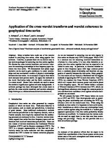
In the second experiment, we evaluate the coding efficiency and reconstructed visual quality. The mode and directional angles are selected with equations (13) and (14) and then are coded in the generated bitstream. All images are decomposed with three-layer wavelet transform. After the conventional lifting and DSP-lifting decomposition, the signals are coded with the same entropy coding. The PSRN versus bpp curves of four testing images are given in Figure 5. The DSP-lifting scheme outperforms JPEG2000 up to 2dB in Barbara, 1.5dB in Foreman, 0.7dB in Bike and 0.2dB in Cafe. Barbara
38
dB
36 34 32 30
JPEG2000 DSP-lifting
28 26 24
42 40 38 36 34 32 30 28 26
bpp 0
0.1 0.2 0.3 0.4 0.5 0.6 0.7 0.8 0.9
1
1.1
Foreman dB
JPEG2000 DSP-lifting bpp 0
0.1 0.2 0.3 0.4 0.5 0.6 0.7 0.8 0.9
1
1.1
40 38 36 34 32 30 28 26 24
Bike dB
JPEG2000 DSP-lifting bpp 0
1
1.1
Cafe
33 31 29 27 25 23 21 19
0.1 0.2 0.3 0.4 0.5 0.6 0.7 0.8 0.9
dB
JPEG2000 DSP-lifting bpp 0
0.1 0.2 0.3 0.4 0.5 0.6 0.7 0.8 0.9
1
1.1
Figure 5: The PSNR versus bpp curves. 4. OTHER APPLICATIONS Besides the image coding, the proposed DSP-lifting can also be applied into many other areas. Now, we mainly discuss two applications: spatial scalable video coding and low-delay wavelet video coding. (1) Spatial scalable video coding Spatial scalability is a much desired feature in the video coding especially with increasing wireless networks and portable devices. It is a hard nut to crack. Many researches have shown that the spatial scalability will considerably hurt the coding efficiency. One of solutions to achieve spatial scalability is to first decompose the video sequences into several four low-resolution sequences and then code them either jointly or separately. However, the high-pass sequences of them are difficultly compressed with the existing motion compensated schemes. With the help of the proposed DSP lifting, the high-pass sequences have much less energy because the correlation is removed with directionally spatial transform. Each high-pass sequences are compressed with the intra coding. (2) Low-delay 3D wavelet video coding MPEG is calling for proposals on scalable video coding. Most of the proposed schemes utilize the temporal wavelet decomposition. A big problem in these schemes is that the delay is quite large because of multiple-layer temporal decomposition. It can not satisfy the requirements from low-delay and real-time applications. With the proposed DSP-lifting, the 3D wavelet video coding schemes can reduce the number of temporal decompositions. The correlations among the low-band frames can be removed by the directional spatial prediction.
5. CONCLUSIONS This paper incorporates the directionally spatial prediction (DSP) into the conventional lifting-based wavelet transforms and proposes the DSP-lifting technique. The proposed DSP-lifting still utilizes the existing wavelet filters, such as Haar, 5/3 or 9/7. But each lifting stage can be performed along the direction, where image pixels have a strong correlation, rather than always at the horizontal or vertical direction. Even though the predicting and updating signals comes from fractional pixels, the proposed DSPlifting can guarantee the perfect reconstruction without any constraint on interpolation. After one layer 2D decomposition, the DSP-lifting has much less the absolute sum on the LH, HL and HH subbands than the conventional lifting. Furthermore, the reconstructed PSNR and visual quality of the DSP-lifting after multiple layer decomposition are much better than that of JPEG2000. Besides the image coding, the proposed technique can be also applied to the in-band wavelet video coding and the low-band frame coding of 3D video coding. References: [1] A. Habibi, R. S. Hershel, “A unified representation of differential pulse-code modulation (DPCM) and transform coding systems,” IEEE trans. on communications, vol. 22, no 5, 692-696, 1974. [2] W. B. Pennebaker and J. L. Mitchell, “JPEG still image data compression standard,” New York: Van Nostrand, 1993. [3] E. Feig, H. Peterson, V. Ratnakar, Image compression using spatial prediction, ICASSP, vol. 4, 2339-2342, 1995. [4] H. Kondo, Y. Oishi, Digital image compression using directional sub-block DCT, International Conference on Comm. Technology, vol. 1, 21-25, 2000. [5] J. M. Shapiro, “Embedded image coding using zerotree of wavelet coefficients,” IEEE trans. Signal Processing, vol. 41, no 12, 3445-3462, 1993 [6] A. Said and W. A. Pearlman, “A new fast and efficient image codec based on set partitioning in hierarchical trees,” IEEE trans. on CSVT, vol. 6, no 3, 243-250, 1996. [7] D. Taubman and M. Marcellin, “JPEG2000: Image Compression Fundamentals, Standards, and Practice,” Kluwer Academic Publishers, 2001. [8] A. Ikonomopoulos and M. Kunt, “High compression image coding via directional filtering,” Signal Processing, vol. 8, no 2, 179-203, 1985. [9] H. Li and Z. He, “Directional subband coding of images,” ICASSP, vol. 3, 1823-1826, 1989. [10] R. H. Bamberger, M. Smith, “A filter bank for the directional decomposition of images: theory and design,” IEEE trans. on Signal Processing, vol. 40, no 4, 882-893, 1992.
[11] R. H. Bamberger, M. Smith, “Narrow band analysis of a filter bank for the directional decomposition of images,” ICASSP, vol. 3, 1739-1742, 1990. [12] R. H. Bamberger, M. Smith, “A comparison of directionally-based and nondirectionally-based subband image coders,” in Proc. SPIE, VCIP, 1605, vol.2, 757-768, 1991. [13] E. J. Candes, “Monoscale ridgelets for the representation of images with edges,” Dept. Statistic, Stanford Univ., Tech. Reporter, 1999. [14] E. J. Candes and D. L. Donoho, “Curvelets,” Available: http://wwwstat.stanford.edu/~donoho/reports/1999/curvelets.pdf. [15] B. Mahesh and W. A. Pearlman, “Hexagonal sub-band coding for inages,” ICASSP, vol. 3, 1953-1956, 1989. [16] D. Taubman and A. Zakhor, “Orientation adaptive subband coding of images,” IEEE trans. on Image Processing, vol. 3, no 4, 421-437, 1994. [17] D. Wang, L. Zhang and A. Vincent, “Curved wavelet transform for scalable video coding,” ISO/IEC JTC1/SC29/WG11, MPEG doc M10535, Munich, 2004. [18] C. N. Zhang and X. Wu, “A hybrid approach of wavelet packet and directional decomposition for image compression,” IEEE Canadian Conf. on Electrical and Computer Engineering, vol. 2, 755-760, 1999. [19] P. Carre, E. Andres, C. F. Maloigne, “Discrete rotation for directional orthogonal wavelet packets,” ICIP, vol. 2, 257260, 2001. [20] N. V. Boulgouris, D. Tzovaras, M. G. Strintzis, Lossless image compression based on optimal prediction, adaptive lifting, and conditional arithmetic coding, IEEE trans. on Image Processing, vol. 10, no. 1, 1-14, 2001. [21] M. Vetterli and J. Kovacevic, “Wavelets and subband coding,” Prentice Hall Englewood Cliffs, NJ 1995. [22] T. Wiegand, G. J. Sullivan, G. Bjntegaard, A. Luthra, Overview of the H.264/AVC video coding standard, IEEE trans. CSVT, vol. 13, no. 7, 2003. [23] I. Daubechies and W. Sweldens, “Factoring wavelet transforms into lifting steps,” Journal of Fourier Anal. Appl., vol. 4, no 3, 247-269, 1998.