ing image guided filtering to remove ringing artifacts. Results show that significant improvement can be achieved compared to state-of-the-art methods, for both ...
LIGHT FIELD SUPER-RESOLUTION VIA LFBM5D SPARSE CODING Martin Alain, Aljosa Smolic V-SENSE Project, School of Computer Science and Statistics, Trinity College, Dublin 𝑠
ABSTRACT
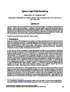
Light fields emerged as a new imaging modality, enabling to capture all light rays passing through a given amount of the 3D space [1]. Compared to traditional 2D imaging systems which only capture the spatial intensity of light rays, a 4D light field also contains the angular direction of the rays. We adopt in this paper the common two-plane parametrization, and a light field can be formally represented as a 4D function Ω × Π → R, (x, y, s, t) → L(x, y, s, t) in which the plane Ω represents the spatial distribution of light rays, indexed by (x, y), while Π corresponds to their angular distribution, indexed by (s, t). Perhaps the easiest way to visualize a light field is to consider it as a matrix of views (see Fig. 1), also called sub-aperture images (SAI). Each SAI represents a 2D slice of the light field over the spatial dimensions (x, y ). Another common representation of light fields are Epipolar Plane Images (EPI), which are 2D slices of the 4D light field obtained by fixing one spatial and one angular dimension (sx- or yt-planes, see Fig. 1). Applications of light field include post-capture refocusing [2], free viewpoint rendering [1, 3], or depth estimation [4]. This publication has emanated from research conducted with the financial support of Science Foundation Ireland (SFI) under the Grant Number 15/RP/2776. This work was supported by TCHPC (Research IT, Trinity College Dublin). All calculations were performed on the Lonsdale cluster maintained by the Trinity Centre for High Performance Computing. This cluster was funded through grants from SFI.
𝑡
… 𝑡
𝑦
𝑦
…
1. INTRODUCTION
𝑥
…
Index Terms— Light Fields, Super-Resolution, Sparse Coding, Back-Projection, Guided Image Filtering
…
…
In this paper, we propose a spatial super-resolution method for light fields, which combines the SR-BM3D single image superresolution filter and the recently introduced LFBM5D light field denoising filter. The proposed algorithm iteratively alternates between an LFBM5D filtering step and a back-projection step. The LFBM5D filter creates disparity compensated 4D patches which are then stacked together with similar 4D patches along a 5th dimension. The 5D patches are then filtered in the 5D transform domain to enforce a sparse coding of the high-resolution light field, which is a powerful prior to solve the ill-posed superresolution problem. The back-projection step then impose the consistency between the known low-resolution light field and the-high resolution estimate. We further improve this step by using image guided filtering to remove ringing artifacts. Results show that significant improvement can be achieved compared to state-of-the-art methods, for both light fields captured with a lenslet camera or a gantry.
𝑥
𝑦
… 𝑥 𝑠
Fig. 1. Examples of light field representations: matrix of subaperture images (SAI) (left); and Epipolar Plane Images (EPI) (right) shown below and on the right of the center SAI.
Single image super-resolution (SISR) is a major research topic in image processing which has lead to very advanced methods [5–15]. Light field super-resolution (LFSR) has thus also become a very active research area in the more recent years. In the case of light fields, super-resolution can be applied on the spatial dimensions, i.e. to increase the SAIs resolution, or on the angular dimension, i.e. to synthesize new views, or both. We focus in this paper on spatial LFSR only. Formally, we model the link between low- and high-resolution light fields as follows: LL = Dα LH
(1)
where LH is the high-resolution light field (HRLF) that we want to reconstruct, LL is the known low-resolution light field (LRLF), and Dα encodes blurring and downsampling of each SAI by a factor α. The LFSR problem described by Eq. 1 is ill-posed with many possible HRLF LH which can produce the known LRLF LL . Research from SISR showed that introducing an image prior is a powerful way to solve this problem, e.g. the popular sparse representations [9]. Learning based methods modeling the relation between known pairs of low- and high-resolution images have also been successfully applied to SISR [11–13]. A naive approach to LFSR thus consists in applying existing SISR methods to each SAI independently. However, such approaches do not take into account the specific 4D light field structure described above. To address this limitation, Mitra and Veeraraghavan [16] proposed to model 4D light field patches with Gaussian Mixture Models (GMMs), assuming the disparity is constant within each 4D patch. GMMs are learned on a known set of 4D high-resolution patches with different disparity values. Low-resolution 4D patches are then super-resolved using a linear
minimum mean square error estimator. Yoon et al. [17] extended the work of [11] and used a deep-learning based approach to address both spatial and angular super-resolution of light fields. In [18], Farrugia et al. recently proposed to learn a linear subspace mapping between known low- and high-resolution volumetric light field patches. The volumetric patches are obtained by stacking together the 2D patches constituting a 4D patch along a 3rd dimension. The high dimensonality of these volumetric patches is reduced using PCA, and a mapping is learned between the lowand high-resolution subspace using ridge regression. The learned PCA and mapping can then be applied on LRLFs to perform either spatial or angular super-resolution. Non-learning based approaches have also been proposed such as in [19], where Wanner and Goldluecke introduced a variational framework in which new high-resolution SAIs are synthesized from known low-resolution ones using depth information estimated from the EPIs. Recenlty, Rossi and Frossard [20] proposed an approach inspired by multiframe super-resolution [5] coupled with a graph prior to capture the light field structure, which avoids an explicit disparity computation. In this paper, we propose to combine the iterative SR-BM3D SISR method [10], derived from the BM3D single image denoising filter [21], and the LFBM5D light field denoising filter [22], which extends the concepts of BM3D to light fields. First, the LFBM5D filter is applied on the current estimate of the HRLF. During this step, 5D patches are first transformed in a 5D transform domain. Due to the highly redundant nature of light field patches, the 5D spectrum obtained is very sparse, and hard-thresholding is further applied on the coefficients. This step can be interpreted as enforcing a sparse prior on the light field. Second, back-projection is applied for each SAI of the light field. Back-projection consists in upsampling the residual error between the known LF image and the downsampled current HR estimate. The upsampled residual error is then added back to the current HR estimate to create a new one. The process iterates until convergence. Back-projection suffers from known ringing artifacts, especially for high magnification factors. We propose in this paper to use image guided filtering to improve this step. This paper is organized as follows. Section 2 describes in detail the proposed SR-LFBM5D approach. We evaluate in section 3 the performances of our approach against state-of-the-art methods, followed by conclusion in section 4. 2. SR-LFBM5D In this section, we describe our method called SR-LFBM5D. We first recall the main principle of the LFBM5D denoising filter and how it can be interpreted as a light field sparse coding operator. We then cast the LFSR problem of Eq. 1 into an optimization problem based on a sparse prior, and detail the algorithm used to solve it. 2.1. Light field sparse coding with LFBM5D The core idea of the LFBM5D filter is to exploit redundancies over the light field angular and spatial dimensions, as well as self-similarities occurring in natural images. For that purpose, 5D patches are built from similar 2D patches, and filtered in the 5D transform domain. As the 5D transform is applied on a very
5D patch
𝐼𝑟𝑒𝑓 𝑃
4D patch 2D spatial patch 2D angular patch
Fig. 2. 4D patches are obtained by taking disparity compensated 2D patches in the neighboring SAIs with respect to the current reference 2D patch. 5D patches are finally built by stacking similar 4D patches along a 5th dimension. redundant signal, the spectrum obtained is very sparse. Sparsity is further enforced by applying hard-thresholding on the 5D transform coefficients. The LFBM5D ouput is then obtained by applying the inverse 5D transform on the filtered 5D spectrum. 5D patches are obtained using the following procedure, illustrated in 2. Considering a 2D patch P in a so-called reference SAI, a 4D patch is first created by finding in each neighboring SAI the 2D patch closest to P , which can be assimilated to a disparity compensation step using a block matching algorithm. Patches whose Euclidean distance is superior to a given threshold τdisp are discarded in order to be robust to occlusions. This ensures the smoothness and homogeneity of 2D patches taken along the angular dimensions (also called 2D angular patches, see Fig. 2), and guarantees to obtain a sparse representation in the transform domain. We then search for a set of patches similar to P in the reference SAI such that their Euclidean distance is inferior to a threshold τsim . Finally, the 5D patch is built by stacking along a 5th dimension the 4D patches built from all patches similar to the reference patch. The 5D transform consists in practice of three cascaded transforms: a normalized 2D DCT is applied on the spatial dimensions of the 5D patch, followed by a 2D shape-adaptive DCT (SADCT) [23] applied on the angular dimensions. Finally, a 1D Haar wavelet is applied on the 5th dimension of the 5D patch. We illustrate the interest of cascading 2D angular and spatial transforms in Fig. 3, where the 4D transform spectrum obtained from the combination of the 2D transforms is clearly sparser than the 2D transform spectra. The spectum of a 5D patch would be further compacted when the 1D transform is applied over the 5th dimension. This succession of localized patch-based operations can be interpreted as a more global process, as shown in [24] for the BM3D filter. The authors of [24] formally demonstrate that the BM3D filtering of a whole image can be understood as a the projection of this image over a BM3D frame. We extend here this concept to LFBM5D frames. More precisely, the forward transform step, also called analysis, is formulated as ω = Φl , where l is the vector notation of a light field L, the matrix Φ is the analysis frame of LFBM5D, and ω is the resulting spectrum. The inverse transform, or synthesis, is formulated as l = Ψω , where the matrix Ψ is the synthesis frame of LFBM5D.
𝑠
𝑓𝑠
𝑡
𝑓𝑡 2D angular transform
𝑥 𝑦
Fig. 4. Back-projection without (left) and with (right) guided image filtering, α = 4.
𝑓𝑠
2D spatial transform
𝑓𝑡 𝑓𝑥
𝑓𝑥 𝑓𝑦
𝑓𝑦
Fig. 3. Example of a 4D transform spectrum (bottom right) obtained for a 4D patch (top left) taken from the Lego Knights light field. The 4D transform is obtained by cascading a 2D spatial transform (bottom left) and a 2D angular transform (top right). In this example the 2D DCT was used for both transforms. Notice that the 4D transform spectrum is sparser than the individual 2D transform spectra.
2.2. Application to LFSR The formal frame interpretation of the LFBM5D filter described above can be used to introduce a sparse prior in the superresolution problem defined in Eq. 1. Using vector notations, the sparse reconstruction of a HRLF l H is formulated as the following minimization problem: 1 ω k0 , min kll L − D αl H k22 + λω kω ω 2
l H = Ψω
(2)
where l L is the known LRLF, the matrix D α corresponds to the blurring and downsampling opetator of Eq. 1, ω is the LFBM5D spectrum, and Ψ is the LFBM5D synthesis frame. The first summand in Eq. 2 represents the data term enforcing the coherence between the HRLF and the LRLF according to the LFSR model of Eq. 1, while the second summand is a regularization term imposing the sparsity of the HRLF. By applying a multiple-criteria Nash equilibrium technique, the authors of [10] derive the following two-step iterative solution: Φl iH , τHT ) Step 1: ω i = γ(Φ
(3)
where γ√represents a hard-thresholding operator with threshold τHT = 2λω , and i is the iteration index. This step corresponds to the forward transform and hard-thresholding of the LFBM5D filter. i U α (ll L − D αl iH ) Step 2: l i+1 H = l H + βU
(4)
where l iH = Ψω i is the estimated HRLF obtained after applying the inverse transform on the hard-thresholded spectrum obtained at step 1, and U α is an upsampling matrix nearly compensating D α . This step corresponds to back-projection, which enforces the minimization of the data term in Eq. 2. It can be compared to the well known iterative back-projection algorithm (IBP) [5],
with the notable difference that we perform filtering in the loop. Traditional IBP suffers from known ringing artifacts [6], which are partially reduced by the filtering step, especially when increasing the number of iterations. However, ringing artifacts can still be observed for high magnification factors (α = 4) as shown in Fig. 4. In this paper we propose to use guided image filtering [25] to prevent such artifacts from appearing. In fact, we observe that the ringing artifacts appear around strong edges (see Fig. 4) due to the upsampling of the low-resolution residual error, and are propagated through the iterative loop. We choose the guided image filter as it is able to preserve in the filtered output the edges of a given guidance image. Therefore for each SAI of the light field we apply the image guided filter to the upsampled low-resolution residual error, using the initial high-resolution estimate of the SAI as a guide. We denote this operation light field guided filtering. The image guided filter ensures that the high frequency added by the back-projection correspond to existing edges in the original SAI, as shown in Fig. 4, while using the original HRLF estimate as a guide avoids propagating artifacts over the iterations. The overall algorithm is summarized in Alg. 1, using light field variables instead of the vector notations used above. LF BM 5D(L, τHT ) denotes the LFBM5D hard-threshlding of the light field L using threshold τHT . The light field guided filter is noted GF (L, G), where L is the light field to filter and G is the guidance light field.
Algorithm 1 SR-LFBM5D Input: LL , L0H , M , Dα , Uα Output: LM H for i = 0 . . . M do LiH = LF BM 5D(LiH , τHT ) Lerr = Uα (LL − Dα LiH ) if α == 4 then Lerr = GF (Lerr , L0H ) end if Li+1 = LiH + βLerr H end for
3. RESULTS We discuss in this section the performance of the proposed approach against relevant state-of-the-art methods. LRLFs are obtained using a Gaussian blurring kernel applied on each SAI, followed by down-scaling by a factor α = 2, 3, 4. We use Gaussian filters with standard deviation 1.6 and sizes 7 × 7, 9 × 9 and 11 × 11 for α = 2, 3, 4 respectively. The first HRLF estimate L0H is obtained by applying the bicubic filter to every
Table 1. Average performances in PSNR. Best and second best values highlighted in red and blue respectively. Lytro Illum Bicubic SR-BM3D [10] BM+PCA+RR [18] GB [20] Proposed 1st step Proposed 2nd step
α=2 27.78 / 0.01 30.21 / 0.01 29.95 / 0.01 29.80 / 0.01 30.17 / 0.01 30.25 / 0.01
α=3 26.08 / 0.01 28.45 / 0.01 28.55 / 0.01 28.65 / 0.01 28.62 / 0.01 28.60 / 0.01
α=4 24.62 / 0.00 26.58 / 0.01 27.08 / 0.01 27.45 / 0.01 26.87 / 0.01 26.82 / 0.01
Stanford Bicubic SR-BM3D [10] BM+PCA+RR [18] GB [20] Proposed 1st step Proposed 2nd step
α=2 29.00 / 0.01 34.10 / 0.01 32.81 / 0.04 33.01 / 0.02 34.15 / 0.01 34.27 / 0.01
α=3 26.81 / 0.01 30.90 / 0.01 30.85 / 0.03 31.42 / 0.01 31.81 / 0.01 31.77 / 0.01
α=4 25.06 / 0.01 28.00 / 0.02 28.73 / 0.02 29.44 / 0.04 29.10 / 0.02 29.02 / 0.02
SAI of LL . We also use the bicubic filter for the upsampling operator Uα . The experiments are conducted on a first dataset of twelve light fields captured with a Lytro Illum camera taken from the EPFL [26] and INRIA datasets [27], and a second dataset of twelve light fields from Stanford captured with a gantry [28]. Following [20], and as we focus on spatial SR, we only used the 5 × 5 center SAIs of the light fields to reduce the computation time. For the Lytro Illum dataset, the SAIs of resolution 434 × 625 were extracted using a modified version of the method proposed in [29] (see detailed explanations online1 ). Note that for the Stanford dataset, the spatial resolution of the SAIs was cropped to 512 × 512 pixels to speed up the experiments. For the LFBM5D step, we use patches of size 8 × 8 and 3 × 3 over the spatial and angular dimensions respectively. A maximum of 32 patches is retained along the 5th dimension. We set τ disp = τsim = 3000. Following [10], the threshold τHT varies with the iterations as a quadratic function from 12α to α. The filter is applied in the YCbCr color space. For the back-projection step, we set β = 1.75 as in [10], and we use the bicubic filter to upsample the residual error. We set the number of iterations to M = 10, 30, 50 for α = 2, 3, 4 respectively. We compare our method to the work of [18, 20], denoted BM+PCA+RR and GB respectively, as these two recent methods were shown to outperform previous techniques presented in Sec. 1. We also apply the SR-BM3D method to each SAI independently. We evaluate the LFSR performances using the PSNR. For each light field, the mean PSNR and variance are computed over all SAIs. As shown in Fig. 5, the method in [20] suffers from border effects, thus a border of 16 pixels was removed from each SAI before the PSNR computation. We give in Table 1 the results for both the Lytro Illum and the Stanford datasets. Note that we report averaged values over each dataset. Detailed results are available online1 . Results show that the proposed method clearly outperforms existing LFSR methods for both datasets for α = 2. For α = 3, our method still performs best on the Stanford dataset, but only second best on the Lytro Illum dataset. For α = 4, our method performs second best on the Stanford dataset, but is out1 https://v-sense.scss.tcd.ie/?p=1551
Original
Bicubic PSNR = 28.57 dB
BM+PCA+RR PSNR = 32.47 dB
GB PSNR = 32.65 dB
SR-BM3D PSNR = 34.34 dB
SR-LFBM5D PSNR = 34.74 dB
Fig. 5. Visual results of LFSR with α = 2 on the center SAI of the Lego Knights light field from the Stanford dataset. (Best viewed in color and zoomed)
performed on the Lytro Illum dataset. This suggests that our method is better suited than state-of-the-art techniques for light fields with a wide baseline. We observe that SR-BM3D performs surprisingly well for α = 2 and even outperforms existing LFSR methods. Note however that this result does not hold for higher magnification factors α = 3, 4, which demonstrates the need for LF dedicated methods. We show visual comparisons on the center SAIs of the light field in Fig. 5. We observed that the use of the guided light field filtering in the back-projection step for α = 4 gives an average increase in PSNR of about 1dB for both datasets. 4. CONCLUSION We introduced in this paper a novel light field super-resolution method, combining the state-of-the-art SR-BM3D single image super-resolution filter and the LFBM5D light field denoising filter. By interpreting the LFBM5D filtering as a sparse coding operation, we can cast the ill-posed super-resolution problem into an optimisation problem based on a sparsity prior. The algorithm alternates between the LFBM5D hard-thresholding step and a back-projection step. In addition, we propose to use light field guided filtering to reduce the ringing artifacts generated by the back-projection. Results show that the proposed approach performs especially well for light fields captured with a wide baseline (such as the Stanford dataset) or low magnification factors. In order to further improve the performances of our approach for dense light fields (e.g. captured with a Lytro Illum) and for high magnification factors, we plan to modify our optimisation problem to include insights from multi-frame super-resolution, such as in [20]. An additional hypothesis can in fact be made, which postulates that a high-resolution SAI can not only generate a low-resolution SAI at the same angular position, but also of the neighboring SAIs. This would essentially impact the backprojection step of our algorithm, where the low-resolution residual error upsampling would not only come from the corresponding SAI, but also the surrounding ones.
5. REFERENCES [1] M. Levoy and P. Hanrahan, “Light field rendering”, in Proc. SIGGRAPH, 1996, pp. 31–42. [2] R. Ng, M. Levoy, M. Br´edif, G. Duval, M. Horowitz, and P. Hanrahan, “Light Field Photography with a Hand-Held Plenoptic Camera”, Tech. Rep., CSTR 2005-02, Apr. 2005. [3] A. Isaksen, L. McMillan, and S. J. Gortler, “Dynamically reparameterized light fields”, in Proc. SIGGRAPH, 2000, pp. 297–306. [4] B. Goldluecke, “Globally consistent depth labeling of 4d light fields”, in Proc. CVPR, 2012, pp. 41–48. [5] M. Irani and S. Peleg, “Motion analysis for image enhancement: Resolution, occlusion, and transparency”, Journal of Visual Communication and Image Representation, vol. 4, no. 4, pp. 324 – 335, 1993. [6] Y.-W. Tai, W.-S. Tong, and C.-K. Tang, “Perceptuallyinspired and edge-directed color image super-resolution”, in Proc. CVPR, 2006, vol. 2, pp. 1948–1955. [7] H. Chang, D.-Y. Yeung, and Y. Xiong, “Super-resolution through neighbor embedding”, in Proc. CVPR, June 2004, vol. 1, pp. 1275–1282. [8] D. Glasner, S. Bagon, and M. Irani, “Super-resolution from a single image”, in Proc. ICCV, Sept 2009, pp. 349–356. [9] J. Yang, J. Wright, T. S. Huang, and Y. Ma, “Image superresolution via sparse representation”, IEEE Trans. on Image Process., vol. 19, no. 11, pp. 2861–2873, Nov 2010. [10] K. Egiazarian and V. Katkovnik, “Single image superresolution via BM3D sparse coding”, in Proc. EUSIPCO, Aug 2015, pp. 2849–2853. [11] C. Dong, C. C. Loy, K. He, and X. Tang, “Learning a deep convolutional network for image super-resolution”, in Proc. ECCV, 2014, pp. 184–199. [12] K. Zhang, B. Wang, W. Zuo, H. Zhang, and L. Zhang, “Joint learning of multiple regressors for single image super-resolution”, IEEE Signal Processing Letters, vol. 23, no. 1, pp. 102–106, Jan 2016. [13] J. S. Choi and M. Kim, “Single image super-resolution using global regression based on multiple local linear mappings”, IEEE Trans. on Image Process., vol. 26, no. 3, pp. 1300–1314, March 2017. [14] R. Timofte, V. DeSmet, and L. VanGool, “A+: Adjusted anchored neighborhood regression for fast super-resolution”, in Proc. ACCV, 2015, pp. 111–126. [15] C. Ledig, L. Theis, F. Huszar, J. Caballero, A. Cunningham, A. Acosta, A. P. Aitken, A. Tejani, J. Totz, Z. Wang, and W. Shi, “Photo-realistic single image super-resolution using a generative adversarial network”, in Proc. CVPR, 2017, pp. 105–114.
[16] K. Mitra and A. Veeraraghavan, “Light field denoising, light field superresolution and stereo camera based refocussing using a GMM light field patch prior”, in Proc. CVPR Workshops, jun 2012, pp. 22–28. [17] Y. Yoon, H. G. Jeon, D. Yoo, J. Y. Lee, and I. S. Kweon, “Learning a deep convolutional network for light-field image super-resolution”, in Proc. ICCVW, Dec 2015, pp. 57– 65. [18] R. A. Farrugia, C. Galea, and C. Guillemot, “Super resolution of light field images using linear subspace projection of patch-volumes”, IEEE Journal of Selected Topics in Signal Processing, vol. 11, no. 7, pp. 1058–1071, Oct 2017. [19] S. Wanner and B. Goldluecke, “Variational light field analysis for disparity estimation and super-resolution”, IEEE Trans. on Pattern Analysis and Machine Intelligence, vol. 36, no. 3, pp. 606–619, March 2014. [20] M. Rossi and P. Frossard, “Graph-based light field superresolution”, in Proc. MMSP, Oct 2017, pp. 1–6. [21] K. Dabov, A. Foi, V. Katkovnik, and K. Egiazarian, “Image Denoising by Sparse 3-D Transform-Domain Collaborative Filtering”, IEEE Trans. on Image Process., vol. 16, no. 8, pp. 2080–2095, 2007. [22] M. Alain and A. Smolic, “Light field denoising by sparse 5D transform domain collaborative filtering”, in Proc. MMSP, Oct 2017, pp. 1–6. [23] A. Foi, V. Katkovnik, and K. Egiazarian, “Pointwise shapeadaptive DCT for high-quality denoising and deblocking of grayscale and color images”, IEEE Trans. on Image Process., vol. 16, no. 5, pp. 1395–1411, May 2007. [24] A. Danielyan, V. Katkovnik, and K. Egiazarian, “BM3D frames and variational image deblurring”, IEEE Transactions on Image Process., vol. 21, no. 4, pp. 1715–1728, April 2012. [25] K. He, J. Sun, and X. Tang, “Guided image filtering”, IEEE Trans. on Pattern Analysis and Machine Intelligence, vol. 35, no. 6, pp. 1397–1409, June 2013. [26] M. Rerabek and T. Ebrahimi, “New Light Field Image Dataset”, in Proc. QoMEX, 2016. [27] “INRIA Lytro Illum dataset”, http://www. irisa.fr/temics/demos/lightField/CLIM/ DataSoftware.html, accessed: 28-01-2018. [28] “The Stanford light field archive”, http: //lightfield.stanford.edu/lfs.html, accessed: 28-01-2018. [29] P. David, M. L. Pendu, and C. Guillemot, “White lenslet image guided demosaicing for plenoptic cameras”, in Proc. MMSP, Oct 2017, pp. 1–6.