Department of Automatic Control, Lund Institute of Technology, Box 118, S-221 00 Lund, Sweden ... limits the achievable performance of a control system.
European Journal of Control (2000)6:2-20
European Journal of Control
© 2000 EUCA
Limitations on Control System Performance K.J. Astrom Department of Automatic Control, Lund Institute of Technology, Box 118, S-221 00 Lund, Sweden
Many different factors such as process dynamics, disturbances, process uncertainties and actuator saturation have to be considered when designing a control system. It is important to be aware offactors that limit the achievable pelformance. In this paper we attempt to formulate some, problems that capture the essence of the design problem in a simple way. Results of this type are a complement to computational tools for control system design. They make it possible to quickly make a preliminary assessment before doing massive design computations. They are also use/id in process design to determine potential dt/liculties and to give hints./Or redesign. Keywords: Gain crossover frequency; Non-minimum
phase systems; RHP poles; RHP zeros; Time delays; Pole placement
1. Introduction M uch research has been devoted to developing methods fOl'design ofacontrol system. A common approach has been to strive for optimality with respect to different criteria, see Newton et al. (1957), Horowitz (1963), Maciejowski (1989), Boyd and Barratt (1991), Anderson and Moore (1990), and Green and Limebeer (1995). Optimization methods naturally give the best performance with the specified criteria. Sometimes the methods may indicate that the goals cannot be achieved but they do not always give good insight into the mechanisms that cause the limitations. It is therefore desirable to have complementary techniques
COITi'spOndi'nCf lInd o!/j)l'inl 1'i'{IUi'SIS 10: K.J. Astrom, Department of Automatic Control. Lund Institute of Technology Box 118, S-221 00 Lund. Sweden. Fax: +4646138\ 18: E-mail: kja((/control.lth.se.
that give insight into the factors that fundamentally limits the achievable performance of a control system. This was the spirit of the early work of Bode (1945). Bode's tradition was followed in Horowitz (1963), other early works are Frank (l968a,b) and Astrom (1968). Many of these results were forgotten when the state space theory emerged and interest in the frequency domain faded, see Horowitz and Shaked (1975). Interest in robustness reemerged in the 1980s with the seminal paper of Zames (1981) which started the development of the Hex theory. The results also gave good insight into the fundamental limitations. After 1980 there has been a steady stream of results, see Doyle and Stein (1981), Francis and Zames (1984), Boyd and Desoer (1995), Khargonekar and Tannenbaum (1985), Freudenberg and Looze (1985), Zames and Francis (1985), Freudenberg and Looze (1987), Engell (1988), Freudenberg and Looze (1988), Morari and Zafiriou (1989), Stein (1990), Middleton (1991), Doyle et al. (1992), Horowitz (1993), Qiu and Davison (1993), Chen (1995), Goodwin et al. (1995), Astr6m (1996), Skogestad and Postlethwaite (1996), Seron et al. (1945), Chen (1998), Havre and Skogestad (1999) and Yaniv et al. (1999). Several of these publications also treat MIMO systems which are outside the scope of this paper. Insights into fundamental limitations are useful for control system design. They make it possible to quickly check a problem before a design is attempted. For example, the results of this paper will immediately reveal that many of the examples in Keel and Bhattacharyya (1997) give closed-loop systems with very poor robustness. The results are particularly useful for systems with automatic tuning, adaptation and autonomy where performance assessment and design are done Reci'il'i'd /6 July /998: ACCi'Pli'd in 1'i'I'i.\·i'd/ill'l71 4 OClOher 1999. Recol1ll1ll'l/{li'd b.l' S. Engell lInd O.H. Busgl'U.
Limilariolls
011
3
Conrrol Sysrem PerjiJrmance
automatically, see Astrom and Wittenmark (1995) and Astrom (1993). In this tutorial paper we present a unified approach that explicitly gives limitations expressed in terms of the gain crossover frequency. The results are limited to single-input single-output systems. The key results are inequalities for the gain crossover frequency for minimum phase and non-minimum phase systems. Simple design rules can be obtained directly from the inequalities. Related results are found in Engell (1988), Middleton (1991) and Skogestad and Postlethwaite (1996). The paper is organized as follows. Some preliminary results on feedback systems are summarized in Section 2. Minimum phase systems are discussed in Section 3. In this case the fundamental limitations are given by the measurement noise and the highest admissible gain. For non-minimum phase systems the limitations are given by the process dynamics. This is discussed in Section 4 where some simple design rules are given based on requirements on the phase margin. These results are very easy to derive, they are also not very precise because the phase margin gives only partial information about the robustness. Improved results based on the maxima of the sensitivity and the complementary sensitivity are presented in Section 5. The final result is summarized as a collection of design rules. They have the same form as the simple results based on conditions on the phase margin, but numerical values of some parameters are different. Finally in Section 6 it is shown how the results can be used to resolve a paradox in pole placement design.
2. Preliminaries Consider a control system with a two degree of freedom configuration as shown in Fig. I. The process to be controlled is assumed to be a single-input single-output system. The process input is u and the output is x. There are load disturbances that drive the system away from its desired behavior and measurement noise that corrupt the information about the system. For simplicity the load disturbances are assumed to act on the process input and the measurement noise on the process output. The controller has two inputs,
the command signal c and the measured signal y and one output, the control signal u. There are three inputs r, I and n and three interesting output signals u, x and y. If the system is linear the input- output relations are given by the transfer functions
Gut = G..", = -T,
GYI1 = S,
Gxt = Gyt = PS,
GIII1
Gur = CSF,
Gxr = Gyr = TF,
=
-CS,
(I)
where L = PC is the loop transfer function, S = 1/(1 + L) the sensitivity function and T= I - S the complementary sensitivity function. Equation (1) tells how the closed-loop system reacts to command signals, load disturbances and measurement noise. To reject load disturbances it is desirable. to have a large loop transfer function L, because this implies that G,t is small. A large loop transfer function does, however, also imply that GX /1 is close to one for frequencies lower than the bandwidth of the system. This means that the amount of measurement noise injected into the system via the feedback increases with the bandwidth. The sensitivity function is also small for those frequencies where the loop transfer function is large. This implies that the closed-loop system is insensitive to process uncertainties at those frequencies. Equation (I) implies that the feedback controller C and thus also the loop transfer function can be chosen to satisfy demands on load disturbances, measurement noise and sensitivity to process uncertainties. The feed forward-transfer function F can then be chosen to obtain the desired response to command signals. Control design may thus be considered as a problem of choosing a suitable loop transfer function L and a suitable feedforward transfer function F. A key question is therefore to find features that restrict these choices. Since L = PC the properties of the process will clearly impose some limitations. In practice, all processes have the property that pes) goes to zero as s goes to infinity. It is therefore not possible to have a large loop transfer function at all frequencies. The gain cross over frequency with smallest wgc such that [L(iwgc)1 = I is chosen to characterize the gross features of the closed-loop system. The loop transfer function will th us be large for freq uencies smaller than wgc and small for frequencies larger than w gc ' This means that systems with mechanical resonances where the loop transfer function may intersect the unit circle at many points are excluded.
2.1. Bode's Relations -1
Fig. 1. Block diagram of a simple control system.
Consider a transfer function G(s) with no poles or zeros in the right half plane. Introduce
4
K.J. Astriim
10gG(iw)
= A(w) + i(w) ,
(2)
a logarithmic frequency scale u = logw/wo, w = woel/, and the functions
a(u)
= A(woe
U
4J(u)
),
= (woel/).
Assume that log G(s)/s goes to zero ass goes to infinity, then
A(wo) - A(oo)
= -~lx v(v)
- Wo (wo) dv v2-w6
no I -_ - won
;r..(
'¥Wo
jX. d(el/4J(u)) Iogcoth IUI d - du, u 2 -.X
100 A(v) - A(wo) -w?-, dv v IjX -d-Iog da(u) coth IUI - du; u 2
) _ 2wo n
2
0
2.3. Bode's Ideal Loop Transfer Function
0
= -;;:
-.X
(3) an approximate version is that (4)
This means that if the slope 11 = da(u)/du of the magnitude curve is constant the phase is /1n/2. This relation appears in practically all elementary courses in feedback control. In this paper we will show that Eq. (4) can be used to obtain fundamental limitations on the achievable performance of a control system. Notice also that it is possible to find minimum phase systems that approximate Eq. (4) arbitrarily well even for noninteger 11, Horowitz (1963).
2.2. Bode's Integral Another limitation on the loop transfer function is expressed by Bode's integral which states that, for systems where sL(s) goes to zero as s ---> 00, the sensitivity function S and the complementary sensitivity function T have the following properties: X
log IS(iw)1 dw
=
.i
x
log
II + ~(iw)1
dw = n
LP"
.["- log I T( I jiw) I dw
.x .0 Io
10
I L(ljiw) I
g I
In his work on design of feedback amplifiers Bode has suggested an ideal shape of the loop transfer function. He proposed that the loop transfer function should have the form
L(s) =
(w) ;::::: ~ da(u) . n du
.i
where P, are the right half plane poles of L(s) and z, its right half plane zeros, a pole or a zero of order /1 is counted /1 times. This means that the sensitivity functions cannot be made small for all frequencies, decreasing it at one frequency makes it larger at other frequencies. It also follows from the relation that the sensitivity increases if the process or the controller has poles in the right half plane and that the complementary sensitivity function increases if the process has zeros in the right half plane. See K wakernak (1995).
~ - ""' I
+ L( I j'lW ) dw -
11
~ -=-:: -/
(5)
(~J/1
(6)
This transfer function (6) has the properties d 10g[L(iw)[/d log w = /1 and arg L(iw) = tlJr/2. This means that the Bode diagram is very simple. Notice that with our sign convention the slope n is typically negative. Both the amplitude curve and the phase curve are straight lines. The amplitude curve has constant slope 11, and the phase curve is a horizontal line at I1n/2. The Nyquist curve is simply the straight line through the origin, arg L(iw) =: I1n/2. In his work on feedback amplifiers Bode called (6) the ideal cut-off characteristic. In the terminology of automa tic control we will call it Bode's ideal loop transfer function. One reason why Bode made the particular choice of L(s) is that it gives a closed-loop system that is insensitive to gain changes. Changes in the process gain will change the crossover frequency but the phase margin is !.pm = n( I + n/2) for all values of the gain. The amplitude margin is infinite. The slopes 11 = -1.333, -1.5 and -1.667 correspond to phase margins of 60°, 45° and 30°. Bode's idea to use loop shaping to design controller that are insensitive to gain variations were later generalized by Horowitz (1963) to systems that are insensitive to other variations of the plant, culmina ting in the QFT method, see Horowitz (\ 993). The transfer function given by Eq. (6) is an irrational transfer function for non-integer 11. It can be approximated arbitrarily close by rational frequency functions. Bode also suggested that it was sufficient to approximate L over a freq uency range around the desired crossover frequency w gc '
18
K.J. As/rom Bode Diagrams
60 40 20 0 -20
..
100
_._.:..:._._.:....:.:....:.......:.':...:.:.-.-
:.....-:
--:-
0/------"-'-'-'--'-'-"
-100 -200
10-4 Frequency (rad/sec)
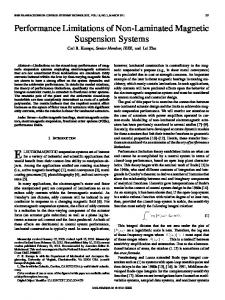
Fig. 9. Bode diagrams of the sensitivity function (full line) and the complementary sensitivity function (dashed line).
to the slow zero was also well-known in the typical dipole pattern that was recommended in classical servo systems, see Truxal (1955).
6.3. Design Rules We thus find that the closed-loop poles should be chosen carefully in a pole-placement design. Based on the insight derived from the examples the following rules can be suggested: • For minimum phase systems which have zeros that are slower than the dominant closed-loop poles we should position additional closed-loop poles which are slightly faster than the process zeros. If there are open loop poles that are significantly faster than the dominant poles we should position additional closed-loop poles that are slightly slower than the fast poles. This means that there are controller poles close to the zeros. In such a case a two-degree of freedom configuration should be chosen so that the slow controller poles are not excited by set point changes. • For non-minimum phase systems the design ineq ualities should be used to select the dominant closed-loop poles. Slow unstable zeros and fast unstable poles impose severe limitations on what can be achieved.
Even if we have focused on the pole-placement design method, similar phenomena occur for other design techniques. There is no way to avoid the fundamental limitations and their consequences for design.
7. Conclusions In this paper we have formulated and solved several problems that make it possible to estimate the limitations on control-system performance that are imposed by measurement noise, actuator saturation, and singularities of the transfer function in the right half plane . For minimum phase systems the crossover frequency is given by Eq. (12). For non-minimum phase systems the crossover frequency is instead determined by Eq. (16) which implies that the minimum phase part of the open loop transfer function at w gc has a phase lag in the range of 7r/4 to 7r/2. From these conditions it is possible to derive simple design rules. The results can be taught in elementary courses in feedback control. The consequences of making designs without considering the limitations have been illustrated.
8. References Anderson BDO, Moore JB. Optimal control linear quadratic methods. Prentice Hall. Englewood Cliffs, NJ 1990 ASlrom KJ Reg1erteori. (Contr~1 Theory). (In Swedish). Almqvisl & Wiksell. Uppsala. Sweden 1968
Limitations
0/1
Control Systcm Pcr!iml1ancc
Astrom KJ. Autonomous controllers. Control Eng Practice 1993; 1:2: 227-232 Astrom KJ. Fundamental limitations of control system performance. In Paulraj et al. (Eds) Mathematical Engineering: A Kailath Festschrift. Kluwer, 1996 Astrom KJ, Wittenmark B. Adaptive Control, second edn. Addison- Wesley, Reading, Massachusetts 1995 Bode HW, Network Analysis and Feedback Amplifier Design. Van Nostrand, New York 1945 Bongiorno Jr. JJ, Youla DC. On observers in multi-variable control systems. International Journal of Control 1968; 8(3): 221-243 Bongiorno Jr. JJ, Youla DC. Discussion of 'on observers in multivariable control systems' correspondence. International Journal of Control 1970; 12(1): 183-190 Boyd S, Desoer CA. Subharmonic function and performance bounds in linear timeinvariant feedback systems. IMA J Maht Contr and Info 1995; 2: /53-170 Boyd SP, Barratt CH. Linear controller design limits of performance. Prentice Hall Inc., Englewood Cliffs, New Jersey 1991 Chen J. Sensitivity integral relations and design tradeoffs in linear multivariable feedback systems. IEEE Transactions on Automatic Control 1995; AC-40(10): 17001716 Chen J. Multivariable gain-phase and sensitivity integral relations and design tradeoffs. IEEE Transactions on Automatic Control 1998; AC-43(3): 373-385 Clarke R, Burken JJ, Bosworth JT, Bauer JE. X-29 flight control system: lessons learned. International Journal of Control 1994; 59(1): 199-219 Doyle JC, Francis BA, Tannenbaum AR. Feedback control theory. Macmillan, New York 1992 Doyle JC, Stein G. Multivariable feedback design: Concepts for a classical/modern synthesis. IEEE Transactions on Automatic Control 1981; AC-26: 4-16 Engell S. Optima le lineare regelung. Springer. Berlin 1988 Francis BA, Glover K. Bounded peaking in the optimal linear regulator with cheap control. IEEE Transactions on Automatic Control 1978; 23(4): 608-617 Francis BA, Zames G. On Hoc optimal sensitivity theory for SISO feedback systems. IEEE Transactions on Automatic Control 1984; AC-29( I): 9-16 Frank PM. Vollstiindige Vorhersage im stetigen Regelkreis mit Totzeit, Teil I. Regelungstechnik 1968a; 16(3): /11/16 Frank PM. Vollstiindige Vorhersage im stetigen Regelkreis mit Totzeit. Teilll. Regelungstechnik 1968b; 16(5): 214218 Freudenberg JS, Looze DP. Right half plane pole and zeros and design tradeoffs in feedback systems. IEEE Transactions on Automatic Control 1985; AC-30: 555-- 565 Freudenberg JS, Looze DP. A sensitivity trade-off for plants with time delay. IEEE Transactions on Automatic Control 1987; AC-32: 99--104 Freudenberg JS, Looze DP. Frequency domain properties of scalar and multivariable feedback systems. Springer Verlag, Berlin 1988 Goodwin G, Mayne DQ, Shim J. Tradeoffs in linear filter design. Alltomatica 1995; 31(10): 1367-1376 Graebe SF, Middleton RH. Stable open loop poles: to cancel or not to canceP In: Proceedings of the 34th IEEE conference on decision and control. New Orleans. LA 1995 Green M. Limebeer DJN. Linear robust control. Prcntice Hall. Englewood Cliffs. NJ 1995
19
Havre K, Skogestad S. Achievable H x-performance of multivariable systems with unstable zeros and poles. In: Preprints 14th triennial IFAC world congress, vol. D, pp. 391- 396. Pergamon, Beijing 1999 Horowitz IM. Synthesis of feedback systems. Academic Press, New York 1963 Horowitz IM. Quantitative Feedback Design Theory (QFT). QFT Publications, Boulder, Colorado 1993 Horowitz IM, Shaked U. Superiority of transfer function over state-variable methods in linear time-invariant feedback system design. IEEE Transactions on Automatic Control 1975; AC-20: 84-97 Huang CV, Knowles GA. Application of nonlinear control strategies to aircraft at high angle of attack. In: 29th IEEE . COJiference on Decision and Control, pp. 188-193. Honolulu, Hawai 1990 Keel LH, Bhattacharyya SP. Robust, fragile, or optimal? IEEE Transactions on Automatic Control 1997; AC42(8): 1098-1105 Khargonekar P, Tannenbaum A. Non-euclidean metrics and the robust stabilization of systems with parameter uncertainty. IEEE Transactions on Automatic Control 1985; AC-30(10): 1005-1013 Klein RE. Using bicycles to teach system dynamics. IEEE Control Systems Magazine, CSM 1986; April, 4-9 Kwakernak H. Optimal low-sensitivity linear feedback systems. Automatica 1969; 5: 279-285 Kwakernak H. Symmetries in control system design. In: Isidori (Ed.), Trends in control - a european perspective. Springer, Berlin 1995 Kwakernak H, Sivan R. The maximally achievable accuracy of linear optimal regulators and linear optimal filters. IEEE Transactions on Automatic Control 1972; AC-17(1): 79-85 Maciejowski JM. Multivariable feedback design. AddisonWesley, Reading, Massachusetts 1989 Middleton JM. Trade-offs in linear control system design. Automatica /991; 27(2): 281-292 Mita T. On zeros and responses of linear regulators and linear observers. IEEE Transactions on Automatic Control 1977; AC-3I(10): 423-439 Morari M, Zafiriou E. Robust process control. Prentice Hall, Englewood Cliffs, New Jersey 1989 Newton Jr., GC, Gould LA, Kaiser JF. Analytical design of linear feedback controls. John Wiley & Sons 1957 Qiu L, Davison El. Performance limitations of non-minimum phase systems in the servomechanism problem. Automatica 1993; 29(2): 337 -349 Seron MM. Braslavsky JH, Goodwin Gc. Fundamental limitations in filtering and control. Springer, Berlin. 1945 Skogestad S, Postlethwaite I. Multivariable feedback control: analysis and design. Wiley, Chichester, UK 1996 Stein G. Respect the unstable - the 1995 bode lecture. In: 30th IEEE conference on decision and control. Honolulu, Hawai 1990 Sussman HJ, Kokotovic PV. The peaking phenomenon and the global stabilization of nonlinear systems. IEEE transactions on automatic control 1991; AC-36(4): 424-439 Truxal J. Automatic feedback control system synthesis. McGraw-Hill. New York 1955 Yaniv 0, Glltman P-O, Chepovetsky I. Sensitivity reduction limitations in mimo non-minimum phase feedback systems. In: Preprints 14th triennial IFAC world congress, vol. D. pp. 417 424. Pergamon, Beijing 1999
20
Youla DC, Jabr CN, Lu HA. Single-loop feedback stabilization of linear multivariable dynamical systems. Automatica 1974; 10(2): 159-173 Zames G. Feedback and optimal sensitivity: model reference transformations, multiplicative semi norms, and
K.J. ASIr