Line matching schemes in binocular and trinocular vision [1, 2, 3, 6, 7, 8] have been primarily ... between views is small, while point-based matching is not robust as occlusion ... constraint is also used in this step. Note that they are applied with loose thresholds so that they throw out wrong matches but retain the subset that.
Line Based Trinocular Stereo D. Yang and J. Illingworth Dept. of Electronic and Electrical Engineering, University of Surrey, Guildford, Surrey GU2 5XH, United Kingdom Abstract An approach to solving the stereo correspondence problem in trinocular stereo vision is described. It is based on geometric matching constraints relating the orientation of lines extracted in three images taken from different viewpoints. These novel constraints are termed unary orientation and binary orientation constraints. Matching is achieved within an optimisation framework in which the constraints are encoded into a cost function that is optimised using the simulated annealing method. Results are demonstrated and the characteristics of the approach are explored on both synthetic and real1 trinocular images.
1
Introduction
A fundamental problem in computer vision is the inference of 3D structure from 2D images. An important machine vision technique for this is stereo vision. In stereo vision several images of a scene are taken from different viewpoints and an attempt is made to find the correct correspondence of image features that are projections of the same physical entity. If the geometric relationship between viewpoints is well known then accurate 3D structure can be recovered using the measured image disparity (or shift) between matched features. The problem addressed in this paper is that of finding the correct feature correspondences in a set of three stereo images. Previous work in stereo vision has involved matching of point or line features. Line matching schemes in binocular and trinocular vision [1, 2, 3, 6, 7, 8] have been primarily based both on similarity of feature attributes and on using pointbased representations of lines (midpoints or endpoints) that allow adoption of epipolar constraints developed for point based stereo matching. Unfortunately, matching based on similarity of features is limited to cases where the angle between views is small, while point-based matching is not robust as occlusion effects or line fragmentation artifacts mean that midpoints or endpoints may not correspond to the same 3D point in a scene. In this paper we attempt to exploit fully the geometric constraint information inherent in lines among three views. We suggest more direct geometric constraints based on the relationship between the orientation of lines in three distinct images. Two main results are exploited: the first uses the orientation 'The real trinocular data was kindly supplied by Dr N. Ayache of INRIA, Rocquenfort, France and is the data used in his recent book "Artificial Vision for Mobile Robots: stereo vision and multisensory perception" BMVC 1992 doi:10.5244/C.6.34
328
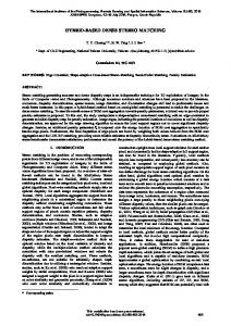
stepl:
Line detection
and
Lint grouping II (line.)
I2(linet)
Dfline.) Step2: Pruning nulcha by (1) buckets, sunfarily of lines (2) weak unary orientation constraint
Possible Macheslij.kl ( i i n U J i n Q . kinD)
Step3: Set coat function by (1) unary orientation constraint (3) binary orientation constraint
Step4:
Minimise coat luncuon by ing
Matching of linea
Figure 1: Overview of the Algorithm of lines in three images and is called the unary orientation constraint while the second constraint relates pairs of lines matched in three images and is called the binary orientation constraint. These constraints are viewpoint independent and it is the distinctive feature of our method. These constraints are encoded into an optimisation matching algorithm. An overview of the proposed algorithm is shown in Figure 1. Lines segments are extracted in three images taken from different viewpoints. Segments which are collinear are grouped into a single line as our algorithm primarily uses only orientation information. Each line segment is represented by an N-vector [4], which is the unit normal to the plane that contains the image line and the optical centre of the viewing camera. The second stage of the algorithm is a simple pruning step that discards inadmissible matches using heuristics such bucketing of lines and line similarity information which are commonly used by other authors [1, 2, 3, 6, 7, 8]. In addition, the proposed weak unary orientation constraint is also used in this step. Note that they are applied with loose thresholds so that they throw out wrong matches but retain the subset that includes the correct matches. The objective of the second stage is to quickly reduce the size of the matching problem. In the third step of our method the proposed unary and binary orientation constraints are encoded into a cost matching function. The configuration of matches represented by the minimum of the cost function correspond to the best correspondence of the image lines. Any suitable optimisation algorithm could be used for minimisation but in this work we have used simulated annealing in order to find a global minimum. The computational cost of the process kept manageably low as the number of matches has been reduced by the preceding grouping and pruning stages. The rest of the paper is organised as follows: section 2 discusses in detail the geometric constraints for the orientation of lines viewed from three different views and derives the unary and binary constraints. Section 3 shows how the constraints may be encoded into a matching cost function and briefly discusses the simulated annealing method that is used tofindthe minimum cost solution. Section 4 shows experimental results of tests of the algorithm on both real and synthetic data while Section 5 summarises the contribution of the work and offers suggestions for its future development.
329
2
Line Orientation Constraints
In this section, the representation of 2D and 3D lines is considered and the relation between 2D lines and 3D lines is established. Geometric constraints for orientation of lines among three different views are explored. Two kinds of orientation constraints for matching lines in three images are introduced: unary and binary orientation constraints. The camera model used is the pinhole model and perspective projection is adopted as the model of the image formation process. The relation between a 3D point and its 2D projection is expressed by the following:
=T where (u, v) are image coordinates, w is a scalar, (x, y, z) are 3D point coordinates, T is a 3 x 4 matrix called the perspective transformation matrix and is defined up to a scale factor. Points and lines in the image plane are represented (uniquely up to a sign) by unit vectors of homogeneous coordinate called N-vectors [4]. The unit vector starting from the optical center and pointing toward a point P in the image plane is called the N-vector of point P. The unit vector normal to the plane passing through the optical center C and intersecting an image plane along a line 1 is called the N-vector of line I. Figure 2(a) shows an example of representation of a point and a line by N-vectors. For 3D vectors o, 6 and c the following notations are used throughout the paper: a.b denotes the inner or dot product, a x b denotes the cross product, < a,b,c > = (a x b).c = (6 x c).a = (c x a).b denotes the scalar triple product, [a] = a/\\a\\ denotes the normalization of vector a and ||a|| denotes the norm of vector a. The N-vector, m, of a point P(u, v) can be obtained from the perspective projection matrix T as m = [(