Larry S. Davis. Department of Computer Science,. University of Maryland,. College Park, MD 20742, USA ... cost is found using dynamic programming and the dispar- ity filled along .... section, we illustrate how the best path can be recovered.
Trinocular Stereo using Shortest Paths and the Ordering Constraint Motilal Agrawal and Larry S. Davis Department of Computer Science, University of Maryland, College Park, MD 20742, USA email: mla,lsd @umiacs.umd.edu �
Abstract This paper describes a new algorithm for disparity estimation using trinocular stereo. The three cameras are placed in a right angled configuration. A graph is then constructed whose nodes represent the individual pixels and whose edges are along the epipolar lines. Using the well known uniqueness and ordering constraint for pair by pair matches simultaneously, a path with the least matching cost is found using dynamic programming and the disparity filled along the path. This process is repeated iteratively until the disparity at all the pixels are filled up. To demonstrate the effectiveness of our approach, we present results from real world images and compare it with the traditional line by line stereo using dynamic programming. Keywords: computer vision, trinocular stereo, dynamic programming, ordering constraint
1. Introduction Establishing correspondences is the key problem in 3D reconstruction from stereo images. The goal of correspondence is to assign matches to each point in the reference image. This is done using a measure of similarity based on the intensities at the points. Stereo correspondence methods may be either feature based or pixel based. In feature based correspondence methods, features such as intensity edges are extracted and matched first. The similarity measure used in this case are correlation windows centered around the features [10]. Subsequently, correspondence for the remaining points is determined by interpolation and knowledge of scene geometry. Pixel based correspondence methods directly find the correspondence for each pixel using the pixel intensities. Lately, pixel based correspondence methods have gained popularity[7, 3, 14]. Pixel based methods have the advantage of giving dense depth maps. When combined with additional constraints and assumptions about the scene, it can yield very accurate results.
One such widely used and well understood constraint is the epipolar constraint. The epipolar constraint arises from the geometry of the cameras. This constraint restricts the match of a point in the reference image to lie along the epipolar line in the other image. It reduces the search space to a line but the problem still remains intractable because of the exponential size of the search space. This has made it necessary to use additional assumptions about the nature of the scene. Ohta & Kanade and Cox et al. [11, 7] make the uniqueness and ordering assumption. Uniqueness states that each point in the reference image has a unique match, and the ordering constraint requires that the order of matches is preserved along corresponding epipolar lines. Under these additional assumptions, the correspondence problem can be solved efficiently using dynamic programming for each epipolar line. The ordering constraint is based on the physical assumption that scenes are smooth along epipolar lines. Such scenes would not only be smooth along epipolar lines, but also across epipolar lines. Therefore the matches on adjacent epipolar lines are not independent. Ohta and Kanade [11] address this issue for the case of feature based correspondence by extracting connected edge segments and performing an elegant 3D dynamic programming. Agrawal et al [2] formulate the problem as a two stage dynamic programming. In the first stage, dynamic programming is used to obtain ’K’ best solutions for each scanline. In the second stage another search is performed to find solutions for each row with maximum smoothness between adjacent epipolar lines. Roy & Cox, Ishikawa & Geiger [14, 9] have generalized the one dimensional ordering constraint to a two dimensional local cohesivity constraint and formulated the problem as finding a minimum cut through a graph. The local cohesivity assumption means that the disparities tend to be locally similar in all directions and thus across epipolar lines as well. However this generalization ignores the stronger epipolar constraint. More recently, Zabih et al. [6] have used graph cuts to find local minimum (in a strong sense) of energy functions that preserves discontinuity and
applied it to a pair of stereo images. In this paper, we address the issue of interaction between epipolar lines through the addition of one more camera. Using this trinocular camera configuration we formulate the problem as a shortest path problem and solve it efficiently using dynamic programming techniques. One of the key features of our formulation is that it allows us to consider the uniqueness and the ordering constraint in a three camera setup. Trinocular stereo, and in general multiview stereo, has been studied before. In [12], the matching is done separately on the two pairs of images and the results are merged using relaxation. [15] introduces additional trinocular constraints and combines the views using a connectionist network relaxation algorithm. In [13], feature based matching across three widely separated views is performed which simultaneously outputs the trifocal tensor[8] between the views. Point features such as corners are determined and matched across the views using a local correlation based similarity measure augmented with a local homography estimation. The homography provides the map between interest point neighborhoods for the cross correlation affinity measure and small baseline stereo can then be subsequently applied. This is then used to estimate the trifocal tensor. However, for our algorithm, we assume that the cameras are already calibrated and thereby the trifocal tensor and also the camera matrices are known. The organization of the rest of the paper is as follows. Section 2 describes the geometry of the trinocular stereo and section 3 presents the outline of the algorithm. The formulation of trinocular stereo as a shortest path problem is presented in section 4. In section 5 we present the results of our algorithm on real images and compare it with a standard widely used stereo algorithm based on dynamic programming on single scan lines .
P
t
top image (It)
p r C center image (Ic)
right image (Ir)
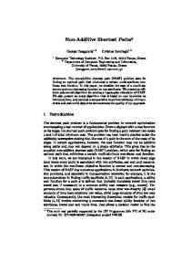
Figure 1. Trinocular Stereo Geometry camera center to the point on the image plane. The � point
can then be projected in the right and top cameras to give the image points � and � respectively. In the absence of full calibration, the trifocal tensor [8] can be computed from a few known matches in the three images which can then be used to transfer point correspondences between the center and the right image to the top image. In either case, the fundamental matrices for the image pairs can then be easily recovered. Under the assumption that the image intensity is independent of the viewing direction (i.e. the surface is lambertian), the pixel intensities at points , � and � in the center, right and top images should be identical. ���
2. Trinocular Stereo Framework
� ����
�
� �������
�
������
Therefore we define the error in matching ��� ������ as Figure 1 shows the trinocular stereo configuration used. The three cameras are placed on the vertices of a right angle triangle. This ensures that the epipolar lines for the center image corresponding to the right and the top cameras are mutually perpendicular. Each point in the center image ����� has disparities ��� and � with reference to the right and top cameras respectively. Since, in this “ideal” case the baseline distances of the top and the right camera relative to the center camera are the same, the arrangement does not increase the accuracy of the disparity of the points but helps in reducing the error. Hence it does not matter whether we refer to disparity ��� or � . For the remainder of the paper, � will denote the disparity with reference to the right camera. We assume that the three cameras are fully calibrated, so that each disparity value � of a pixel in the center image corresponds to a � location, , on the line joining the
��� �������� "$#!%
��� ����!������� ��� � ��� ��& � ��(' � ������& �)& � ��(' �
�������& �
(1)
This error function can be used to perform the matching and ideally it will be zero for a correct match. Note that since we project the � point in all the three views, the cost function takes account of all the three views simultaneously. This formulation assumes that the point is visible in all the three images. If the point is occluded in one or more of the three views, then the error will be large. In that case, the point will be null matched(occluded) by this cost function. Formulation of an error function for multiple views is challenging due to the presence of occlusions[1]. In this paper, we use the simple formulation for error function above and focus on control issues in trinocular stereo.
3. Algorithm Outline
2. Obtain the matches for points on this path Since the goal of the correspondence search is to minimize the overall error in matching, this criteria can be used to recover the best path also. Therefore the best path is the path along which the error of matching is minimum. In the next section, we illustrate how the best path can be recovered using dynamic programming in 3D.
4. Shortest Path Formulation
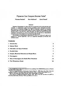
Figure 2. Central Image - Test set 0 Figure 2 is the central image from our trinocular stereo setup. The epipolar lines in the center image for the right and top cameras are also marked at the image boundaries. Although our implementation does not require the epipolar lines to be exactly horizontal or vertical(which is hard to achieve), in the discussions below, to simplify the exposition, we will assume that the epipolar lines in the center image for the right and top cameras are horizontal and vertical respectively. Suppose a point in the center image matches a point in the right image and let � be the corresponding point in the top image. Let �� be a point to the left of on the same row and (� be to right of . Also let
� be a point above in the same column and �� be below
. Then by the ordering constraint 1. Along the horizontal epipolar line, �� can have a match only to left of in the right image and (� can match to a point to the right of . 2. Similarly for the vertical direction, matches for the points � and �� must respectively lie above and below � in the top image. Matching the horizontal or the vertical epipolar lines independently ignores the ordering constraint in the other direction. Therefore the horizontal and vertical epipolar lines should not be matched independently. Instead, we propose to match along an interleaving path through the image consisting of horizontal and vertical epipolar lines. The horizontal ordering constraint will be preserved along the horizontal portions of the path and the vertical ordering constraint will be preserved along the vertical portions. Thus there are two subproblems 1. Identify the path along which to compute disparities
In order to find the shortest path, we treat the center image as an undirected graph. The individual pixels form the nodes of this graph. The edges of this graph link each node ����� � � to its four neighbors. Note that all the three points ��� '�
� � � , ����� � � and ��� �
� � � lie on the horizontal epipolar line. Similarly the points ����� � '� )� , ����� � � and ����� �� � )� lie on the vertical epipolar line. We also need to identify the origin and destination nodes so as to define the endpoints of the path we wish to find. The point ��� ��� � is taken as the origin and all the points on the last row and last column are the destination nodes. If there are disparity levels, each point � ����� � � in the center image has possible disparities ��� � ����� � ������������� ����� ����� � . Corresponding to each disparity � � � , we have an error ��� ���� � � � , which is the cost of assigning disparity � � � to . This error is computed using equation 1. In addition may be occluded in one or more views, we denote this by ���! and the corresponding cost by "$#%# . Similarly for points in the right and top images, let "$#%#'& and "$#%#'( be the cost of their being occluded. Let )�� ��� '�
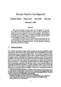
� � � and � � ����� � '* )� . Refer to figure 3. We can arrive at either horizontally from ) or vertically from � , which corresponds to a horizontal and vertical edge respectively. Consider the horizontal edge from ��)����,+ -�� to � ���� � � � This edge is valid if it preserves the horizontal ordering constraint in the right image. i.e. the projection of the 3D point ��)���� + -�� lies to the left of the projection of the 3D point corresponding to � ������ � � in the right image. In figure 3, the edge ��)�����.- � is invalid. Similarly the vertical edge from ���!��� + � � is valid if it preserves the vertical ordering constraint in the top image. Each edge has a cost associated with it. Let � �,/�01& ��)����$+ -!� ���� � � � be the cost of the horizontal edge from ��)���� + - � and � �,/�0,( ���!��� + � � ������ � � the cost of the vertical edge. They are defined as
243�5�687 9 ��)���� + -!� ������� ��� ��� ������ � �: & ��� � ' = 243�5�6A@ 9
+ ��� ��� ��� ������ � : � & ��� � ' = ���!��� � � ����
�
+ - '& ;