International Journal of Applied Engineering Research ISSN 0973-4562 Volume 10, Number 24 (2015) pp 45675-45683 © Research India Publications. http://www.ripublication.com
LINEAR BINARY PATTERN BASED BIOMETRIC RECOGNITION USING HAND GEOMETRY AND IRIS IMAGES Mr. S.Velmurugan#1 Assistant Professor Department of Electrical and Electronics Engineering, KSR Institute for Engineering and Technology Tiruchengode, Namakkal Dt
[email protected]
Abstract- Biometric recognition is an emerging technology that can be used to resolve the person identity related security issues. This work considers the problem of strengthening security level and also avoids the denial of service. The proposed system gets the input image as Hand Geometry and Iris image. Median filter is used to perform the pre processing. Discrete curvelet transform is used to perform the image enhancement. Thresholding technique is used to segregate foreground object. Then Linear Binary Pattern (LBP) is used to extract the unique feature. The extracted feature is stored to database. The real time comparison is made with feature stored database. Finally result is either accepted or rejected with quick response. The input images are collected from standard database as CASIA Iris Image Database Version 4.0, CASIA Hand geometry Image Database and comparison is made with existing system. The application areas are security and surveillance systems, gaming, human-computer interaction systems etc. Keywords: Linear Binary Pattern, Discrete Curvelet Transform, Median filter, Thresholding technique
Introduction Identification and verification are two general biometrics uses which require reference data that a person’s measured traits are compared to reference templates or raw data. During such processes, biometric data sample is compared with respective biometric data of a person in a database or against a person’s reference template to confirm his/her identity. When a biometric system identifies a person correctly, then identification result is a true positive and if it rejects a person for not matching the enrolled template, it is a true negative result [1]. Biometric authentication technologies like face, finger, hand, iris, and speaker recognition are commercially available and in use [2]. A biometric system is a pattern recognition system operating by acquiring an individual’s biometric data, extracting a feature set from learned data, and comparing this against a database template. Depending on context, a biometric system operates in verification or identification modes [3]. This proposed model is more advanced than unimodal where it combines the hand geometry and iris image.
45675
Dr.S.Selvarajan *2 Principal Muthayammal College of Engineering Rasipuram, Namakkal Dt
[email protected]
Overview The proposed system gets the input image as hand geometry and Iris image which is a bio-model one where hand geometry and iris are combined together. Median filter is used to perform the pre-processing. Discrete curvelet transform is used to perform the image enhancement. Thresholding technique is used to segregate foreground object. Then Linear Binary Pattern (LBP) is used to extract the unique feature. The extracted feature is stored to database. The real time comparison is made with feature stored database. Finally result is either accepted or rejected with quick response.
Related Work Unimodal biometrics have problems like noisy data, nonuniversality, intra class variation inter class similarities and spoofing which make the system less accurate and secure. To offset them and increase security, multimodal biometrics are used. Multimodal biometrics use multiple information sources for personal authentication. They are popular now as it is at the front of unimodal biometrics [4]. Biometric systems are unimodal when used in real world applications [5]. They rely on a single source of information for evidence for authenticating a person. Disadvantages of Unimodal Biometrics are: • Noisy data: - biometric sensors susceptibility to noise results in inaccurate matching, as noisy data leads to false rejection. • Intra class variation: - biometric data acquired in verification will not be identical to data used to generate template during individual enrolment. This is intra-class variation and they increase a biometric system’s False Rejection Rate (FRR) • Interclass similarities: - refers to feature spaces overlap corresponding to multiple individuals. They increase a biometric system’s False Acceptance Rate (FAR). • Non universality: -Some people cannot provide required standalone biometric, due to illness/disabilities [5]. • Spoofing: - Unimodal biometrics is susceptible to spoofing where the data is imitated/forged. Hand geometry-based authentication is effective in biometrics. All working populations have hands, and excepting processing for disabled people, can be engineered.
International Journal of Applied Engineering Research ISSN 0973-4562 Volume 10, Number 24 (2015) pp 45675-45683 © Research India Publications. http://www.ripublication.com Hand geometry measurements are collected easily collected due to hand dexterity and a simple method to sense which imposes no undue requirements on imaging optics. Hand geometry-based verification system is efficient for various reasons. Data to identify a user in a system is very less; so many templates are easily stored [6]. Hand geometry systems needs only a 10 byte size template and system enrolment failure rate is very low. It is easy to use and non-intrusive. Earlier hand geometry systems were based on palm prints analysis in 2D mode. Pegs are used for proper hand placement but sometimes they create test image deformities. The Hand geometry system advantages include being a relatively simple method with low resolution images providing high efficiency with high user acceptance [7]. Hand Geometry Images are extracted from hand images captured by top mounted camera. Unlike other multi-biometrics systems, user does not undergo having to pass many sensors. With this simple acquisition, they are captured completely from verification system complexity by using top mounted single camera. Hand image segmentation is a vital step in hand biometric identification [2]. Palm feature extraction based on geometry to locate information was presented by Budi Wirayuda et al., [8]. It examined finger width, length, palm width, and ratio between middle finger length, index finger and ring finger. Combining this information resulted in palm characteristic that can recognize a person. The system’s accuracy was 88.4% using 23 palm geometry characteristics without normalization and with 0.035 thresholds on 40 individuals. Hand geometry biometrics used to find practical use across realworld security related applications was presented by Chaudhary & Sharma [9]. A hand geometry based recognition system captures a hand’s image to determine its geometry and metrics namely finger length, width and other attributes. Hand image segmentation is important in hand geometry based recognition systems as the identified feature’s accuracy was detected using a segmented hand image which is totally dependent on the segmented hand image’s quality and accuracy. A biometric recognition methodology on hand thermal information was presented by Czajka & Bulwan [10]. It also ensured a hardware presentation is designed for this research in thermal sensor plate delivering hand thermal maps, which was a greatly cheaper alternative to thermal cameras. Two different classifiers (k-NN and SVM) evaluated with a hand thermal maps database captured for 50 different individuals in 3 sessions: two on the same day (enrolment attempts), and the third a week later (verification attempt). Shape Segmentation Using Learnable Evolutionary Model and Object Identification [12] method makes use of a new technique of segmentation algorithm and it deals with basic Euclidean shapes which is a time consuming process and if it is used for segmentation technique it consumes fewer more time to authenticate. A biometric system for identification based on 3 biometric hand characteristics like palm print, Hand geometry finger surfaces and hand geometry was proposed by Ramalho et al., [11]. The authors suggested a new identification architecture using hand geometry as a soft biometric to accelerate identification and ensure system scalability. The new feature binarisation guaranteed that Hamming distance between transformed binary
45676
features was proportional to difference between their real values [15].
Proposed Work The block diagram of the proposed work is given below.
Features stored in
Real Time
Input Image: Hand Geometry, Iris Image
Input Image: Hand Geometry, Iris Image
Pre-processing using Median Filter
Pre-processing using Median Filter
Image Enhancement using Discrete Curvelet Transform
Image Enhancement using Discrete Curvelet Transform
RGB to Gray Conversion
RGB to Gray Conversion
Feature Extraction Using Segmentation, LBP, G b fil
Feature Extraction Using Segmentation, LBP, G b fil Hand Geometry, Iris Matching
Store in Database Recognition Output: Accept (or) Reject
Fig 1. Block Diagram i. Input Image The proposed system gets the input image as Hand Geometry and Iris image. The input images are collected from standard databases CASIA Iris Image Database Version 4.0, CASIA Hand geometry Image Database [14]. The sample input images are shown in figure 1.a,b,c,d.
International Journal of Applied Engineering Research ISSN 0973-4562 Volume 10, Number 24 (2015) pp 45675-45683 © Research India Publications. http://www.ripublication.com iii. Image Enhancement Using Discrete Curvelet Transform Image enhancement phase gets the input as pre processed image. Discrete curvelet transform is used to enhance the exterior edges and also improve the clarity of the image. In curvelet transform, the input image is transformed in to 2D Fourier transform. Further 2D frequency plane is divided into wedges. Then every wedge is found the curvelet co-efficient at each scale (j) and angle (theta) from the inverse Fast Fourier transform. The image enhancement output is shown in figure 3.a and 3.b.
Fig 1.a
Fig 1.c
Fig 1.b
Fig 3.a Enhanced Hand Geometry Image
Fig 1.d
iv.RGB to Gray Scale Conversion
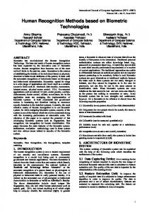
ii. Pre processing Using Median Filter The proposed system gets the input as hand geometry image and iris image. The input image has some noise due to which is infused while scanning the image because of the scanning devices. The noise causes the factor as light effects. The median filter is used to remove the noises and also smoothening the image. The pre processed output is shown in figure2.a and 2.b.
Fig 2.a Pre-processed Hand Geometry
Fig 3.a Enhanced Iris Image
Fig 2.b Pre processed Iris Image
45677
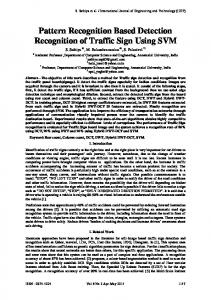
In this phase, system gets the input image as enhanced image. Color image is converted into Gray scale color space. The gray scale output is shown figure 4.a and 4.b.
Fig 4.a Gray Scale Hand Geometry image
Fig 4.b. Gray Scale Iris Image
International Journal of Applied Engineering Research ISSN 0973-4562 Volume 10, Number 24 (2015) pp 45675-45683 © Research India Publications. http://www.ripublication.com v. Feature Extraction Using LBP In this phase, the system gets the input as gray scale image. The gray scale image is converted into segmented image. The segmented image is taken into account and extract the various features are Length, Breadth, center point, Area, Perimeter, Finger Start to the reference point i.e, Distance 1,2,3,4,5 from Hand geometry and Area, Circumference from Iris and also extract the additional features as Binary patter using linear binary pattern.
Fig 6.a Segmented Hand Geometry
Fig 6.b Segmented Iris Image
Fig 6.c Binary image of Hand Fig 6.d. Feature extraction Geometry with reference point Fig 5 Hand Reference Point The white triangle in the above figure represents the reference point in the hand where from which all the lengths are calculated. Reference point is calculated using the identification of the greatest valley point in the hand and then a perpendicular line is drawn up to next edge variation. Followed by that another line is drawn parallel to x axis and it is extended up to the edge of the hand and the centre point of the line is taken as reference point. a. Segmentation Using Thresholding technique The segmentation system gets the input image as gray scale image. Here, the object of interest is Hand Geometry and iris portion and the rest of the portion are considered as background [16]. The threshold value is applied and background portion is converted into black color. The segmentation output is shown in figure 6.a and 6.b. when the threshold value is applied and the background is converted to black and remaining are converted to white then it is binary image which has only two colors and it is easy to extract the features from the binary image. Figure 6.c shows the binary image of the corresponding 6.a figure.
45678
The input image size is 2363 x 2255. The region growing algorithm is used to find the length and breadth. After that the center point is found. Then calculate the distance from finger corner to center point. The extracted feature to be represented into table and the values are represented in terms of pixel count. The lines in the Fig 6.d represent the distance features. The Extracted features are represented Table-1and Table-2.
Table-1 Feature Extraction Using Segmentation Method in Hand Geometry Features
Pixel Count
Total Pixel Count
5326310
Length
2160
Breadth
890
Center Point
X=977, Y=1470
Area
4195335
International Journal of Applied Engineering Research ISSN 0973-4562 Volume 10, Number 24 (2015) pp 45675-45683 © Research India Publications. http://www.ripublication.com Perimeter
13278
Finger corner from Center Point Distance -1
1220
Distance -2
1266
Distance -3
1306
Distance -4
1274
Distance -5
1178
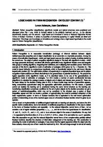
LBP Representation Using 3*3 Mask Window The input image is considered as 3*3 window mask. Each window mask the center pixel is considered as current processing pixel. The current pixel value is 6. The current pixel is compared with its neighbours. If the current pixel value 6 is greater than or equal to its neighbour, the neighbour pixel assigned the value as 1 otherwise 0. The binary pattern is formed. Then the decimal value is assigned center pixel from binary representation. The linear binary pattern representation is shown in figure7. The general form of LBP equation is represented as follows. Table -2 Feature Extraction Using Segmentation Method in Iris Image Features
No. of Pixel Count
Total Pixel Count
5326310
Area
5285759
Circumference
6736
LBP( xc , yc ) = ∑n=0 2n s(in − ic ) 7
(1)
Finally the Hand Geometry and Iris binary pattern is extracted and the output is shown in figure 8.a, b c and d.
b. Linear Binary Pattern The linear binary pattern is a texture operator. The input image is taken into 3*3 window mask. The center pixel is considered as current pixel. The center pixel is compared with its neighbours. If the center pixel value is greater than or equal to neighbour pixel value, the neighbour pixel value will be assigned as 1 other wise 0. Then the current pixel value is taken as decimal value from the binary representation. The binary pattern is represented as 8 bit. The decimal value is formed based on the first 3 bit from first row and next 3 bit from last row, last 2 bit from middle row of the 3*3 window mask.
5
5
7
18
6
3
7
2
2
Decimal: 50
0
0
1 1
Fig 8.a Segmented Image
Fig 8.b Hand Geometry LBP Pattern
1 0
0
0
Binary: 00110010
Fig 7 LBP Representation Fig 8.c Segmented Image
45679
Fig 8.d Iris LBP Pattern
International Journal of Applied Engineering Research ISSN 0973-4562 Volume 10, Number 24 (2015) pp 45675-45683 © Research India Publications. http://www.ripublication.com vi. Biometric Recognition The proposed system is extracted and all the features are stored into database. The real time comparison is made with feature stored database. Finally the biometric recognition system output is accepted or rejected. Here comparison of the entire feature one by one is not advisable which leads to computational latency. So normalization techniques are used. Min-Max normalization method is implemented in this work and all the features are converted in the range of 0 to 1. MIN-MAX Algorithm=
Si – Min value ------------------------Max value – Min value
(2)
S is the set of values for one Iris and Hand Si is ith element in the set Min value is the minimum value of the set S Max value is the maximum value of the set S Let a single row represents all the 11 features of hand geometry and Iris where there two features are combined my augmenting those values. Average of the 11 feature in a row is taken and it is maintained separately. Initial feature recognition happens with these values where the complexity is N. N is the no of persons who has to be authenticated or those images stored in the database. After finding the match in the average value the corresponding set S is retrieved from the database and the whole values are compared and authenticated.
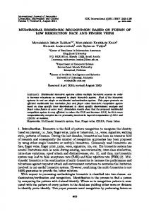
Table -3 Performance Analysis of large dataset Test Image
Total No. of Images
Correct Matchi ng
Miss Matchi ng
Accuracy Rate (%)
Hand Geometr y Image
500
470
30
94%
Iris Image
500
475
25
95%
Fusion (Hand Geometr y+Iris Image)
500
488
12
97.6%
The proposed system recognition accuracy rate is shown in Graph 1.
Results and Comparison A. Biometric Recognition Process The Biometric System Gets the Input as Hand geometry and Iris Image. The above said operations are performed and shown in the figure 10. No. Of Correct Matching Accuracy Rate(%)=................................................. *100 Total No. of Sample Space Image
(3)
The proposed system is taken the input image from CASIA Iris Image database Version 4.0, CASIA hand geometry Image database, own data and trained up to 1000 images. Accuracy rate is calculated based on Number of correct matching from total number of sample space image. The Performance of proposed system is represented in Table3. The below table shows the accuracy rate of large dataset which is taken from a standard dataset.
45680
Graph 1 Proposed System Recognition Accuracy Rate for large dataset Apurva D. Dhawale et al Method did the biometric recognition using palm print and iris images. It takes fewer parameters where the parameters are corner point and Euclidean distance. This method is only applicable for small set of database. The proposed method accuracy rate is compared with Apurva D. Dhawale et al Method. The proposed work is takes 11 features from Hand Geometry and Iris Image. It takes less computation time and also suitable for large set of databases. The performance analysis is represented in Table 4.
International Journal of Applied Engineering Research ISSN 0973-4562 Volume 10, Number 24 (2015) pp 45675-45683 © Research India Publications. http://www.ripublication.com
Input 1
Process
Hand Geometry Image
Input 2 Iris Image
Hand Geometry Image
Input Image Input Image
Pre processing Using Median Filter
Image Enhancement Using DCT
RGB to Gray Scale
Segmentation Using Thresholding
Feature Extraction
Using LBP
Biometric Recognition
Accept
Accept
Fig 10 Biometric Recognition Process
45681
Iris Image
International Journal of Applied Engineering Research ISSN 0973-4562 Volume 10, Number 24 (2015) pp 45675-45683 © Research India Publications. http://www.ripublication.com The proposed system, training Response time Recognition response time is represented in Table-5.
b. Biometric Accuracy The Biometric Recognition system gets the input image as Hand Geometry and Iris image. The accuracy rate is calculated from the number of correct matching from total number of sample space images . The Accuracy Rate (%) is represented as follows. Apurva D. Dhawale et al Method did the biometric recognition using palm print and iris images. It takes fewer parameters where the parameters are corner point and Euclidean distance. This method is only applicable for small set of database. The proposed method accuracy rate is Table -4 Performance Analysis of small dataset Test Image
Total No. of Sampl e Space
Apurva D. Dhawale et al Method [ 13]
Proposed Method
Accuracy Rate (%)
Accuracy Rate (%)
NA
Table -5 Time Complexity Analysis of Proposed System Performance
Test Image
Training Set
Hand Geometry
30s
Iris
20s
Fusion (Hand Geometry+ Iris Image)
40s
Test Set
99%
Hand Geometr y
112
Iris
42
100%
99%
Fusion
42
100%
100%
(Palm Print + Iris Image)
(Hand Geometry + Iris Image)
and
Training Response Time
Recognition Response Time
N/A
Hand Geometry
40s
Iris
35s
Fusion (Hand Geometry+ Iris Image)
50s N/A
Conclusion and Discussion
The performance analysis is compared with Existing method and it is shown in Graph 2.
The proposed system gets the input image as Hand Geometry and Iris image. Median filter is used to perform the pre processing. Discrete curvelet transform is used to perform the image enhancement. Thresholding technique is used to segregate foreground object and the given image is converted to binary image. Then Linear Binary Pattern (LBP) is used to extract the unique feature from the gray scale image. The extracted feature is stored to database. The real time comparison is made with feature stored in database. Finally result is either accepted or rejected with quick response. This method makes use of only 11 features and the comparison time and calculation time are easier. The proposed system applicable to work with large set of database and improves the person identity
References [1]
[2] Graph -2 Performance Analysis of small dataset
45682
Androunikou, V., Demetis, D., & Varvarigou, T. (2005). Biometric implementations and the implications for security and privacy. Journal of the Future of Identity in the Information Society, 1(1), 20-35. Podio, F. L. (2002). Personal authentication through biometric technologies. InNetworked Appliances, 2002. Gaithersburg. Proceedings. 2002 IEEE 4th International Workshop on (pp. 57-66). IEEE.
International Journal of Applied Engineering Research ISSN 0973-4562 Volume 10, Number 24 (2015) pp 45675-45683 © Research India Publications. http://www.ripublication.com [3] Jain, A. K., Ross, A., & Prabhakar, S. (2004). An introduction to biometric recognition. Circuits and Systems for Video Technology, IEEE Transactions on,14(1), 4-20. [4] Golfarelli, M., Maio, D., & Malton, D. (1997). On the error-reject trade-off in biometric verification systems. Pattern Analysis and Machine Intelligence, IEEE Transactions on, 19(7), 786-796. [5] Jobin, J., Joseph, J., Sandhya, Y. A., Saji, S. P., & Deepa, P. L. (2012). Palm Biometrics Recognition and Verification System. International Journal of Advanced Research in Electrical, Electronics and Instrumentation Engineering,1(2), 41-48. [6] Das, P., & Meshram, S. (2013). An efficient handgeometry system for biometric identifications. IOSR J Electron Commun Eng, 4(4), 17-9. [7] Mathivanan, B., Palanisamy, V., & Selvarajan, S. cient Hand Image Segmentation Algorithm for Hand Geometry based Biometrics Recognition System. International Journal of Computer Applications, 35. [8] El-Alfy, E. S., & Bin Makhashen, G. M. (2012, March). Evaluation of support vector machine with universal kernel for hand-geometry based identification. InInnovations in Information Technology (IIT), 2012 International Conference on(pp. 117-122). IEEE. [9] Rathgeb, C., Breitinger, F., & Busch, C. (2013, June). Alignment-free cancelable iris biometric templates based on adaptive bloom filters. InBiometrics (ICB), 2013 International Conference on (pp. 1-8). IEEE. [10] Duraipandi, C., Pratap, A., & Uthariaraj, R. (2014, April). A grid based iris biometric watermarking using wavelet transform. In Recent Trends in Information Technology (ICRTIT), 2014 International Conference on (pp. 1-6). IEEE. [12] Yano, V., Zimmer, A., & Ling, L. L. (2012, November). Multimodal biometric authentication based on iris pattern and pupil light reflex. In Pattern Recognition (ICPR), 2012 21st International Conference on (pp. 2857-2860). IEEE. [13] V. Rajasekar, S. Selvarajan, (2015), Shape Segmentation Using Learnable Evolutionary Model and Object Identification in International Journal of Applied Engineering Research Volume 10 Issue no 16 Pages 36987-36995 [14] Apurva D. Dhawale, K.V.Kale (2015),” Fusion of Iris and Palmprint Traits for Human Identification”, International Journal of Computer Techniques Volume 2 Issue 1. [15] CASIA, http://biometrics.idealtest.org [16] S.Karthiprem, S.Selvarajan, S.Sankar,” Recognizing The Moving Vehicle While Driving On Indian Roads”, International Journal of Applied Engineering Research ISSN 0973-4562 Volume 10, Number 20 (2015) pp 41471-41477.
45683