[9,18], but they require careful analysis and selection of image data in order ... the allowance of arbitrary missing data, with three points visible in all views.
Linear Multi View Reconstruction with Missing Data Carsten Rother and Stefan Carlsson� Computational Vision and Active Perception Laboratory (CVAP) Dept. of Numerical Analysis and Computer Science KTH, SE-100 44 Stockholm, Sweden Email: {carstenr, stefanc}@nada.kth.se
Abstract. General multi view reconstruction from affine or projective cameras has so far been solved most efficiently using methods of factorizing image data matrices into camera and scene parameters. This can be done directly for affine cameras [18] and after computing epipolar geometry for projective cameras [17]. A notorious problem has been the fact that these factorization methods require all points to be visible in all views. This paper presents alternative algorithms for general affine and projective views of multiple points where a) points and camera centers are computed as the nullspace of one linear system constructed from all the image data b) only three points have to be visible in all views. The latter requirement increases the flexibility and usefulness of 3D reconstruction from multiple views. In the case of projective views and unknown epipolar geometry, an additional algorithm is presented which initially assumes affine views and compensates iteratively for the perspective effects. In this paper affine cameras are represented in a projective framework which is novel and leads to a unified treatment of parallel and perspective projection in a single framework. The experiments cover a wide range of different camera motions and compare the presented algorithms to factorization methods, including approaches which handle missing data.
Keywords: Structure from Motion, Linear Multiple View Reconstruction, Missing Data, Affine and Projective Cameras.
1
Introduction
Efficient 3D reconstruction from multiple camera views is a problem of great importance in computer vision with far reaching applications. It has also received considerable attention over the years as seen from the number of publications [2, 5–7, 9–21] and books [4, 1] devoted to the topic. It is generally accepted that for parallel projection the factorization method of Tomasi-Kanade [18] is numerically the most satisfying. It is optimal under the assumption of isotropic �
This work was supported by the Swedish Foundation for Strategic Research in the VISIT program.
Gaussian noise in the image data. For perspective projection, the projective factorization of Sturm-Triggs [17, 19] has been demonstrated to be one of the most numerically efficient methods, see e.g. [5]. This method is similar to affine factorization but requires known epipolar geometry. Both these methods have a major disadvantage, however, in the fact that they require all points to be visible in all views. This of course limits their usefulness in most common multiple view situations where points eventually will be occluded as the camera viewpoint changes. Some suggestions to overcome this problem has been made [9, 18], but they require careful analysis and selection of image data in order to be used. Alternative methods for handling missing data for affine [10] and projective views [20] use the so-called closure constraints. The idea is to obtain the camera’s motion linearly and simultaneously from a series of bi- or tri-focal tensors. Ideally, an algorithm for multiple view reconstruction should utilize all available image data directly in an efficient manner. Obviously, a minimum overlap of views is necessary for the computation of relative camera positions [14]. In [15] a linear algorithm for multi view reconstruction was presented which requires four coplanar reference points to be visible in all views. All image data, except for image data from points on this reference plane, is used directly to recover points and camera centers simultaneously. The key idea is to map the reference plane to infinity which transforms the projective multi camera situation to the case of purely translating calibrated cameras. In this paper we will demonstrate that there are more multiple view situations which can be transformed to this mathematically simpler structure of translating calibrated cameras. Namely, these are exactly the cases for which affine and projective factorization can be applied: • general affine cameras • general projective cameras with known relative epipolar geometry. No assumption about the scene structure is needed. The main differences of our approach to the bilinear factorization methods are: • the selection of a finite plane as the plane at infinity • the allowance of arbitrary missing data, with three points visible in all views • the computation of the null space of one image data matrix. The fact that a finite plane will be mapped to infinity is a potential problem for numerical calculations. However, we will demonstrate practically and experimentally that this problem can be handled. Additionally, we present an iterative algorithm for the case of projective cameras and unknown epipolar geometry that initially assumes affine views and compensates iteratively for the perspective effects. A similar idea has been suggested by [4, 6, 19] to circumvent the pre-estimation of the epipolar geometry for projective factorization. In this paper affine cameras are represented in a projective framework. This is novel and leads to a unified treatment of parallel and perspective projection in a single framework.
2
Structure, Motion and the Infinite Homography
General perspective projection of a 3D point Pi onto the 2D image point pij can be described in homogeneous coordinates as: ¯ j ) Pi ∼ Hj (P¯i − Q ¯ j ), pij ∼ Hj ( I | − Q
(1)
¯ j ) represents the 3 × 4 projection matrix of camera j. Nonwhere Hj ( I | − Q ¯ j , and homogeneous homogeneous coordinates are denoted with a bar, e.g. Q coordinates without a bar, e.g. pij . The symbol “∼” means equality up to scale. Let us consider the homography Hj in more detail. A point P = (X, Y, Z, 0)T , which lies on the plane at infinity π∞ , is mapped by eqn. (1) onto the image plane πj as: X (2) pij ∼ Hj Y . Z Therefore, Hj can be considered as the infinite homography1 between the plane at infinity π∞ and the image plane πj . From eqn. (1) we see that if Hj is known, we are left with a linear and symmetric relationship between non-homogeneous points and camera centers: ¯j . p∗ij ∼ Hj−1 pij ∼ P¯i − Q
(3)
This suggests the following approach for structure and motion recovery: 1. Determine the infinite homographies Hj 2. Reconstruct points and camera centers. Section 3 will discuss several ways to determine Hj for affine views, projective views and scenes containing a reference plane. If Hj is known, eqn. (3) can be transformed into three projection relations, where the unknown scale is eliminated by taking ratios: ∗ ¯ ∗ −yij Xi + x∗ij Y¯i + yij ∗ ¯ ∗ −wij Xi + x∗ij Z¯i + wij ∗ −wij
A¯j − x∗ij A¯j − x∗ij
¯j B C¯j
∗ ¯ ∗ ¯ ∗ ¯ Y¯i + yij Zi + wij Bj − yij Cj
=0 =0
(4)
=0
∗ ∗ T ¯ ¯ i , Y¯i , Z¯i )T and Q ¯ j = (A¯j , B ¯j , C¯j )T . Therefore, with p∗ij = (x∗ij , yij , wij ) , Pi = (X each scene point P¯i visible in view j provides three linear relations of the form (4) which can be put into a set of linear equations (SLE). For n points and m views the SLE has the form (explicit in [15]):
L h = 0 with ¯ n , Y¯n , Z¯n , A¯1 , B ¯1 , C¯1 , . . . , A¯m , B ¯m , C¯m )T . ¯ 1 , Y¯1 , Z¯1 , . . . , X h = (X 1
Note, the definition of the infinite homography is slightly different to [4, 1].
(5)
The Singular Value Decomposition (SVD) of L shows that L has a four dimensional null-space. However, three of the four singular vectors of the null¯ j = (1, 0, 0)T , P¯i = Q ¯ j = (0, 1, 0)T and space have the trivial form: P¯i = Q ¯ j = (0, 0, 1)T . Therefore, the summation of all four singular vectors of P¯i = Q the null-space gives the non-trivial solution for all camera centers and points. However, points on the plane at infinity π∞ increase the dimensionality of the null-space of L (see [15]). Therefore, the projection relation of those points have to be excluded from the SLE. Since the infinite homography Hj is known, those points can be reconstructed directly with eqn. (2). How such points are detected automatically and how the SLE is formulated in an optimal way will be discussed in section 4. Let us summarize the main advantages of this approach: • One linear system containing all image data • Missing data can be handled • Points and cameras are determined simultaneously.
3
Determine the Infinite Homographies
It was shown in [15] that the infinite homographies Hj can be determined if the scene contains a reference plane visible in all views. However, in this section we will show that Hj can be determined for affine or projective cameras and general scenes without constraints on the scene structure. Additionally, for projective cameras the epipolar geometry has to be known. Let us begin with the reference plane case. 3.1
Reference Plane
In order to determine Hj , it was assumed in [15] that four coplanar scene points P1 , P2 , P3 , P4 are visible in all views. The coordinates of these reference points were chosen in a canonical way in the projective space P 3 . Furthermore, the image basis pij was mapped to the normalized projective image basis p∗ij with p1j , p2j , p3j , p4j as basis points. This corresponds to the following mapping of the reference points onto the image plane j: P1 − 1 0 0 0
P2 − 0 1 0 0
P3 − 0 0 1 0
P4 − 1 1 1 0
−→
p∗1j − 1 0 0
p∗2j − 0 1 0
p∗3j − 0 0 1
p∗4j − 1 . 1 1
(6)
We see that all the reference points lie on the plane at infinity. This means that in the particular chosen projective space, the reference plane is the plane at infinity. This transformation was noted in [21] as a fundamental requirement for obtaining the linear relationship between points and camera centers (see eqn. (3)). The infinite homography of each image j can now be derived from eqn. (2) as Hj = I. Alternatively, Hj could be derived from the inter-image homographies induced by the reference plane.
3.2
Affine Cameras P3
P4
P1 p3 p1
arbitrary plane
P2 p4
p4
p3
p2
p2
p1
eij
eji Qj
Qi
view j
view i
Affine views (a)
(b)
Fig. 1. Determine a fourth coplanar point for affine (a) and projective (b) views.
Reference plane affine view
π∞ π∞
Reference plane affine view
Fig. 2. Moving the plane at infinity π∞ from its “true” location to the reference plane.
Let us assume that three reference points P1 , P2 , P3 are visible in all views. These three points uniquely define a reference plane. The basic idea is to deduce a fourth “virtual” reference point which lies on the reference plane as well. Let us define the coplanar 3D point P4 as P4 = P3 + P2 − P1 (see fig. 1 (a)). Since affine cameras perform a parallel projection on scene points, the affine image of P4 in view j is p4j = p3j + p2j − p1j . Alternatively, the fourth point could be chosen as the centroid of the three reference points. However, how are affine cameras embedded in the projective framework derived in the previous section? Let us reconsider the mapping of a general projective camera as in eqn. (1): m11 m12 m13 m14 (7) pij ∼ m21 m22 m23 m24 Pi . v1 v2 v3 v4 The last row of the camera matrix is the principle plane πprin = (v1 , v2 , v3 , v4 )T of the camera which contains the camera center and is parallel to the image plane. In a projective space where the plane at infinity is at its true location, the principle plane of an affine camera is the plane at infinity, i.e. πprin = π∞ = (0, 0, 0, 1)T (fig. 2 left). However, we have seen in the previous section that in order to determine Hj , the reference plane has to be the plane at infinity in the particular chosen projective space (fig. 2 right). This means that in this particular projective space all camera centers lie on a plane πprin which is different to π∞ . Eqn.
(7) can now be transformed into eqn. (1) with non-homogeneous coordinates for the camera centers and scene points. From the four coplanar reference points, the infinite homographies Hj can be derived with eqn. (2) and (6). The reconstructed cameras provide the principle plane πprin , which contains all camera centers. Finally, by mapping πprin to π∞ the projective reconstruction transforms into an affine reconstruction. How does this approach compare to other affine reconstruction methods? In our approach 6 parameters of each affine camera are determined directly by the infinite homographies. The remaining 2 unknown parameters, which represent the direction of an affine camera, are reconstructed simultaneously with the scene points. In contrast to this, affine factorization [18] determines 2 parameters of each affine camera in forehand. The remaining 6 parameters of each camera are determined simultaneously with the scene points. However, this method does not allow missing data. It has been shown [6, 12] that all 8 unknown parameters of an affine camera could be determined directly by choosing a special affine basis in the scene and in the image. However, from an numerical point of view this is less favourable. 3.3
Projective Cameras
Let us assume that the three reference points P1 , P2 , P3 have canonical coordinates in the projective space and in the image as in eqn. (6). The infinite homography for each view j is then described as: aj 0 0 Hj = 0 bj 0 . (8) 0 0 1 The arbitrary scale of the matrix is fixed by setting Hj (3, 3) = 1. The variables aj and bj are unknown in each view j and can be considered as the mapping of point (1, 1, 1, 0)T into view j: Hj (1, 1, 1)T = (aj , bj , 1)T . Let us assume that the epipolar geometry is known, i.e we have the fundamental matrices between each pair of views which have at least seven points in common. We denote the epipole eij = (eijx , eijy , eijw )T as the projection of camera center j into view i (see fig. 1(b)). The inter-image homography from view i to view j via a certain plane is defined as Hij = Hi−1 Hj where Hi , Hj denote the respective homographies as defined in eqn. (1). Since the epipols between two views are in correspondence via any plane in the scene (see fig. 1(b)), we may write: eji ∼ Hij eij
⇔ Hi eji ∼ Hj eij .
(9)
Taking equation (8) and (9) we obtain two constraints between views i and j: ai ejix eijw − aj eijx ejiw = 0 bi ejiy eijw − bj eijy ejiw = 0.
(10)
All the ai ’s and bi ’s may now be determined separately but simultaneously. Each pair of images i and j, which are linked by a fundamental matrix, gives an linear
equation in ai , aj and bi , bj respectively. With m images we obtain two sets of linear equations: La ha = 0 with ha = (a1 , . . . , am )T and Lb hb = 0 with hb = (b1 , . . . , bm )T .
(11)
The last singular vector of the SVD of La and Lb gives the solution for ha and hb respectively. The vector ha and hb have an arbitrary scale which corresponds to the fact that the fourth unknown reference point on the reference plane has two degrees of freedom. The advantage of deriving the infinite homographies in this way is that all homographies are determined in one step which implies that the complete information given by the geometry is used simultaneously. 3.4
Known Structure and Cameras
For an iterative structure and motion algorithm, we would like to update the infinite homography Hj on the basis of known 3D scene points and cameras. ¯ j are known and we obtain: This means that Pi and Q ¯ j ) Pi ∼ Hj p�ij pij ∼ Hj ( I | − Q
(12)
¯ j ). Since pij and where p�ij is the projection of point Pi by camera ( I | − Q � pij are known, the infinite homography Hj can be determined for each image j individually with e. g. the normalized 8-point algorithm (see [3]). 3.5
Choice of reference points
In practice more than three points might be visible in all views of a multiple view situation. Naturally the question arises of how to find the optimal three reference points. Let us consider the criteria for good reference points. Firstly, a camera center must not lie on the reference plane. This means that the three reference points must not be collinear in any view. Secondly, in the presence of noise the infinite homography is determined more accurately if the projected reference points are far apart in the image. Since the two criteria are not contradictive, we choose as reference points those three points which are “least collinear”. This is done by considering the distance between one reference point to the line defined by the other two reference points.
4
Structure and Motion with Infinite Homographies
We have seen that with the knowledge of Hj the relationship between known ¯ j is linear (see image points p∗ij and unknown points P¯i and camera centers Q eqn. (3)). Furthermore, eqn. (3) shows that changing the image basis by a homography B and individually scaling the image points p∗ij by sij does not alter this relationship: ¯ j ∼ P¯i� − Q ¯ �j . p�ij ∼ sij B p∗ij ∼ B P¯i − B Q
(13)
How to choose B and sij in an optimal way will be discussed in this section. If B and sij are known, p�ij can be derived and we obtain a set of linear equations (SLE) as in section (2): L h = 0 with � � T ¯ 1� , Y¯1� , Z¯1� , . . . , X ¯ n� , Y¯n� , Z¯n� , A¯�1 , B ¯1� , C¯1� , . . . , A¯�m , B ¯m h = (X , C¯m ) .
(14)
Since points which are on or “close” to the reference plane potentially increase the numerical stability of the reconstruction, the projection relations of such points have to be excluded from the SLE. However, how can these points be detected automatically? One idea is to exclude successively points from the SLE which are close to the reference plane. Therefore, a ranking of all points on the basis of their distance to the reference plane has to be known. 4.1
Distance between points and reference plane reference plane π h1
h P p1 Q1
v
d
p2 baseline
reference plane π h2 P1 P2 v2
H12 p1
v1 affine camera Q1
Q2
(a)
affine camera Q2
(b)
Fig. 3. Parallax geometry for (a) projective and (b) affine cameras.
Let us consider a configuration with two cameras Q1 , Q2 , a 3D point P and a reference plane π where P does not lie on π (fig. 3(a) depicts a top view). The inter-image homography from the first to the second view via the reference is as defined in the previous section: H12 = H1−1 H2 . The residual parallax vector in the second view is given as v = p2 − H12 p1 . Obviously, v is null if P lies on π. However, v vanishes as well if P lies on the baseline of the two views. Therefore, the distance of a point to the reference plane can not be determined directly from its parallax vector. Let us define γi = hdii , where hi is the perpendicular distance of Pi to the reference plane and di is the depth of Pi with respect to the first view (see fig. 3(a)). It is known [8] that the relative depth γγ12 of two points P1 and P2 can be derived directly from their parallax vectors v1 , v2 . This means that the relative distance hh12 of two points depends on both their parallax vectors and their depths. However, if we assume parallel projection, di is constant and we obtain the relative distance of two points as: h1 v1 γ1 = = . γ2 h2 v2
(15)
Fig. 3(b) depicts a configuration with affine cameras where h1 = h2 and therefore v1 = v2 . We will use eqn. (15) as an approximation for projective cameras.
The original task was to determine a unique function dis(Pi ) which represents the distance between a point Pi and the reference plane. Eqn. (15) supplies a distance function disj1 j2 (·) between each pair of views j1 , j2 , which is unique up to scale. A unique function dis(·) can be obtained by recursively merging the set of functions disj1 j2 (·). Finally, dis(·) is scaled so that the maximal distance of a point to the reference plane is equal to one, i.e. dis(·) ∈ [0, 1]. 4.2
The choice of the image basis
It has been shown in [3] that the normalization of image coordinates can dramatically influence the result of a computation based on image coordinates. Normalization means that the centroid of all image coordinates is at the √ origin and the average distance of an image point to the origin is equal to 2. If we consider eqn. (13), normalization would involve to determine for each view j an individual matrix Bj , which represents the normalization. However, such a Bj would destroy the linear relationship between points and camera centers. Therefore, the matrix B has to be determined independently of a certain view j. We define: m � � 1 � Bj / �Bj �2 , (16) B = m j=1 � � where � · �2 is the Frobenius norm of a matrix and m is the number of views. 4.3
Weighting the set of equations
Let us consider a point P1 which is closer to the reference plane than another point P2 . Since the reference plane is the plane at infinity in the chosen projective space, the coordinates of the reconstructed point P¯1 are larger than the ones of P¯2 . This means that in the presence of noise, the point with larger coordinates is reconstructed more accurately. In order to eliminate this favoring of certain points we suggest to choose2 the scale factors in eqn. (13) as sij = dis(Pi ) where dis(·) ∈ [0, 1]. This means that points which are closer to the reference plane are inhibited. The same applies to the equations in the SLE of such a point.
5
Outline of the Algorithms
The different ideas of the previous sections result in three algorithms: A-alg. (for affine cameras), P-alg. (for projective cameras) and AtoP-alg. (an iterative version for projective cameras). The AtoP-alg. assumes initially affine cameras and compensates iteratively for the perspective effects. However, there is no guarantee that the algorithm will converge to a global minimum. The algorithms are composed of the following steps: 2
This particular choice of the scale factors sij is motivated by the mapping (0, 1)T → (1, 0)T and (1, 1)T → (1, 1)T in the projective space P 1 .
1. Detect optimal three reference points (sec. 3.5) 2. Determine Hj (sec. 3) A-alg, AtoP-alg: assume affine cameras; P-alg: assume projective cameras 3. Determine distances between points and reference plane (sec. 4.1) 4. Exclude iteratively points from the SLE 5. Determine matrix B (sec. 4.2) � � 7. Determine scales sij and image points p�ij = sij �BHj−1 pij �2 (sec. 4.3) ¯ � by SVD (eqn. (14)) and Pi on the ref. plane (eqn. (2)) 8. Obtain P¯i� , Q j 9. Only AtoP-alg.: Update Hj (sec. 3.4) and go to 3. Stop if the RMS-error is either unchanged or increases 10. Take the best result on the basis of RMS-error ¯� ¯ j = B −1 Q 11. Undo the basis change: P¯i = B −1 P¯i� and Q j The quality of the reconstruction is evaluated in terms of the Root-Means-Square (RMS) error. However, other criteria could be used.
6
Experiments Top − view
Side − view
sphere of radius 100 with 50 points
12 cameras 300
800 12 cameras 800
(a)
600
300 400
sphere of radius 100 with 50 points
(b)
Top − view sphere with 50 points
800
(c)
(d)
Fig. 4. The four different configurations: lateral movement – LAT (a), translational movement towards the scene – TOW (b), circular movement – CIR (c) and 2 images of a real sequence – TEA (d).
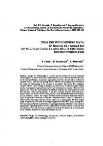
In order to demonstrate the performance of the algorithms, they were applied to a wide range of different camera motions and scene settings. Fig. 4 depicts four of them: three synthetic configurations (a-c) and a real sequence (d). Each synthetic configuration consists of 50 points distributed uniformly in a sphere
and 12 cameras pointing towards the center of the sphere. They differ in the type of camera motion: lateral – LAT (a), circular – CIR (c) and translational towards the scene – TOW (b). The distances (in units) between cameras and points are as in fig. 4. Additionally, a real sequence of 8 images (see fig. 4(d)) was utilized. The camera circled around the teapot, similar to the CIR-configuration. In order to conduct synthetic experiments on this sequence, a reconstruction of the cameras and 96 points of the teapot (see fig. 8) served as the basis for a synthetic configuration (TEA). If not stated explicitly, all the points of the TEA-configuration are visible in all views, i.e. no missing data. 6.1
Synthetic Data
The synthetic experiments were carried out with respect to different levels of Gaussian noise: σ = 0, 0.2, . . . , 3.0 (standard deviation). In order to obtain average performance, the following two steps were conducted 20 times for each noise level: a) randomly determine 50 scene points b) add Gaussian noise on the reprojected 3D points. In case of projective cameras, the internal calibration matrix was chosen as diag(500,500,1). Affine cameras were derived from the projective cameras by moving the center of projection to infinity where the image size remained fixed (see [4]). The computed reconstructions were evaluated in terms of the Root-MeanSquare (RMS) error between reprojected 3D points and 2D image data (potentially corrupted by noise). The performance of the three algorithms presented in this paper: A-alg., P-alg. and AtoP-alg. is compared to affine factorization of Tomasi-Kanade (TK-alg.) [18] and projective factorization of Sturm-Triggs (ST-alg.) [17, 19]. In [17] it is suggested to derive the initial “projective depths” from epipolar geometry. Other authors, e.g. [6, 4, 5], have shown that initialising all the “projective depths” to one and reestimating them by reprojection produce good results as well. This more simple approach was used in this paper. Different Configurations Let us consider the performance of the A-alg. and TK-alg. for different configurations (fig. 5 (a,b)). In this case, the scene is viewed by affine cameras. The performance of the TK-alg. is equally good for all configurations and close to identical with the theoretical minimum, i.e. Cramer-Rao lower bound (not shown). The differences between the results of the TK-alg. and the A-alg. are not large but noticeable. Furthermore, the A-alg. performed worse for the TOW-configuration than for the other three configurations. Since the TOW-configuration has the shortest baseline relative to the scene (see fig. 4 (b)) this result can be expected. Fig. 5 (c,d) shows the results of the P-alg. and ST-alg. with respect to different configurations. In contrast to the previous section projective cameras were used. As in the case of affine factorization, the ST-alg. is equally good for all configurations and close to the theoretical minimum. The difference between the results of the ST-alg. and the P-alg. are obvious. However, for practical noise levels, e.g. σ = 1.0, the results of the P-alg. are still acceptable. A comparison between the A-alg. (a,b) and P-alg. (c,d) shows that the results of the A-alg.
RMS error
4
5
A−alg; CIR A−alg; TEE TK−alg; CIR TK−alg; TEE
4
RMS error
5
3 2 1 0 0
A−alg; LAT A−alg; TOW TK−alg; LAT TK−alg; TOW
3 2 1
1
Noise
2
0 0
3
1
(a)
RMS error
4
P−alg; CIR P−alg; TEE ST−alg; CIR ST−alg; TEE
4
3 2 1 0 0
3
1
Noise
2
3
2
3
2
0 0
3
1
Noise
(d) 5
AtoP−alg; CIR AtoP−alg; TEE A−alg; CIR A−alg; TEE Theo. minimum
4
2 1 0 0
2
3
1
RMS error
RMS error
4
3
P−alg; LAT P−alg; TOW ST−alg; LAT ST−alg; TOW
(c) 5
2
(b) 5
RMS error
5
Noise
3
AtoP−alg; LAT AtoP−alg; TOW A−alg; LAT A−alg; TOW Theo. minimum
2 1
1
Noise
(e)
2
3
0 0
1
Noise
(f)
Fig. 5. Graphs in respect to different configurations.
are better and the curves for the A-alg. are more linear. The only difference between the A-alg. and P-alg. is the derivation of the infinite homographies. A more detailed analyses confirmed that this derivation in the case of projective cameras is fairly sensitive to noise in the epipols and reference points. Finally, fig. 5 (e,f) depicts the performance of the AtoP-alg. for different configurations with projective cameras. Additionally, the results of the A-alg. are shown, which serve as the initialisation for the iterative AtoP-alg. The theoretical minimum is displayed as well. The results of the A-alg. on the TEA-configuration were off the scale (RMS-error between 18.4 and 19.1). It stands out, that for all configurations the initial reconstruction of the A-alg. can be significantly improved by the AtoP-alg. Particularly, in the case of no noise, i.e. σ = 0, the AtoP-alg. converged for all configuration close to the theoretical minimum.
However, for higher noise levels, e.g. σ = 3.0, the AtoP-alg. did not always converge close to the theoretical minimum, e.g. TOW-configuration.
RMS error
4 3
5
A−alg; CIR A−alg; TOW TK−alg; CIR TK−alg; TOW
4
RMS error
5
2 1 0 0
3
P−alg; CIR P−alg; TOW ST−alg; CIR ST−alg; TOW
2 1
1
Noise 2 (a)
3
0 0
1
Noise 2 (b)
3
Fig. 6. Graphs for the case of perfect reference points.
Choice of Reference Points In this section we will repeat some of the experiments of the previous section. However, Gaussian noise will be added to all image points except for the three reference points. Fig. 6 depicts the results for the case of affine (a) and projective cameras (b). In contrast to the previous section, the performance of the A-alg. and TK-alg. (fig. 6 (a)) is close to identical. The same applies to the performance of the P-alg. and ST-alg. (fig. 6 (b)). Further experiments on the AtoP-alg. and other configurations confirmed this performance. This leads to the conclusion that, independent of the configuration, the choice of reference points is crucial for the three presented algorithms. Missing Data In the previous experiments was assumed that all 96 points of the TEA-configuration are visible in all 8 images, i.e. no missing data. However, in practice some points might be occluded in several views. Fig. 7 (a) shows the “true” visibility matrix of the TEA-configuration. An element of this matrix is set (black dot) if the respective point is visible in the respective view. It turns out, that 33% of the entries are not set. If the correspondence between successive frames were obtained by tracking, the final visibility matrix might look like in fig. 7 (b). Each point, except for the three reference points, is only visible in three successive views. The amount of missing data increases to 61%. If all points are visible in all views, the optimal reference points correspond to points on the body of the teapot (fig. 4 (d)). In the case of missing data (33% or 61%), points on the rim and handle were detected as the best reference points. Let us consider the performance of the A-alg. (fig. 7(d)) and the P-alg. (fig. 7 (e)) on these three types of visibility matrices: no missing data, 33% missing data (fig. 7(a)) and 61% missing data (fig. 7(b)). The first observation is that the performance of the A-alg. and P-alg. differs only slightly in respect to the different cases of missing data. Further experiments confirmed the conclusion that the performance of the three novel algorithms is “fairly” independent to the amount of missing data. A more detailed analyses shows that both algorithms performed less stable for the case of 61% missing data (zigzag shape of the
8 images
5
96 points
RMS error
(a) 8 images
Fit−alg. Closure−alg. A−alg. Theo. minimum
4 3 2 1
96 points
0 3
4
5
(b)
RMS error
4
A−alg; no mis A−alg; 33% mis A−alg; 61% mis
4
3 2 1 0 0
7
8
(c) 5
RMS error
5
6
Points per view
P−alg; no mis P−alg; 33% mis P−alg; 61% mis
3 2 1
1
Noise
(d)
2
3
0 0
1
Noise
2
3
(e)
Fig. 7. Visibility matrices (a,b) and graphs (c-e) for the case of missing data.
curves). This performance can be expected since “only” three successive views (fig. 7(b)), i.e. short baseline, provide information about the 3D position of a certain point in the scene. In the last experiment we compare the A-alg. to two alternative methods which handle missing data for affine views. Jacobs algorithm [9] fits a matrix of rank 3 to the data matrix with missing elements (Fit-alg.)3 . Kahl and Heyden [10] use the centred affine tensors between successive two and three views to obtain all camera matrices simultaneously by using the so-called closure constraints (Closure-alg.). The main advantage of these methods is that the image data is used in a uniform manner, i.e no selection of specific reference points. In contrast to our approach, the image data is not used directly to obtain structure and motion simultaneously. Fig. 7(c) shows the result for a noise level of σ = 2.0. The visibility matrix in fig. 7(b) was used, where the number of points per view varied. If a point is visible in more than 5 views the alternative methods performed slightly better, which might be due to noise in the reference points. However, in the case of more missing data, i.e. only 3 or 4 points per view, the alternative methods performed worse in this experiment. In case of the Closure-alg. an explanation might be that the data is not sufficient to obtain good tensors. 6.2
Real Data
The 8 images of the teapot (see fig. 4 (d)) served as a real image sequence. On the basis of this, 96 corresponding image points were selected manually which 3
We used the code available at http://www.neci.nj.nec.com/homepages/dwj/.
10
0 −5
−10 −10
−5
0
5
x−axis [cm] (a)
10
15
z−axis [cm]
z−axis [cm]
y−axis [cm]
15 5
10 5 0
−10
−5
0
5
x−axis [cm] (b)
10
10 5 0 −10
−5
0
5
10
y−axis [cm] (c)
Fig. 8. Top (a), side (b) and front (c) view of the reconstructed teapot (see fig. 4 (d)).
results in the “true” visibility matrix as in fig. 7 (a). The reconstruction obtained with the P-alg. had an RMS error of 2.84 between reprojected 3D points and select image points. Fig. 8 shows the top (a) side (b) and front (c) view of the reconstruction which was metric rectified. Only those scene points which lie on the contour in the top, side or front view of the teapot were reconstructed. The AtoP-alg. performed with an RMS error of 2.06 where the initial reconstruction determined with the A-alg. had a RMS error of 15.82.
7
Summary and Conclusion
We have presented two linear methods for the simultaneous computation of 3D points and camera positions from multiple affine and projective views. This is achieved by computing the nullspace of one linear system constructed from all image data. In case of affine views the only requirement is that three points are visible in all views. Additionally, for projective views the epipolar geometry has to be known. In case of unknown epipolar geometry, a third iterative algorithm for projective views has been presented. The treatment of affine and projective cameras in a single, unified projective framework is a further, novel contribution. The only other methods that use all image data directly are the factorization algorithms for affine [18] and projective [17, 19] views. However, in contrast to our approach, they require all points to be visible in all views. Since points become inevitably occluded in practice, we consider the presented methods as a major and novel contribution to the problem of structure from motion. Alternative reconstruction methods for handle missing data have been presented [9, 10, 20], which have the advantage that data is used in a uniform manner, i.e no selection of reference points. However, in contrast to our approach the image data is not used directly to obtain structure and motion simultaneously. The experiments, which covered a wide range of different camera motions and scene settings, have shown that the presented algorithms perform very well for practical noise levels. If the reference points are chosen carefully the performance of the presented algorithms compared to affine and projective factorization methods is close to identical. Furthermore, the use of all available image data, which is not available for factorization methods, is a most important numerical stabilising factor in this approach.
References 1. Faugeras, O. and Luong, Q.-T. 2001. The Geometry of Multiple Images. The MIT Press. 2. Fitzgibbon, A. W. and Zisserman, A. 1998. Automatic camera recovery for closed or open image sequences. In Europ. Conf. Comp. Vis., Freiburg, Germany, pp. 311-326. 3. Hartley, R. 1997. In defence of the 8-point algorithm. In IEEE Trans. on Pattern Anal. and Machine Intell., 19(6), pp. 580-593. 4. Hartley, R. and Zisserman, A. 2000. Multiple View Geometry in Computer Vision. Cambridge University Press. 5. Hartley, R., Dano, N. and Kaucic, R. 2001. Plane-based Projective Reconstruction. In Int. Conf. Comp. Vis., Vancouver, Canada, pp. 420-427. 6. Heyden, A., Berthilsson, R. and Sparr, G. 1999. An iterative factorization method for projective structure and motion from image sequences. In Image and Vision Computing, 17(13), pp. 981-991. 7. Heyden, A. and Kahl, F. 2000. Direct Affine Reconstruction. Int. Conf. Pattern Recog., Barcelona, Spain, pp. 885-888. 8. Irani, M. and Anandan, P. 1996. Parallax geometry of pairs of points for 3d scene analysis. In Europ. Conf. Comp. Vis., Cambridge, UK, pp. 17-30. 9. Jacobs, D. 1997. Linear Fitting with Missing Data for Structure-from-Motion. In IEEE Conf. Comp. Vis. and Pattern Recog., San Juan, Puerto Rico, pp. 206-212. 10. Kahl, F. and Heyden, A. 1999. Affine structure and motion from points, lines and conics. In Int. J. Computer Vision, 33(3):163-180. 11. Koch, R., Pollefeys, M. and VanGool, L. 1998. Multi viewpoint stereo from uncalibrated video sequences. In Europ. Conf. Comp. Vis., Freiburg, Germany, pp. 55-65. 12. Koenderink, J.J. and van Doorn, A.J. 1991. Affine structure from motion. In J. Opt. Soc. Am. A, 8(2), pp. 377-385. 13. Oliensis, J. 1995. Multiframe Structure from Motion in Perspective. In Workshop on Representations of Visual Scenes, Boston, USA, pp. 77-84. 14. Quan, L., Heyden A. and Kahl, F. 1999. Minimal Projective Reconstruction with Missing Data. In IEEE Conf. Comp. Vis. and Pattern Recog., Fort Collins, Colorado, pp. 210-216. 15. Rother, C. and Carlsson S. 2001. Linear Multi View Reconstruction and Camera Recovery. In Int. Conf. Comp. Vis., Vancouver, Canada, pp. 42-51. 16. Schaffalitzky, F., Zisserman, A., Hartley, R. I. and Torr, P.H.S. 2000. A Six Point Solution for Structure and Motion. In Europ. Conf. Comp. Vis., Dublin, Ireland, pp. 632-648. 17. Sturm, P. and Triggs, B. 1996. A factorization based algorithm for multi-image projective structure and motion. In Europ. Conf. Comp. Vis., Cambridge, U.K., pp. 709-719. 18. Tomasi, C. and Kanade, T. 1992. Shape and Motion from Image Streams under Orthography: a Factorization Method. In Int. J. Computer Vision, 9(2):137-54. 19. Triggs, B. 1996. Factorization methods for projective structure and motion. In IEEE Conf. Comp. Vis. and Pattern Recog., San Francisco, CA, pp. 845-851. 20. Triggs, B. 1997. Linear projective reconstruction from matching tensors. In Image and Vision Computing, 15(8), pp. 617-625. 21. Triggs, B. 2000. Plane + Parallax, Tensors and Factorization. In Europ. Conf. Comp. Vis., Dublin, Ireland, pp. 522-538.