International Journal of Automation and Computing
6(2), May 2009, 192-197 DOI: 10.1007/s11633-009-0192-6
Linearizing Control of Induction Motor Based on Networked Control Systems Jun Ren∗
Chun-Wen Li
De-Zong Zhao
Department of Automation, Tsinghua University, Beijing, 100084, PRC
Abstract: A new approach to speed control of induction motors is developed by introducing networked control systems (NCSs) into the induction motor driving system. The control strategy is to stabilize and track the rotor speed of the induction motor when the network time delay occurs in the transport medium of network data. First, a feedback linearization method is used to achieve input-output linearization and decoupling control of the induction motor driving system based on rotor flux model, and then the characteristic of network data is analyzed in terms of the inherent network time delay. A networked control model of an induction motor is established. The sufficient condition of asymptotic stability for the networked induction motor driving system is given, and the state feedback controller is obtained by solving the linear matrix inequalities (LMIs). Simulation results verify the efficiency of the proposed scheme. Keywords: (LMI).
1
Induction motor, feedback linearization, networked control system (NCS), network time delay, linear matrix inequality
Introduction
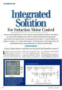
The AC motor has found wide industrial application. In an application composed of a small number of AC motors[1] , such as a conveyor belt, or a computer numerical machine milling machine, AC motors can be connected to controllers, drivers, and sensors by directly wiring these devices together to perform closed-loop control without much difficulty. Nevertheless, direct wiring is somewhat complicated and is not cost effective in the installation and maintenance of a large number of AC motors in large-scale or complex systems such as automobiles, aircrafts, and manufacturing plants. The wiring can be organized systematically by a shared data network instead of hardwired connection. Moreover, this network-based wiring provides much more modularity, remote-control capability, and ease in diagnosis for the control systems[2−4] . Conceptually, there are two approaches to utilizing a data network for the control of AC motors[5, 6] . In the first approach, each AC motor has its own controller. The controller and the AC motor are physically located close to each other. This controller receives a set point remotely from the motion controller through the network, and then uses the given set point to perform closed-loop control locally as shown in Fig. 1. A sensor measurement of the AC motor is sent back to the motion controller via the network. This approach provides modularity for each AC motor system. However, poor interaction between the motion controller and each AC motor controller is a major drawback of this approach. On the other hand, as shown in Fig. 2, the second approach uses a network as a medium to directly transfer control signals and sensor measurement between an AC motor and a controller. Closed-loop control of the AC motor is Manuscript received July 2, 2008; revised October 27, 2008 This work was supported by National Natural Science Foundation of China (No. 69774011) *Corresponding author. E-mail address:
[email protected]
communicated over the network. Each AC motor in this case is attached to a simple interface unit. This unit converts a data frame from the controller into an actual control signal and the sensor measurement into a data frame to send it back to the controller. In fact, this interface can also be thought of as a simple remote controller. Systems formulated by this approach are so-called networked-based or networked control systems (NCSs), which can provide better interaction and higher flexibility for controlling AC motors.
Fig. 1
Hierarchical control structure of AC motor via NCSs
Fig. 2
Direct control structure of AC motor via NCSs
Several standard industrial networks such as CAN, Profibus, etc.[7−9] , have been widely used for NCSs for years. The problem of how to introduce the network into
193
J. Ren et al. / Linearizing Control of Induction Motor Based on Networked Control Systems
the motor control system has attracted a lot of attention. Chow and Tipsuwan[5] designed a networked DC motor controller, and made an analytical comparison between the performance of traditional proportional-integralderivative (PID) motor control system and that of NCSs. Suh et al.[6] put forward a type of networked servo control system and developed a control arithmetic aimed at uncertain networked time delay which is known to vary in the known range. The networked control structure is more advanced because it is cheap in installation, easy to maintain and convenient for long distance control and fault diagnosis. However, the introduction of network into the motor driving system also brings many uncertain factors, such as networked time delay, loss and disorder of data packages, etc.[10] , which makes it more intricate to analyze and design the control system. This paper proposes a novel approach for networked induction motor speed control by using linear matrix inequality (LMI) method. The nonlinear model of induction motor is linearized and decoupled in the induction motor driving system using the direct feedback linear method. A networked model of an induction motor driving system with networked time delay, where the delay varies in the known range, is obtained. The sufficient condition of asymptotic stability for the networked induction motor driving system is given, and the state feedback controller is obtained on the feasible solution of the LMIs. Simulations demonstrate the effectiveness of the proposed method.
2
Induction motor modeling based on NCSs
The networked motor driving system can be divided into three parts: 1) the motor driving system; 2) the data network with time delay; 3) the networked motion controller. A general block diagram of the networked motor driving system under investigation is shown in Fig. 3. Each component is described in the following sections.
ga =
1 σLs 0 0 0 0
,
gb =
0 1 Ls 0 0 0
x = (ia , ib , ψa , ψb , ω)T
(3)
(4)
where the rotor motor speed is given by ω; the rotor fluxes are ψa and ψb ; ia , ib are the corresponding stator currents; np is the number of pairs, and J is the motor-load moment of inertia; TL is the load torque; Rs ,Rr are the stator and rotor resistances, and Rr is the rotor reference resistance; Ls , Lr are the stator and rotor self-inductances; and Lm is the stator-rotor mutual inductance. The inverse of the rotor time constant is given by α = Rr /Lr , ± and σ = 1 − L2m (Ls±Lr ) is the leakage factor. Also, γ = Rs /(σLs )+L2m Rr (σLs L2r ), β = Lm /(σLs Lr ), and µ = np Lm /(JLr ). As shown in [13–16], field oriented control can be improved by achieving exact input-output decoupling and linearization via a feedback linearization control. In this case, a solution set is φ1 (x) = ω − ωref φ2 (x) = ψa2 + ψb2 − |ψ|2ref
(5)
where ωref and |ψ|2ref are the desired reference signals. Let φ1 (x) and φ2 (x) be the output variables. The feedback linearization transformation is given by z1 = φ1 (x) = ω − ωref z2 = Lf φ1 (x) = µ(ψa ib − ψb ia ) −
TL J
z3 = φ2 (x) = ψa2 + ψb2 − |ψ|2ref z4 = Lf φ2 (x) = −2α(ψa2 + ψb2 ) + 2αLm (ψa ia + ψb ib ) (6) where Lf (·) denotes the Lie derivative with respect to f . In these new coordinates, the system equations become z˙1 z˙2 z˙3 z˙4
= z2 = L2f φ1 + Lga Lf φ1 ua + Lgb Lf φ1 ub = z4 = L2f φ2 + Lga Lf φ2 ua + Lgb Lf φ2 ub
(7)
where Fig. 3
2.1
Block diagram of the networked motor driving system
Induction motor driving system based on feedback linearization
The well-known two-phase equivalent model for an induction motor in the stationary reference frame is given by[11, 12] x˙ = f (x) + ua ga + ub gb (1) −γia + αβψa + np βωψb −γi + αβψ − n βωψ p α b b αLm ia − αψa − np βωψb f (x) = (2) αLm ib − αψb − np βωψa TL µ(ψα iβ − ψβ iα ) − J
L2f φ1 = − µβ(ψa2 + ψb2 ) − µnp ω(ψa ia + ψb ib )− µ(α + β)(ψa ib − ψb ia ) L2f φ2
= − (4α2 + 2α2 βLm )(ψa2 + ψb2 ) + 2α2 L2m (i2a + i2b )+ 2αLm np ω(ψa ib − ψb ia ) µψb , σLs
Lgb Lf φ1 =
µψa σLs
2αψa , σLs
Lgb Lf φ2 =
2αψb . σLs
Lga Lf φ1 = − Lga Lf φ2 = −
The four equations in (7) can be rewritten as ! Ã ! ! Ã Ã L2f φ1 z¨1 ua = + D(x) z¨3 L2f φ2 ub
(8)
194
International Journal of Automation and Computing 6(2), May 2009
or
and D(x) is given by " D(x) =
# Lga Lf φ1 Lga Lf φ2
Since det[D] = −
Lgb Lf φ1 Lgb Lf φ2
.
where v(t ) is piecewise continuous and only changes value at kh + τk . (10)
D(x) is nonsingular when ψa2 + ψb2 6= 0. The linearizing feedback is defined as à ! "à ! à !# ua −L2f φ1 va −1 = D(x) + . ub −L2f φ2 vb
h where z =
z1
z2
z3
z4
iT
"
# va vb
(13)
There are two sources of delays from the network: sensorto-controller τsc and controller-to-actuator τca [17] . Any controller computational delay can be absorbed into either τsc or τca without loss of generality. For fixed control law, the sensor-to-controller delay and controller-to-actuator delay can be lumped together as τk = τsc + τca for analysis purposes. We consider the setup with 1) clock-driven sensors that sample the plant outputs periodically at sampling instants; 2) an event-driven controller that can be implemented by an external event interrupt mechanism and can be used to calculate the control signal as soon as the sensor data arrives; 3) event-driven actuators, which means the plant inputs are changed as soon as the data becomes available; and 4) τmin 6 τk 6 τmax 6 h, where τmin and τmax are constant, and h is sampling period. With the above setup, it is known that within the k-th sampling period, the control signal vectors can be depicted as ( vk−1 , kh 6 t < kh + τk v(t) = (14) vk , kh + τk 6 t < kh + h and (14) can be rewritten as " # " # va ka1 z1 (k − 1) + ka2 z2 (k − 1) v= = , vb kb1 z3 (k − 1) + kb2 z4 (k − 1) if kh 6 t #< kh + τk " # " v=
=
ka1 z1 (k) + ka2 z2 (k) kb1 z3 (k) + kb2 z4 (k)
Networked motion controller
The motion controller is powerful and can provide advanced real-time control laws to the motor driving systems, including fault diagnosis and accommodation control, and network traffic condition monitoring and adaptation. The motion controller will provide the control signals va and vb to the networked motor driving system, where va is the rotor speed control signal and vb is the rotor flux control signal. According to (12) and (16), the induction motor driving system can be written as z˙ = Az + Bv, t ∈ [kh + τk , k(h + 1) + τk ] y = Cz v(t+ ) = Kz(t − τk ), t ∈ {kh + τk , k = 0, 1, 2, · · ·} (17)
|ψ|2ref ,
Data network with time delay
va vb
2.3
(12)
.
In order to track desired reference signals ωref and the input signals va and vb in (12) are designed as ( va = ka1 z1 + ka2 z2 vb = kb1 z3 + kb2 z4 .
2.2
(11)
the state space equa0 0 0 1
t ∈ {kh + τk , k = 0, 1, 2, · · ·} (16)
+
2αLm µ(ψa2 + ψb2 ) (σLs )2
The resulting system is described by tions 0 0 1 0 0 1 0 0 0 0 z˙ = z + 0 0 0 0 1 0 0 0 0 0
v(t+ ) = Kz(t − τk ),
(9)
,
if kh + τk 6 t < kh + h
where
0 0 A= 0 0
1 0 0 0
0 0 0 0
0 0 1 0 , B = 0 1 0 0
0 " 0 1 , C= 0 0 1
0 0
# 0 . 0
Sampling system (17) with period h, we obtain the closeloop system zk+1 = [Φ + (Φ1 + ∆Φ)BK] zk + (Φ2 − ∆Φ)BKzk−1 yk = Czk (18) R h−τ Rh where Φ = eAh , Φ1 = 0 max eAs ds, Φ2 = h−τmax eAs ds, R h−τk and ∆Φ = h−τmax eAs ds.
3
Controller design of induction motors via NCSs
Lemma 1. Given matrices M , N , and ∆Φ of compatible dimension with Y symmetric, then Y + N T ∆ΦT M T + M ∆ΦN < 0 holds for all ∆Φ satisfying σmax (∆Φ) 6 δ if and only if there exists a scalar ε > 0 such that Y + εN T N + ε−1 δ 2 M M T < 0. We give an estimate of ∆Φ. Lemma 2. The uncertain item ∆Φ satisfies σmax (∆Φ) 6 δ,
∀k
where (15)
0 1
δ=
eσmax (A)(h−τmin ) − eσmax (A)(h−τmax ) . σmax (A)
Proof. See Appendix A.
195
J. Ren et al. / Linearizing Control of Induction Motor Based on Networked Control Systems
Theorem 1. If there exist a positive scalar ε and positive symmetric matrices X, S, and matrix Y such that the following matrix inequality holds for arbitrary time-varying τk ∈ [0, τmax ], system (18) is asymptotically stable. −X + εδ 2 I ΦX + Φ1 BY Φ2 BY 0 (ΦX + Φ BY )T −X + S 0 Y TBT 1 < 0. T (Φ2 BY ) 0 −S −Y T B T 0 BY −BY −εI (19) Furthermore, if such a solution exists, then a suitable feedback control law for system (18) is given by vk = Y X −1 zk .
(20)
Proof. Define a Lyapunov function as T Vk = zkT P zk + zk−1 Qzk−1
(21)
where P and Q are symmetric positive matrices. ∆Vk is ∆Vk = Vk+1 − Vk .
(22)
Substituting (18) into (22), we can obtain " # h i zk T T ∆Vk = zk zk−1 Π zk−1 where
"
Π= "
G=
(23)
# −P + Q 0
0 −Q
+
GT K T B T (Φ2 − ∆Φ)T
#
−P −1 + εδ 2 I (Φ + Φ1 BK)T (Φ2 BK)T 0
Φ + Φ1 BK −P + Q 0 BK
Φ2 BK 0 −Q −BK
0 K TBT −K T B T −εI
< 0.
(27) Pre- and post-multiplying both sides of (27) by diag(I, P −1 , P −1 , I), denoting S = P −1 QP −1 , X = P −1 , Y = KX, and substituting them into (27), we obtain the matrix given in Theorem 1. ¤ To sum up, the control algorithm of the induction motor via NCSs consists of three steps: Step 1. Calculate K = Y X −1 according to LMI (19); Step 2. Calculate va and vb according to (13); Step 3. Calculate ua and ub according to (11).
4
Simulation example
Digital simulation is carried out on a 15 kW motor with rated torque 70 N·m to verify the performance of the proposed controller with Matlab. The model parameters for this motor are Ls = Lr = 0.0713 H, Lm = 0.0693 H , Rs = 0.435 Ω, Rr = 0.816 Ω, np = 2, h = 20 ms and τmax = 15 ms. The motor-load inertia is J = 0.089 kg·m2 . By solving the LMI problem in Theorem 1, we get
i
h P
Using Schur complement lemma again, we get
G
"
(Φ2 − ∆Φ)BK K = Y X −1 =
# −7.452 0
−5.183 0
0 −7.452
0 −5.183
.
Φ + (Φ2 + ∆Φ)BK.
If Π < 0, we get ∆Vk < 0, and closed-loop system (18) is asymptotically stable. According to Schur complement lemma, Π < 0 can be written as −P −1 G (Φ2 − ∆Φ)BK T −P + Q 0 G < 0. K T B T (Φ2 − ∆Φ)T 0 −Q (24) (24) can be rewritten as −P −1 Φ + Φ1 BK Φ2 BK 0 (Φ + Φ1 BK)T −P + Q + K T B T ΦT 0 −Q 2 (25) 0 ∆ΦBK −∆ΦBK T 0 0 < 0. (∆ΦBK) −(∆ΦBK)T 0 0 According to Lemma 1, denoting ∆ΦT ∆Φ 6 δ 2 I, we get 0 ∆ΦBK −∆ΦBK 0 0 6 (∆ΦBK)T T −(∆ΦBK) 0 0 2 εδ I 0 0 (26) h iT · 0 0 + ε−1 0 BK −BK 0 0 0 0 h i 0 BK −BK .
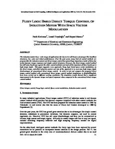
Simulated results are given for three cases, namely nominal case without time delay, nominal case with time delay and networked case with feedback controller. The simulation test involves the following operating sequences: the unload motor is required to reach the reference speed value of 110 rad/s, and changed to 220 rad/s at 6 s. At 3 s, a 40 N·m load torque, which is unknown to the controller, is applied. The well above the rotor flux amplitude reference is 1.0 Wb. The simulation of the nominal case without time delay is illustrated in Fig. 4 and that of the nominal case with time delay is shown in Fig. 5. In Fig. 4, the dynamic performances of the control law without time delay are satisfactory: no steady-state errors occur and transient responses are decoupled. However, in Fig. 5, when a time delay is inserted into the motor driving system, the performance of the control law becomes degraded. The simulation of the networked case without time delay is shown in Figs. 6 and 7. Speed behavior is shown in Fig. 6 and flux behavior is shown in Fig. 7. From Fig. 7, we know that the system is decoupled entirely. Comparing with Figs. 4–6, we can draw a conclusion that the performance of the networked case is better than the nominal case with time delay, and it can compensate for the degradation of system performance due to transport time delay for the induction motor driving system, because the time delay is considered when the networked control model is established.
196
Fig. 4 Tracking speed of the nominal motor driving system without time delay
International Journal of Automation and Computing 6(2), May 2009
Fig. 7 Tracking flux of the networked motor driving system with time delay
5
Conclusions
In this paper, a networked control scheme has been used in an induction motor based on NCS. The induction motor speed and flux are decoupled into two independent linear subsystems completely based on direct feedback linearization method, and then a networked induction motor model is obtained by considering the network time delay. Sufficient condition for asymptotical stability and the state feedback control algorithm for the system are obtained by employing Lyapunov function method and LMI theory. Moreover, the simulation results demonstrate that the induction motor driving system is decoupled completely, and the proposed scheme can obtain good performance for the networked induction motor driving systems despite the networked time delay.
Appendix A Fig. 5 Tracking speed of the nominal motor driving system with time delay
Proof of Lemma 2 Proof.
°R ° ° h−τk ° σmax (∆Φ) 6 max ° h−τmax eAs ds° 6 τk ∈[τmin ,τmax ] 2 ° ° R R h−τk ° As ° °e ° ds 6 h−τmin °eAs ° ds 6 h−τmax h−τmax 2 2 R h−τmin h−τmax
ekAk2 s ds 6
R h−τmin h−τmax
eσmax (A)s ds =
eσmax (A)(h−τmin ) − eσmax (A)(h−τmax ) . σmax (A) ¤
References
Fig. 6 Tracking speed of the networked motor driving system with time delay
[1] J. Nilsson. Real-time Control Systems with Delays, Lund Institute of Technology, Sweden, 1998. [2] W. Zhang, M. S. Branicky, S. M. Phillips. Stability of Networked Control Systems. IEEE Control Systems Magazine, vol. 21, no. 1, pp. 84–99, 2001. [3] G. C. Walsh, Y. Hong. Scheduling of Networked Control Systems. IEEE Control Systems Magazine, vol. 21, no. 1, pp. 57–65, 2001.
J. Ren et al. / Linearizing Control of Induction Motor Based on Networked Control Systems [4] F. L. Lian, J. Moyne, D. Tilbury. Network Design Consideration for Distributed Control Systems. IEEE Transactions on Control Systems Technology, vol. 10, no. 2, pp. 297–307, 2002. [5] M. Y. Chow, Y. Tipsuwan. Gain Adaptation of Networked DC Motor Controllers Based on QOS Variations. IEEE Transactions on Industrial Electronics, vol. 50, no. 5, pp. 936–943, 2003. [6] Y. S. Suh, C. W. Lee, H. H. Lee, Y. S. Ro. H2 Networked Servo Control Systems with Time-varying Delays. In Proceedings of the American Control Conference, IEEE Press, Portland, USA, pp. 644–649, 2005. [7] G. C. Walsh, Y. Hong. Scheduling of Networked Control Systems. IEEE Control Systems Magazine, vol. 21, no. 1, pp. 59–65, 2001. [8] D. D. Blair, D. L. Jensen, D. R. Doan, T. K. Kim. Networked Intelligent Motor-control Systems. IEEE Industry Applications Magazine, vol. 7, no. 6, pp. 18–25, 2001. [9] W. H. Fang, H. Cai, Q. W. Chen, H. W. Li. Stability of Networked Control System with Time-delay. Control Theory & Application, vol. 21, no. 6, pp. 880–884, 2004. (in Chinese) [10] L. A. Montestruque, P. Antsaklis. Stability of Model-based Networked Control Systems with Time-varying Transmission Times. IEEE Transactions on Automatic Control, vol. 49, no. 9, pp. 1562–1572, 2004. [11] R. Marino, S. Peresada, P. Valigi. Adaptive Input-output linearizing Control of Induction Motors. IEEE Transactions on Automation Control, vol. 38, no. 2, pp. 208–221, 1993. [12] D. I. Kim, I. J. Ha, M. S. Ko. Control of Induction Motors via Feedback Linearization with Input-output Decoupling. International Journal of Control, vol. 51, no. 4, pp. 863–883, 1990. [13] T. K. Boukas, T. G. Habetler. High-performance Induction Motor Speed Control Using Exact Feedback Linearization with State and State Derivative Feedback. Transactions on Power Electronic, vol. 19, no. 4, pp. 1022–1028, 2004. [14] C. P. Zhang, F. Lin, W. C. Song, L. W. Jiao. Nonlinear Control of Induction Motors Based on Direct Feedback Linearization. Proceedings of the CSEE, vol. 23, no. 2, pp. 99–102, 2003. (in Chinese) [15] R. J. Wai, L. J. Chang. Decoupling and Tracking Control of Induction Motor Drive. Transactions on Aerospace and Electronic System, vol. 38, no. 4, pp. 1357–1369, 2002.
197
[16] J. Chiasson. A New Approach to Dynamic Feedback Linearization Control of an Induction Motor. IEEE Transactions on Automatic Control, vol. 43, no. 3, pp. 391–397, 1998. [17] G. Xie, L. Wang. Stabilization of Networked Control Systems with Time-varying Network-induced Delay. In Proceedings of the 43rd IEEE Conference on Decision and Control, IEEE Press, Atlantis, Paradise Island, Bahamas, vol. 4, pp. 3551–3556, 2004.
Jun Ren received the B. Sc. degree in automation in 1999, and his M. Sc. degree in 2002, in process control of papermaking from South China University of Technology, PRC. He is currently a Ph. D. candidate in the Control Theory and Application Group of the Department of Automation, Tsinghua University, PRC. His research interests include networked control, motion control, and nonlinear control.
Chun-Wen Li is a professor in the Control Theory and Application Group of the Department of Automation, Tsinghua University, PRC. His research interests include nonlinear control, motion control, and electric power control.
De-Zong Zhao received the B. Sc. and M. Sc. degrees in automation from Shandong University, PRC, in 2002 and 2006, respectively. He is currently a Ph. D. candidate in the Control Theory and Application Group of the Department of Automation, Tsinghua University, PRC. His research interests include synchronized motion control and motor control.