INTERNATIONAL JOURNAL FOR RESEARCH IN EMERGING SCIENCE AND TECHNOLOGY, VOLUME-2, ISSUE-7, JULY-2015
E-ISSN: 2349-7610
Review on Field Oriented Control of Induction Motor Ayman Y. Yousef 1 and S.M. Abdelmaksoud2 1
Electrical Engineering Department, Shoubra Faculty of Engineering, Benha University, Cairo, Egypt.
[email protected] 2 Electrical Engineering Department, Shoubra Faculty of Engineering, Benha University, Cairo, Egypt.
[email protected]
ABSTRACT The field oriented control (FOC) of induction motor provide one of the most suitable and popular speed control technique presently used. The principle of field oriented control is based on the control of both the magnitude and the angle of each phase current and voltage. The control of torque is normally achieved by controlling the armature with constant field current. The Field weakening is employed to increase the speed beyond a base peed. The simplicity and flexibility of control of dc motors have made them suitable for variable speed drive applications. In the field oriented control, a d-q coordinates reference frame locked to the rotor flux vector is used to achieve decoupling between the motor flux and torque. They can be thus separately controlled by stator direct-axis current and quadrature-axis current respectively, like in a dc motor. In this paper, the principle, classification, and the most common of the field oriented control are presented. Keywords — Flux Vector, Reference Frame, FOC, Decoupling Control.
1. INTRODUCTION
change the stator frequency [3]. Since the speed is close to
The induction motor is a rugged, reliable, and less expensive
synchronous speed the operating slip is small, and slip power
ac machine. It has been the economical workhorse for use in
loss in the rotor circuit is small. However, this will require a
ac motor drive application. It has been used for both low
frequency converter, which is expensive.
performance as well as high performance drive application. It can be operate in the most adverse circumstances and giving
In drive systems, it is desired that the machine flux is
excellent service with little maintenance.
regulated to provide better utilization of the machine. A requirement for maximum possible transient dynamics is to
The closed loop control of the induction motor is normally required to satisfy the steady state and transient performance specification of ac drives. The control strategy can be implemented as follows [1]:
operate the motor at its rated flux level. Indirect flux regulation schemes such as the volt/hertz control and the slip current control use variable frequency control and have been extensively used in industry [4]. Both the volt/Hertz and
1- Scalar control: where the control variables are dc quantities and only their magnitudes are controlled. 2- Vector control: where both magnitude and phase of the control variables are controlled.
current slip frequency control provide satisfactory steady state performance. The volt/hertz control scheme is quite simple to implement. On the other hand, the current slip frequency control scheme require closed loop current regulation as well
A simple and economic method of induction motor control is to vary the stator voltage at supply frequency. This method of control is characterized by poor dynamic and static performance. Although it is inefficient because of high slip power loss [2], it is used in fans, pump, and blower drives. An
as accurate speed measurement and, therefore, is somewhat complicated to implement. However, both these methods fail to provide satisfactory transient performance. This control strategy is called "Scalar control" which employs general non vector controlled drive schemes. These include simple voltage-
efficient method of speed control for induction motors is to VOLUME-2, ISSUE-7, JULY-2015
COPYRIGHT © 2015 IJREST, ALL RIGHT RESERVED
5
INTERNATIONAL JOURNAL FOR RESEARCH IN EMERGING SCIENCE AND TECHNOLOGY, VOLUME-2, ISSUE-7, JULY-2015
E-ISSN: 2349-7610
fed and current-fed inverters. Scalar control relates to the
Resolution
1 : 1000
1 : 1000
magnitude confrol of a variable only [5]. High performance
Non-Linearity
± 12%
± 12%
drives, such as robotics, rolling mills, and machine tools
Repeatability
± 12%
± 12%
require fast and precise torque response. To achieve this, the
(Tref → Tact) 150 ms
10 to 20 ms
Resolution
1 : 20000
1: 2000
Speed Range
1 : 40
1 : 1000
± 0.01%
± 0.01%
3% sec
0.3% sec
dynamic structure of the machine has to be taken into account. The induction machine is a nonlinear multivariable highly coupled device. Several methods have been proposed to obtain fast torque response with flux regulation [6, 7]. However, the emerging consensus is to use field-oriented control (FOC).
Torque Step Rise Time Speed Control:
(Mmin / Nmax) Static Accuracy (Mact / Nref)
2. FIELD ORIENTED CONTROL The concept of field oriented control (FOC) which was introduced by Siemens company several years ago is recently receiving wide attention. This is also known as transvector control [2], because the control implementation is based on vector transformation from rotating to stationary reference frame and vice versa. The field oriented control (FOC) method permits optimum transient response of the drive and it has a good dynamic response. On the other hand, field orientation is a technique that provides a method of decomposing the stator current into magnetizing component, IM which producing the flux and
Dynamic Accuracy
Table-1: Deference between Scalar and Vector Control The performance figures listed in the table depend on the proportional gain and integration action time constant (PI time constant) set by means of parameters according to the application or process requirements. This table show that, the vector control strategy has much better performance than the scalar control method. Also several literatures such as [5, 9] show that, the vector control methods for induction motor drives allow a better dynamic performance than the scalar control method.
torque component, IT which producing the torque. These components are then decoupled and controlled individually. In
3. PRINCIPLE OF FIELD ORIENTATION
general, the magnetizing component, IM varies slowly and is
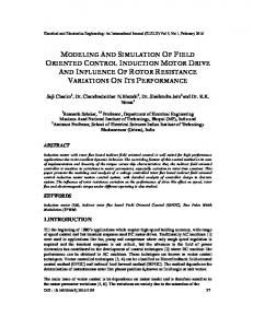
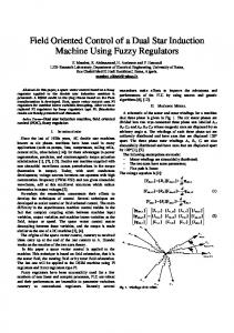
The stator phase currents are controlled in a fictitious
kept constant for fast response [8]. On the other words, the
synchronously rotating reference frame (aligned with the flux
other component, IT varies rapidly. It may be concluded that,
vector) and are transformed back to the stator frame to feed the
IM varies with the magnetizing inductance and IT with transient
machine as shown in Fig.1.
inductance of the machine. Therefore, it provides independent control of torque and flux, which is similar to a separately exited dc motor. The magnitude and phase (vector control) of the stator currents are controlled in such a way that the flux and the torque components of current remain decoupled during dynamic and static condition [4]. In order to indicate the deference between the scalar and vector control, a typical performance for torque and speed control of the system described in reference [9] shown in table-1.
Fig-1: Stator current components in d-q Frame. Field orientation can be achieved by aligning the rotor flux
TABLE-I Control Method Required by the Application or Process Torque Control: VOLUME-2, ISSUE-7, JULY-2015
linkage vector along the d axis of the reference frame. With
Motor Scalar
Motor Vector
this arrangement, the control dynamics of the highly coupled
Control
Control
nonlinear structure of the induction motor becomes linearized and decoupled. Finally, the induction motor is controlled like
COPYRIGHT © 2015 IJREST, ALL RIGHT RESERVED
6
INTERNATIONAL JOURNAL FOR RESEARCH IN EMERGING SCIENCE AND TECHNOLOGY, VOLUME-2, ISSUE-7, JULY-2015
E-ISSN: 2349-7610
an armature controlled dc motor, with Isq analogous to the
controllers [29]. This scheme is simpler to implement than the
armature current and Isd analogous to the field excitation.
direct method of (FOC). Hence, there is an increasing popularity towards the indirect method of (FOC).
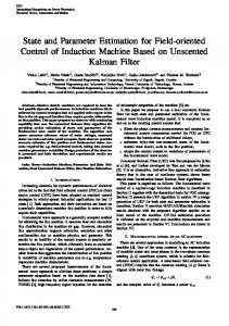
4. CLASSIFICATION OF FIELD ORIENTATION The field oriented control (FOC) system schemes can be classified into two groups: 1- Direct method of field orientation. 2- Indirect method of field orientation. Fig-3: Indirect flux sensing of induction motor vector control
4.1. Direct Field Orientation
system
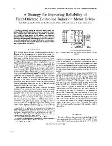
The direct method of field oriented control, which was originally proposed by BLASCHKE [10] is shown in Fig. 2. This technique utilizes direct sensing of the air gap flux vector by using one of the measurement techniques which explained briefly in section (5).
5. DETERMINATION OF FLUX VECTOR POSITION It is decisive for field oriented control (FOC) to have up-todate information [12] on the instantaneous magnitude and angular position of the flux wave
. This is the first problem
of the field orientation. The solution is discussed in the following subsections which described some of flux sensing schemes.
5.1. Air Gap Hall Sensors Hall-effect sensors are mounted in the air gap at the stator surface. There are also known as direct field sensitive devices Fig-2: Direct flux sensing of induction motor vector control system The measured air gap flux signal is feedback to the control and used to decouple the torque producing component of stator current from the producing component. Since this method uses feedback control and direct sensing of the regulated variable, it is essentially insensitive to variations.
[13]. These sensors are produce signals representing the local flux density at the measuring points. One of the (FOC) systems depending on the air gap hall sensors method is described in reference [10]. These signals are highly distorted by effect of the rotor slots and the thermal and mechanical stresses on the sensing devices [14]. Generally, the accuracy of a torque signal computed from this information is likely to be poor [15].
4.2. Indirect Field Orientation The indirect method of field oriented control, was originally proposed by HASSE [11] is shown in fig.( 1.3). This method avoids the requirement of flux acquisition (sensing devices) by using known motor parameters to compute the appropriate motor slip frequency to obtain the desired flux position [1]. On the other hands, the rotor flux is estimated from the stator current vector, voltage vector and or rotor speed, and then this estimate is, in effect, fed forward to the flux and torque VOLUME-2, ISSUE-7, JULY-2015
5.2. Sensing Coils Sensing coils having width of full pole pitch have been installed in the stator, in order to avoid the effect of rotor slots by filter out the undesirable slot harmonics [13]. This produces emf signals proportional to flux change which, after integration, taken as representing the main flux of the motor. By adding suitable components of the stator currents, signals for the rotor flux are obtained [15]. The disadvantage that,
COPYRIGHT © 2015 IJREST, ALL RIGHT RESERVED
7
INTERNATIONAL JOURNAL FOR RESEARCH IN EMERGING SCIENCE AND TECHNOLOGY, VOLUME-2, ISSUE-7, JULY-2015
E-ISSN: 2349-7610
when the drift of the integrators become too large; this would
The equivalent circuit of an induction motor is shown in Fig.
prevent the application to drives with position control such as
4, where the stator, mutual and rotor fluxes are identified.
machine tool feed drives [13]. The complete implementation of the control system depending on this method is described in work [16].
5.3. Stator Winding as Sensing Coils The last mentioned drawback is avoid by measuring the terminal voltages i.e. using the stator windings as a sensing coils. The difficulties arise from the resistance voltage drop which dominates at low frequency [12]. This disadvantage is offset by compensating the IR-drop prior to integration [15]. Since, the stator resistance is temperature dependent, the scheme in this method becomes quite difficult. Some of the field orientation control systems depending on this method are
Fig-4: Equivalent circuit of induction motor. The equations for a balanced symmetrical three-phase induction motor can be written as:
U s Rs i s d s / dt
(1)
U r Rr i r d r / dt
(2)
Te (3 / 2) Lm [is (ir e j )* ]
(3)
discussed in references [17]. Where: dθ/dt = ω, which is the rotor speed.
5.4. Machine Model: This method is remove the limitations in the low speed range, it was made possible because in the meantime microprocessors had advanced sufficiently to permit a computational solution. There are two types of machine (flux) model; voltage and current machine models. The principle of this method depends upon computing the magnetizing current Imr and the flux position φ, from the measured signals (voltage & current or current & speed) depending on the type of the model.
6. REFERENCE FRAMES FOR FIELD
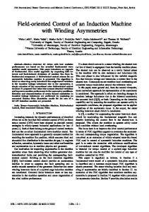
6.1. Orientation Based on Stator Flux Reference Frame The vector diagram of stator current and stator flux is shown in Fig .5, and the stator flux is given by;
s Ls i s Lm i r Lm i ms
(4)
Where
ims (1 s )i s i r
(5)
s ( Ls / Lm ) 1
(6)
ORIENTATION The control of induction motor using the principle of fieldorientation gives control characteristics similar to that of a separately exited dc motor. The torque component and the flux component of current are identified and control is exercised on them. The control variables can be decoupled by processing them appropriately, or a natural decoupling can be achieved by
Fig-5: Stator Flux and Current components
properly orienting the current vector [18]. The magnitude and
with Stator Reference Frame.
phase of the stator current determines the flux produced and the torque generated in the machine. These two parameters can
If the stator current is projected in phase and quadrature to the
be controlled by properly orienting the stator current and it can
stator flux, then:
be done with respect to one of the three specific synchronous reference frames [19]. These specific reference frames are the
is isd isq
(7)
stator flux, the air gap (mutual) flux, and the rotor flux vectors.
VOLUME-2, ISSUE-7, JULY-2015
COPYRIGHT © 2015 IJREST, ALL RIGHT RESERVED
8
INTERNATIONAL JOURNAL FOR RESEARCH IN EMERGING SCIENCE AND TECHNOLOGY, VOLUME-2, ISSUE-7, JULY-2015
E-ISSN: 2349-7610
Substituting from equations (4) to Eq. (7) in equations (1) to Eq. (3) and separating out the real and imaginary parts;
Rs isd Lm (dims / dt) U sd
(8)
Rs isq Lm1ims U sq
(9)
isd Tr (disd / dt) ( s / Ls )
(10)
s1Tr isq (Tr / Ls )[ds / dt]
s1 [isq Tr (disq / dt) /[(Tr / Ls )s
Fig-6 : Induction motor model with stator field orientation. (11)
Tr isd ]
6.2. Orientation Based on Air Gap Flux Reference
Te (3 / 2) Lm [ims isq ) (3 / 2) s .isd ]
(12)
UΦsd and UΦsq are the voltage components, ωs1 is the slip angular frequency, σ is the total leakage factor, T r is the total rotor time constant, where:
The mutual flux is defined by;
m Lm (i s i r ) Lm i m
s1 1
(13)
1 [1 /(1 s )(1 r )]
(14)
Tr Lr / Rr
Frame
Where
im i s i r
(15)
stator voltages and currents, Eq. (10) defines the build-up of flux and Eq. (12) defines the electromagnetic torque produced.
the stator voltage and currents, flux build-up, and the torque produced are given by:
imd Ts1 (dimd / dt) (U nd / Rs )
It is seen from Eq. (10), that the flux built-up not only depends
s1Ts1isq (1 / Rs )[dm / dt]
on iΦsd, but also on iΦsq and thus a coupling exists between the
imq Ts1 (dimq / dt) (U nq / Rs )
currents in the two axes. The equations (10), Eq. (11) and Eq.
s1Ts1isd (1 / Rs )m
(12) representing the structure of the induction motor in case of stator field orientation. These equations can be simplified to;
Tr isd ]
Te (3 / 2) s .isq
imd Tr1 (dimd / dt) (Tr / Lm )(dm / dt) ( m / Lm ) s1Tr1isq
s1 [imq Tr1 (disq / dt)] /[(Tr / Lm )s
(1 Tr D)isd Trs1isq
s1 (1 Tr D)isq /[(Tr / Ls )s
(20)
It can be shown in a similar way that the relationships between
Equation (8) and Eq. (9) define the relation ship between the
(1 / Ls )(1 Tr D)s
(19)
(16)
(22)
(23)
(24)
Tr1imd ]
Te (3 / 2) Lm (im imq ) (3 / 2) m .imq (17)
(21)
(25)
Where
Tr1 ( Lr Lm ) / Rr
(26)
(18) From Eq. (23), it can be inferred that the flux dynamics
Equation (16), Eq. (17) and Eq. (18) are used to construct the
depends on both the current components of stator current iΦmd
block diagram shown in Fig. 6 which describe the complexity
and iΦmq the coupling is exist. Also equation (23), Eq. (24) and
of the control with stator field orientation due to the coupling
Eq. (25) can be simplified to:
between iΦsd and iΦsq
VOLUME-2, ISSUE-7, JULY-2015
COPYRIGHT © 2015 IJREST, ALL RIGHT RESERVED
9
INTERNATIONAL JOURNAL FOR RESEARCH IN EMERGING SCIENCE AND TECHNOLOGY, VOLUME-2, ISSUE-7, JULY-2015
(1 Tr1 D)imd Tr1s1imq
(27)
(1 / Lm )(1 Tr D)m
for the flux and the torque are completely decoupled. Equ. 30 gives:
imr r / Lm
s1 (1 Tr1 D)imd /[(Tr / Lm )m
E-ISSN: 2349-7610
(38)
(28)
Tr1imd ]
Substituting from Eq. (37) in Eq. (34) and from Equ. 31 in Eq.
Te (3 / 2) m .imq
(29)
(36)
From these equations the block diagram describe the control with air gap field orientation can be constructed as shown in
ird (1 Tr D)(m / Lm )
(39)
Te (3 / 2)(Lm / Lr )(r .irq
(40)
and
Fig. 7.
Then, from Eq. (39) and Eq. (40), the model of the induction motor with rotor field orientation can be drawn in the simple block diagram shown in Fig. 8.
Fig-7: Induction Motor Model with Air Gap Field Orientation.
6.2. Orientation Based on Rotor Flux Reference Frame
Fig-8: Induction Motor Model with Rotor Field Orientation.
The rotor flux is defined by;
r Lr i r Lm i s Lm i mr
Finally, the rotor flux machine model shown in Fig. 8 contains (30)
flux through a first order time delay which is the rotor circuit
Where
i mr (1 r )i r i s
two major paths. The control input iΦrd is related to the rotor
(31)
time constant Tr. If the flux is kept constant, only the quadrature component of stator current i Φrq is used to control
And
the torque. This relationship is analogous to a separately
r ( Lr / Lm ) 1
(32)
current if the flux is held constant. Unlike the rotor flux case,
ird Ts (dird / dt) (U md / Rs ) 1Ts imq (1 )Ts [dimr / dt] irq Ts (dirq / dt) (U rq / Rs )
(33)
Fig. 6 and Fig. 7, show that the flux path is also affected by the quadrature component of stator current. This intercoupling is due to the inherent rotor leakage inductance Lr in the case of
(34)
1Ts ird (1 )Ts1imr
the air gap flux model and both the stator and rotor leakage (Ls & Lr) in the case of stator flux model [19]. Consequently, only
Tr1 (dimr / dt) i rd imr
(35)
1 irq / Tr imr
(36)
Te (3 / 2)[ Lm /(1 r )]im r irq
(37)
for the rotor flux orientation and for a constant rotor flux there is no coupling between the flux and torque in the sense that the rotor flux is produced by a constant direct component of stator current (field current) whereas the torque is produced by the
(3 / 2)[ r /(1 r )].irq
quadrature component of stator current (torque component) which is varied as desired [15]. A detail comparison between
From Eq. (35) and Eq. (37), it is evident that the flux dynamics are very simple and the stator current components responsible
VOLUME-2, ISSUE-7, JULY-2015
excited dc machine in which torque is proportional to armature
the three method of field orientation is discussed in reference [5].
COPYRIGHT © 2015 IJREST, ALL RIGHT RESERVED
10
INTERNATIONAL JOURNAL FOR RESEARCH IN EMERGING SCIENCE AND TECHNOLOGY, VOLUME-2, ISSUE-7, JULY-2015
E-ISSN: 2349-7610
7. INDUCTION MOTOR DECOUPLING CONTROL The complex nonlinear coupling structure of induction motor can be decoupled by controlling the machine with a suitable stator mmf vector. This can be done by feeding the machine with unique sets of currents and frequencies generated by decoupling control schemes [19]. The decoupling controllers are obtained by taking the inverse of the machine flux models
Fig-11: Decoupling controllers with current fed induction
shown in Fig. 6, Fig. 7 and Fig. 8. The result of this inversion
motor for stator, air gap, and rotor flux orientation
is called a decoupling network. This decoupling circuit is
These decoupling control schemes utilize an estimated slip
necessary to obtain an independent control of the flux and
angle plus the feedback rotor angle for the prediction of the
electromagnetic torque of the induction motor. Fig. 9 and Fig.
flux vector position (for the alignment of the flux vector along
10 shows the decoupling networks for rotor, stator, and air gap
the d-axis). In the stator and air gap flux decoupling control
flux orientation respectively.
schemes, a step change in command torque will case the generation of delta function due to disq/dt in Fig. 10. In practice, the rate of rise of machine currents are limited by the stator leakage inductance, therefore a very small first-order time delay is incorporated in the torque input path to ensure a smooth function of isq [19]. Then, the stator and air gap flux decoupling control schemes
Fig-9: Decoupling circuit for rotor flux orientation
shown in Fig. 10 require differentiation of isq in calculating command slip frequency. A large command slip frequency is
The decoupling circuit obtained for the indirect field oriented controller can also be used in the case of direct field orientation [20].
required during torque transient for the correct adjustment of the current vector angle φ. In order to avoid differentiation and simplify the complexity of the decoupling control scheme of Fig.11, the command slip frequency is employed instead of command torque. The modified decoupling control scheme shown in Fig. 12 utilizing command slip frequency as input. With this scheme, differentiation is eliminated and the two first order blocks can share an identical subroutine. Hence, the overall complexity is reduced.
Fig-10: Decoupling circuit for stator and air gap flux orientation The decoupling controllers based on stator, air gap, and rotor flux methods with current impressed scheme are shown in Fig. ll.
Fig-12: Modified decoupling controller scheme for stator and air gap flux orientation
VOLUME-2, ISSUE-7, JULY-2015
COPYRIGHT © 2015 IJREST, ALL RIGHT RESERVED
11
INTERNATIONAL JOURNAL FOR RESEARCH IN EMERGING SCIENCE AND TECHNOLOGY, VOLUME-2, ISSUE-7, JULY-2015
E-ISSN: 2349-7610
In case of voltage impressed schemes (voltage-fed induction
The machine parameters (Rs, Rr , Lm, and Lr) will vary due to
motor), the voltage vectors Usd and Usq can be generated from
temperature, frequency, and saturation effects. The indirect
the current and flux vector by the following relationships for
vector controller dependent on the rotor resistance Rr, the
stator, air gap and rotor flux orientation respectively:
mutual inductance Lm, and self inductance of the rotor, Lr. In particular, the rotor resistance value changes 100% with
U sdq Rs I sdq ( D js )s
(41)
temperature and frequency. This causes the actual flux and torque deviate from their set values. Also, the inductances
U sdq Rs I sdq ( D js )(Ls1 I sdq m )
(42)
U sdq Rs I sdq ( D js )(Ls I sdq
(43)
change with the saturation of magnetic material.
8.1. Parameters Sensitivitv with CSI
Lm r / Lr ) The voltage decoupling circuit (assume stator field orientation) depending on Usd* and Usq* of Eq. (41) is shown in Fig. 13. It incorporate also the current decoupling network to produce i sd* and isq* furthermore, the frequency ω1 of the flux linkage Ψ must be computed. The structure of ω1-calculator depends on the choice of control [8]. If indirect control is used, then ω 1 is calculated from ωs1* produced by the current decoupling circuit added to the rotor speed ω as shown in Fig. 13.
In the system with machine fed by impressed currents, the drive dynamics are independent of the stator supply frequency. The amount of deviation in the machine flux due to parameter variations increases with larger load values. At no-load, the variation in the ratio of actual to command flux is minimal, However, the machine torque is being adversely affected. In practice, an outer loop speed controller can be used to compensate the discrepancy in torque for particular desired speed.
8.2. Parameters Sensitivitv with VSI In the
system
with Voltage
impressed
scheme,
the
performance is speed dependent. At higher speed, the degree of sensitivity is very much lower. With voltage impression at high speeds, the machine air gap voltage is approximately equal to the terminal voltage. Therefore, variations on the rotor Fig-13: Decoupling controller with voltage-fed induction motor
resistance do not affect the machine flux model. However, at low speeds, the stator impedance voltage drop becomes significant when compared to the air gap voltage. Hence, the effect increases with varying the rotor resistance. Finally, the
8. EFFECT OF MACHINE PARAMETERS
parameter sensitivity characteristics are similar in all the three methods of flux control (stator, air gap, and rotor flux). Also it
VARIATION
similar with the current impressed scheme and the voltage
The performance of decoupling control methods based on
impressed scheme at zero speed. However, at higher speeds,
inverting machine models can be influenced by a mismatch
the latter has an edge over the former scheme [19].
between the parameters values being used in the controller and the actual machine parameters [19]. On the other hand, the parameters of the machine may change during the operation of
9. MACHINE PARAMETERS IDENTIFICATION
the drive, causing deviation between the corresponding signals of the model and the machine [21].
From the discussion of the previous section, the parameter sensitivity of the indirect vector controlled induction motor results in steady state errors in torque and flux in the addition
VOLUME-2, ISSUE-7, JULY-2015
COPYRIGHT © 2015 IJREST, ALL RIGHT RESERVED
12
INTERNATIONAL JOURNAL FOR RESEARCH IN EMERGING SCIENCE AND TECHNOLOGY, VOLUME-2, ISSUE-7, JULY-2015
of enhanced losses reducing the output of the drive system and
E-ISSN: 2349-7610
11. MICROCONTROLLER BASED FLUX
transient oscillations in flux and torque. Consequently, the
VECTOR CONTROL
efficiency of the motor drive decreases [22]. The incorporation of parameter adaptation schemes is required to off-set these
The microprocessor implementation of the field oriented
effects. These schemes are classified depending on the extent
controllers has the advantages that the hardware can be
of the use of the induction motor model. The Various schemes
simplified and as a result system reliability can be improved
which have been proposed for parameter adaptation in such
[2].
drives can be summarized based on one of the following
microprocessors is that the same standard hardware can be
strategies;
used for many different applications because the function of
The
main
advantage
of
digital
control
with
the processor determined by a flexible custom designed 1- Direct monitoring of the alignment of the flux and
software
program
[15].
Several
types
of
the
fast
microprocessors are used in the implementation of field
torque producing stator current component axes. 2- Continuous real time measurement of the instantaneous
oriented schemes such as INTEL (80386 & 80486), ZILOG 8000 or MOTOROLA 68020 to perform the machine model
rotor resistance. 3- Measurement of modified reactive power with field
and the digital controller [2]. Some of the suggested systems
angle or a combination of the rotor flux and torque
based on the microprocessors 8085 and 8086 are implemented
producing component of the stator current.
in references [12,18]. In the past, the highest performance realtime control applications have employed 8-, 16- and 32-bit
Many systems of field oriented control are implemented with
microprocessors together with interrupt handler chips,
the parameter adaptation schemes are indicated in the previous
programmable timer chips, and ROM and RAM chips, to
works such as [11,23]. A complete review on the parameters
achieve what can now be achieved in a single microcontroller
adaptation of the indirect vector controller is discussed in
chip. The microcontroller such as INTEL 8096, MOTOROLA
details in reference [24]
68HC11and SAB80C166 can be considered as microprocessor with different peripherals integrated internally with them in the
10. DIGITAL SIGNAL PROCESSING The signal processing required for the field oriented control (FOC) of ac motors as well as the flux acquisition (section 5)
same single chip, has simplified many industrial and control application. Consequently, microcontrollers are present on a commercial scale and used extensively in various industrial applications.
using a dynamic model is of considerable complexity and representing the second problem of the field orientation [15]. In the earlier implementation schemes of field oriented control systems, the analog methods had been used to perform the necessary
operations
[14].
In
particular,
the
11. SPEED ESTIMATION FOR SENSORLESS FIELD ORIENTED CONTROL SYSTEMS
various
multipliers, division and function generators needed for the
It is well known that, there are two major techniques for high
coordinate transformation are expensive and difficult to adjust
performance control of induction motor. These two techniques
when they are realized with analogue components, in view of
are, the slip frequency controlled type vector control and the
the necessary high accuracy [15]. These field oriented schemes had complicated hardware, not practical and had gained little industrial interest. The solution of this problems could be solved by converting from analog to digital techniques, using software algorithms implemented on microcomputers and signal processors [13].
field orientation control. The field oriented control system uses an electromechanical speed transducer coupled to the motor shaft to measure the rotor speed. The transducer encumbers the mechanical drive, and spoils the general characteristics of ruggedness and mechanical simplicity of the induction motor drive [25]. These speed sensors restrict the applications of vector control system, For example, if there is no space for the
VOLUME-2, ISSUE-7, JULY-2015
COPYRIGHT © 2015 IJREST, ALL RIGHT RESERVED
13
INTERNATIONAL JOURNAL FOR RESEARCH IN EMERGING SCIENCE AND TECHNOLOGY, VOLUME-2, ISSUE-7, JULY-2015
E-ISSN: 2349-7610
sensor connected, the vector control system can not be adapted
an entirely open loop basis. In the first, the angle φ of the rotor
for these system. Also, the problems for practical use, such as
flux vector is defined as follows:
a low speed behavior, have been found with speed sensors [26]. For this regard, a speed sensorless system is preferred. The advantages of sensorless induction motor drives are lower cost, reduced size of the machine set, elimination of the sensor
(48) The derivative of the above equation gives the
synchronous
speed ω1:
cable, and increased reliability. The method of vector control without any rotational transducer (sensorless) has been developed, employing the flux calculated from the stator voltages (Usα & Usβ) and the stator currents (Isα & Isβ). Since,
1 d / dt [ (d / dt) ( d / dt)] /[ ] 2
2
(49)
this method required two sensors only for measuring the stator currents and voltages. In order to obtain an accurate dynamic
Substituting for (dΨα/dt) and (dΨβ/dt) from Eq. (46) and Eq.
representation of the motor speed, it is necessary to base the
(47) in Eq. (49), then:
calculation on the coupled circuit equations of the induction motor [28]. Since, the motor voltage (Usα & Usβ) and currents
1 ( Lm / Tr )[is is ]
(Isα & Isβ) are measured in a stationary frame of reference, it is
/[ ]
also convenient to express these equations in the stationary frame (i.e. there are two different equations to estimate the rotor flux in the α-β frame).
2
2
(50)
Then, the rotor speed is given by;
1 ( Lm / Tr )[is is ]
d / dt ( Lr / Lm )U s Rs is
(44)
Ls (dis / dt)
(51)
/[ ] 2
2
Equation (51) indicate that the instantaneous rotor speed cd
d / dt ( Lr / Lm )U s Rs is
(45)
Ls ( dis / dt)
can be obtained using rotor flux estimated in Eq. (44) and Eq. (45). This process is illustrated in the block diagram shown in
and
Fig. 14.
d / dt (1 / Tr ) ( Lm / Tr )is (46) d / dt (1 / Tr ) ( Lm / Tr )is
(47)
Where: Ls, Lr : are the stator and rotor self inductances. Lm : is the mutual inductance. Rs : is the stator resistance. Tr : is the rotor time constant. ω : is the rotor electrical angular velocity. Fig-14: Block diagram for open loop calculation of rotor
σ; is the motor leakage coefficient.
speed.
Ψ, is, Us, : are the rotor flux, stator current, and stator voltage
This open loop calculation process requires knowledge of four
respectively
constants that depends on the motor parameters. The Equation (44) and Eq. (45) does not contain the rotor speed ω.
parameter sensitivity can be reduced by calculating the slip in
However, Eq. (46) and Eq. (47) does. Thus, by using these two
rotating reference frame (d-q frame) that is locked to the rotor
equations, the instantaneous rotor speed ω can be calculated
flux vector. There are two problems for this speed estimation
directly from the measuring values of voltages and currents on
technique related to the rotor flux estimation in Eq. (44) and
tan ( / )
1 VOLUME-2, ISSUE-7,JULY-2015
COPYRIGHT © 2015 IJREST, ALL RIGHT RESERVED
14
INTERNATIONAL JOURNAL FOR RESEARCH IN EMERGING SCIENCE AND TECHNOLOGY, VOLUME-2, ISSUE-7, JULY-2015
Eq. (45). The first problem is the need of an ideal integral
[7]
E-ISSN: 2349-7610
I. Takahashi & T. Noguchi "A New Quick Response and
where the calculated rotor flux does not work so that it is
High Efficiency Control Strategy of an Induction
unstable in initial operation, as motor speed approaches zero.
Motor", Proc. lEEE/IA Ann. Conf. Rec., pp. 496-502,
The second problem is the dependence of motor parameters,
1985.
such as stator resistance thermal variation and saturation of
[8]
inductance parameters. Particularly, stator resistance variation causes the calculated rotor flux to vary and lead to torque
Ion Boldea, & Syed A. Nasar "Vector Control of AC Drive", CRC press, Florida 1992.
[9]
variation in a low speed range.
G. O. Garcia, R. M. Stephan, & E. H. Watanabe "Comparing the Indirect Field-Oriented Control with a Scalar Method", IEEE Trans. Ind. Elec., Vol. 41, No. 2
12. CONCLUSIONS
[10]
F. Blaschke "The Principle of Field Orientation as
This paper reviews the various aspects in the field oriented
Applied to the New Transvector Oosed Loop Control
control
System for Rotating Field Machine", Siemens Rev., Vol.
of
induction
motor
including
the
principles,
37, No. 5, pp. 217-220, June 1972.
classification (direct and indirect FOC), and the flux vector position determination. The mathematical models of the stator
[11]
K. Hasse "Zur Dynamik Drehzahlgeregegelter Antriebe
flux, the air gap flux, and the rotor flux reference frames was
mit
determined. The decoupling control with current and voltage
Kurzschlusslaufermachinen" ("On the dynamics of speed
fed induction motor for stator, air gap, and rotor flux
control of static ac drives with squirrel-cage induction
orientation was discussed. The field oriented control makes the
machines"), Ph.D. dissertation, TH Darmstadt, 1969.
induction motor is controlled like an armature controlled dc
[12]
stomrich-tergespeisten
Asynchron-
R. Gabriel & W. Leonhard "Microprocessor Control of
motor, with Isq analogous to the armature current and Isd
Induction Motor", IEEE Ind. Appl., Society Annual
analogous to the field excitation. It is expected that the review
Meeting, pp. 385-395, 1982.
will help those interested in the field of efficient and high
[13]
W. Leonhard "30 Years Space Vectors, 20 Years Field Orientation, 10 Years Digital Signal Processing with
performance drives.
Controlled AC Drives, a Review", EPE Journal, Vol. 1, No. 2, pp. 89-102, October 1991.
REFERENCES [1]
M. H. Rashid "Power Electronics Circuits, Devices, and
[14]
Doncker "Universal Field Oriented Controller Based on
Applications", Englewood Cliffs, New Jersey, 1988. [2]
Air Gap Flux Sensing via Third Harmonic Stator
B. K. Bose "Introduction to AC Drives, Speed Control of
Voltage", IEEE Trans., Ind. Appl., Vol. 30, No. 2, pp.
AC Drives", IEEE Collection, pp. 1-21, 1978. [3]
448-455, March/April 1994.
S. B. Dewan, G. R. Slemon, & A. Stranghen "Power Semiconductor Drives", Published in Canada, 1984.
[4]
[15]
[16]
Ind. Appl., Vol. IA-13, No. 2, pp. 139-146, March/April
A. K. Ibrahim "Performance Characteristics of Induction Drives
Under
Field
Oriented
1977.
Control
Techniques", M.Sc. Thesis, Faculty of Engineering,
[17]
using Tapped Stator Windings", IEEE Trans. Power
S.Yamamura & T. Nakagawa "Equivalent Circuit and
Elec., Vol. 5, No. 4, pp. 446-453, October 1990,
Field Acceleration Method of AC Servomotor by Means of Induction Motor", Trans. lEE Japan, Vol. 102-B, No. 7, pp. 433- 439, 1985.
VOLUME-2, ISSUE-7, JULY-2015
D. S. Zinger, T. A. Lipo, & D. W. Novotny "A Direct Field Oriented Controller for Induction Motor Drives
Cairo University, 1994. [6]
A. B. Plunkett "Direct Flux and Torque Regulation in a PWM Inverter- Induction Motor Drive", IEEE Trans.,
No. 6, pp. 562-575, December 1990.
Motor
W. Leonhard "Control of Electrical Drives", SprigerVerlag, New York, 1985.
P. C. Sen "Electric Motor Drives and Control-Past, Present, and Future", IEEE Trans. Ind. Eiec., Vol. 37,
[5]
G. B. Griva, M. Pastroelh, J. C. Moreira, & R. W. DE
[18]
S. Sathiakumar, S. K. Biswas, & J. Vithayathil "Microprocessor Based Field-Oriented Control of a CSI-
COPYRIGHT © 2015 IJREST, ALL RIGHT RESERVED
15
INTERNATIONAL JOURNAL FOR RESEARCH IN EMERGING SCIENCE AND TECHNOLOGY, VOLUME-2, ISSUE-7, JULY-2015
[19]
E-ISSN: 2349-7610
Fed Induction Motor Drive", IEEE Trans., Ind. Elec.,
Induction Motor Drives", IEEE Trans. Ind. Appl., Vol.
Vol. IB-33, No. 1, pp. 39-43, February 1986.
IA-21, No. 4, pp. 624-632, May/June 1985.
Edward Y. Y. Ho & P. C. Sen "Decoupling Control of Induction Motor Drives", IEEE Trans., Ind. Elec., Vol. 35, No. 2, pp. 253-262, May 1988.
[20]
R. W. DE Doncker & D. W. Novotny "The Universal Field Oriented Controller", IEEE Trans., Ind. Appl., Vol. 30, No. 1, pp. 92-100, Jan/February 1994.
[21]
J. Holtz & T. Thimm "Identification of the Machine Parameters in a Vector-Controlled Induction Motor Drive", IEEE Trans., Ind. Appl., Vol. 27, No. 6, pp. 1111-1118, November /December 1991,
[22]
J. Holtz "Speed Estimation and Sensorless Control of AC Drives", lECON' 93, International Conference on Ind, Elec. Control and Instrumentation, Vol. 2, pp. 649-654, Hawaii, USA, 1993.
[23]
F. M. H. Khater, R. D. Lorenz, D. W. Novotny, & K. Tang "Selection of Flux Level in Field Oriented Induction Machine Controllers wit Consideration of Magnetic
Saturation
Effects",
IEEE
Trans.,
Ind.
Appl.,Vol. IA-23, No. 2, pp. 276-281, March/April 1987. [24]
R. Krishnan & A. S. Bharadwaj "A Review of Parameter Sensitivity and Adaptation in Indirect Vector Controlled Induction Motor Drive Systems", IEEE Trans., Power Elec., Vol. 6, No. 4, pp. 695-703, October 1991.
[25]
L. Ben-Brahim & A. Kawamura "A Fully Digitized Field-Oriented Controlled Induction Motor Drive using Only Current Sensors", IEEE Trans., Ind. Elec., Vol. 39, No. 3, pp. 241-249, June 1992.
[26]
T. Ohtani, N. Takada, & K. Tanaka "Vector Control of Induction Motor Without Shaft Encoder", IEEE Trans., Ind. Appl., Vol. 28, No. 1, pp. 157-164, Jan/February 1992.
[27]
C. Schauder "Adaptive Speed Identification for Vector Control of Induction Motors Without Rotational Transducers", IEEE Trans., Ind. Appl, Vol. 28, No. 5, pp. 1054-1061 Sept/October 1992.
[28]
C. Schauder "Adaptive Speed Identification for Vector Control of Induction Motors Without Rotational Transducers", IEEE Trans., Ind. Appl, Vol. 28, No. 5, pp. 1054-1061 Sept/October 1992.
[29]
Takayoshi Matsuo & Thomas A. Lipo "A Rotor Parameter Identification Scheme for Vector ControUed
VOLUME-2, ISSUE-7, JULY-2015
COPYRIGHT © 2015 IJREST, ALL RIGHT RESERVED
16