Load Balancing for QoS Optimisation in Wireless LANs Utilising Advanced. Cell Breathing ... Cork Institute of Technology, Cork, Ireland. E-Mail: {obrickley, srea, ...
Load Balancing for QoS Optimisation in Wireless LANs Utilising Advanced Cell Breathing Techniques Olivia Brickley, Susan Rea, Dirk Pesch Centre for Adaptive Wireless Systems Department of Electronic Engineering Cork Institute of Technology, Cork, Ireland E-Mail: {obrickley, srea, dpesch}@cit.ie Abstract— Wireless Local Area Networks (WLANs) have become increasingly popular over the last number of years. During this time, user requirements have evolved, resulting in a more diverse mix of services being carried over the wireless medium. In particular, delay sensitive real-time applications such as streaming multimedia and voice over IP are growing in importance. The widely accepted IEEE 802.11b standard, however, was not designed with sufficient Quality of Service (QoS) constraints for such applications. This paper will attempt to optimise the received quality in 802.11b WLAN by balancing the load between various access points while changing the coverage area of each access point, a technique commonly known as cell breathing.
I. INTRODUCTION In recent years wireless local area networks (WLANs) have become increasingly popular and today are commonly found in town centres, campuses and corporate buildings. They have begun to replace their wired equivalent and thus, are expected to support the same applications that are being provided over the wired medium. Such network applications include streaming multimedia, voice and web browsing, all of which have different requirements with regards to bandwidth, delays, jitter and packet loss. These quality of service (QoS) parameters are not currently taken into consideration in IEEE’s widely deployed 802.11b standard [1]. IEEE’s 802.11b details MAC and PHYsical layer specifications for WLAN operating at the 2.4GHz frequency band. It is widely adopted, relatively inexpensive and almost readily available everywhere. It can provide up the 11Mbps and has a range of 100 to 150 feet indoors. The standard defines two medium access mechanisms: the Point Coordination Function (PCF) and the Distributed Coordination Function (DCF). The PCF is an optional mode that was designed with real-time services such as voice or video in mind. It is a centrally controlled access mechanism that allows for contention free access to the wireless medium. Stations are polled periodically and given the opportunity to transmit. The PCF, however, has not been widely deployed in today’s WLANs and as a result, isn’t considered in this paper. The DCF access mechanism is a mandatory best effort service that was originally designed for data services such as e-mail, web browsing and ftp. However, in recent times, as WLANs have become more popular, the type of service being provided over the network
0-7803-8887-9/05/$20.00 (c)2005 IEEE
has evolved to include real-time applications such a voice and video streaming. These multimedia applications have strict delay requirements, which cannot be explicitly guaranteed by the DCF. Under heavy load conditions at an access point (AP), large delays may be experienced at the MAC layer, which could cause a serious degradation in QoS for video or voice applications. Balancing the load on the network among a number of AP’s would reduce delays and collisions and hence improve the QoS perceived by users. The load in a WLAN is rarely evenly divided among all access points. Most mobile nodes may be associated with one access point while neighbouring access points could be lightly loaded or idle. Terminals associated with the overloaded AP will experience high rates of collision and large delays when contending for medium access. By redistributing some of the mobile nodes to neighbouring AP’s, the load on the network becomes more evenly distributed, allowing an increase in overall network throughput and a decrease in MAC delay. Load balancing can be a useful means of improving the network performance during congestion periods. This paper is structured as follows. Section II discusses the IEEE802.11b standard. Section III describes the cell breathing scheme developed to balance the load on an AP in an effort to improve the QoS received by users. Section IV describes the simulation environment used to test the proposed scheme, while Section V demonstrates and accounts for the results gathered. Section VI details future work to be carried out in the area of cell breathing for WLAN and finally, the conclusions of this study are presented in Section VII. II. IEEE 802.11B DCF The DCF is the basic access mechanism of IEEE 802.11b. It employs a Carrier Sense Multiple Access with Collision Avoidance (CSMA/CA) mechanism to control access to the wireless medium. CSMA/CA is similar to the medium access scheme used in the IEEE 802.3 Ethernet standard. Both mechanisms use a “listen before talk” technique where nodes must sense that the medium is idle before transmitting. In the DCF, a node wishing to transmit a frame must first win contention to the medium. This procedure involves
DIFS
DIFS
Defer Access
Source
Contention Window
Medium Busy
Backoff Window Slot Time
Next Frame
Decrement backoff as long as the medium is idle
DIFS RTS
Destination
Data
SIFS
SIFS CTS
SIFS ACK
Other NAV (RTS)
Figure 1. The DCF medium access procedure Medium is busy. Defer Access
carrier sensing and is illustrated in Figure 1. The node must sense the wireless channel to be idle for a DIFS (Distributed InterFrame Space) period before it can attempt to transmit. If the medium is determined to be busy, the terminal waits until the end of the current transmission before initiating a backoff procedure. During backoff, the station randomly selects a backoff counter value. This determines how many timeslots the station will back off for before again attempting to transmit on the channel. The counter is decremented by one for every timeslot in which the channel is sensed idle. If the channel becomes busy during the backoff process, the counter is paused until the channel is sensed idle again for a DIFS. When the backoff counter reaches zero, the node begins its transmission. Each terminal maintains a Contention Window (CW) parameter. The backoff counter is randomly chosen from the range [0,CW]. The CW defines the range of values from which the backoff counter can be chosen. The CW is set at a minimum value for each new frame to be transmitted. As the number of retries increases, so too does the CW. Therefore, backoff times become greater as the number of retransmissions increase decreasing the likelihood of the colliding terminals choosing the same backoff time. While stations connected to an Ethernet can detect collisions that have occurred on the medium, WLAN nodes cannot. Instead, 802.11b terminals try to avoid collisions by using virtual sensing. Each station has a Network Allocation Vector (NAV) which predicts how long the medium will be busy. Nodes will only try to contend for the right to transmit if their NAV is zero. Each frame contains a duration field that defines the period of time that the medium is to be reserved to transmit a data frame and its associated ACK. Any nodes that overhear a frame will update their NAV based on the value contained in the duration field. The presence of the duration field in frames decreases the likelihood of collisions occurring since all nodes will overhear at least one of the frames in the sequence and will consequently update their NAV accordingly. When a node wins contention it begins its transmission using a RTS/CTS frame exchange. The source node sends a short frame called a Request To Send (RTS) to the intended recipient of the data. On receiving a RTS frame a terminal will generate a Clear To Send (CTS) and after a Short InterFrame Space (SIFS) sends it back to the source. Once a CTS has successfully been received, the originating node waits for a SIFS period and sends the data frame. When the
Figure 2. The DCF frame exchange sequence.
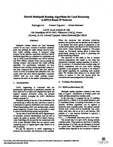
destination station receives the data frame, an acknowledgement frame (ACK) is transmitted after a SIFS. This simple frame exchange sequence is shown in Figure 2. If a collision occurs and one of the frames is not received correctly, then the originating terminal backs off for a randomly chosen period and starts the contention process for retransmission of the data frame. If the number of retransmissions reaches the predefined limit, the frame is discarded [1]. In DCF, all traffic types have equal access rights to the wireless medium. In a heavily loaded WLAN cell, there is a much higher probability of multiple terminals attempting to transmit at one time. This means that the low latency necessary for real-time services cannot be guaranteed. A scheme that could reduce the load at the affected access point would have a significant effect on the throughput and delays experienced by users. III. LOAD BALANCING USING CELL BREATHING Users are rarely evenly distributed over the entire network. Load balancing schemes provide an element of congestion relief to those AP’s with a high density of users. Neighbouring AP’s that are lightly loaded agree to accept stations with the aim of improving or maintaining overall network performance as well as the QoS provided to end users. Much literature exists on the subject of load balancing for WLAN [2, 3, 4]. The authors in [2] have implemented a scheme in which access points aim to fairly distribute bandwidth among all users. The mobile terminals will choose to associate with the AP that can best provide its bandwidth request. Algorithms for adaptive load balancing are presented in [3]. Here, the network attempts to handle user service requests by readjusting the load across all AP’s. If an AP cannot accommodate the new session request, the network suggests a location in the network where the request can be satisfied. In [4], three possible AP states: under-loaded, balanced and overloaded, are defined. The throughput per AP is used as a load metric in deciding the AP state. The node uses this information when choosing an AP to associate with. Under heavy loading conditions in DCF mode, the rate of collisions and hence the number of retransmissions escalates. This causes a serious/notable decrease in network
throughput and hence reduced QoS because bandwidth is consumed for frame retransmissions. Overloading at an AP also has an effect on the delays experienced at the MAC layer. A high number of collisions results in a high number of retransmission attempts and hence, longer backoff periods. Should the delay at the MAC layer become too large, real-time applications such as video and voice will experience high frame dropping rates. This will result in a serious deterioration of the QoS being experienced by these delay-sensitive applications. This paper proposes to use the concept of cell breathing in a cellular WLAN environment to balance the load between access points (AP’s) and hence improve the overall QoS in the network. Cell breathing is a technique where by an AP can reconfigure its cell boundaries by changing the power at which it transmits. Reducing the transmit power will have the effect of shrinking coverage area of the AP. On the other hand, if the transmit power is increased then the cell size is effectively enlarged. This cell breathing technique, if applied to WLAN, can give the network the ability to adapt itself to changing load conditions. Specifically, decreasing the transmission range of an AP reduces the load in that basic service set area (BSS). Reducing the number of active users in the BSS area will cause a decrease in the number of collisions taking place on the wireless medium. This, in turn, lessens the amount of bandwidth consumed for retransmissions and results in an overall increase in network throughput. If the load becomes too high in one BSS and QoS degrades to an intolerable level, then the AP attempts to shed users by reducing it’s transmit power, causing a decrease in the cell size. Figure 3 illustrates this cell breathing technique. The load at BSS 1 increases to the point that the AP becomes overloaded with traffic. With so many stations contending for access to the wireless medium, the rate of collisions will be high and bandwidth will be consumed for retransmission of frames. To combat this, AP1 reduces its transmission power resulting in a smaller coverage area and hence looses users that must be absorbed by its neighbours. IV. SIMULATION ENVIRONMENT The proposed cell breathing scheme is evaluated by means of a computer simulation model of the 802.11b standard using the communications network class library (CNCL) [10]. The service mix will consist of voice and video traffic mainly because these are envisaged to be the most common real-time services provided over WLANs. These are two different classes of service each with its own QoS requirements. This allows a comparison of how each type of network user is affected when the network is overloaded. The video is streamed over the network at a rate of 256Kbps using a H263 video model. A 32Kbps voice service is also implemented using the two-state on-off model developed by Brady [11]. The simulation scenario in use can be seen in Figure 4. This model is the single floor plan of Block B in Cork Institute of
New BSS boundary Previous BSS boundary Mobile Station AP 1
AP 2
BSS 1
Figure 3. Cell Breathing Procedure. BSS 1 becomes smaller and to compensate for this, AP 2 increases it’s transmit power to make sure all stations receive coverage
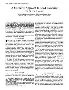
Figure 4. The WLAN environment used in simulation and analysis of QoS for 802.11.
Technology. The plan is colour-coded to illustrate the received signal strength values at each point in the area. Six access points are positioned on this floor in Block B and can be identified by areas of red colour. Details, such as the thickness and composition of all obstacles between receiver and transmitter are taken into consideration for pathloss calculations. The pathloss model employed for this work is the Motif Model [8]. Nodes move within the environment using a mobility model similar to the City Section model as described in [9]. A number of predefined points are located throughout the area. Each mobile node begins the simulation at one of these defined sites. A node then randomly chooses an end point as its destination. Information on the adjacency of sites is used in determining the shortest path from source to destination. All mobile nodes move towards the end site at a random speed between .05 and 5 metres per second. Upon reaching its destination, the node will dwell there for a random pause time before choosing its next destination. V. RESULTS The objective of the cell breathing process is to improve the QoS received by users in the WLAN. Voice and video applications in particular are considered in this paper because both have strict QoS requirements. The main parameter used to quantify the performance of these
The introduction of cell breathing has a notable affect on the overall network performance. Figure 8 shows that using the load balancing scheme greatly reduces the number of frames dropped during the simulation. This is most notable in the video traffic which has seen up to a 50% reduction in the number of frames being dropped as more sessions are added. Figure 9 illustrates the drop in the number of collisions using the cell breathing scheme. When the number of collisions increases dramatically, the cell breathing scheme is enforced due to the deterioration in the QoS. We can see from the graph, that when the load balancing scheme is run, the number of collisions is greatly reduced. This is particularly apparent in the voice service. Finally, Figure 9 shows the effect of cell breathing on the average overall network throughput. As can be seen there is a notable increase in the average throughput in the network after the cell breathing scheme has been applied. This is most apparent in the video service, where we see a
No. dropped frames
2000 Video
1500
Voice
1000
500
0 10
20
30
40
50
No. Active Sessions
Figure 5. The number of frames dropped without cell breathing 300
250
No. of collisions
Figures 5, 6 and 7 illustrate network performance without the proposed load balancing scheme. It can be seen from Figure 5 that the numbers of frames dropped increases dramatically as more sessions are introduced into the network. As seen in Figure 6, the number of collisions is also affected by the load increase. The voice application has a much higher collision rate than video because it is transmitted on both the uplink and downlink. The video is streamed from a server and routed to its destination through the access point. This means that all video traffic is on the downlink making the probability of collision small. Figure 7 shows the average network throughput for the duration of the simulation. For video, the throughput reaches a high of 117Kbps but once the number of active sessions exceeds 20, it experiences a steady decline. Voice reaches a throughput of 12Kbps, a value which also decreases as the load on the network gets larger.
2500
200 Video
150
Voice
100
50
0 10
20
30
40
50
No. of active sessions
Figure 6. The number of collisions occurring without cell breathing 140000 120000 verage Throughput (bps)
Simulations begin with 100 nodes randomly positioned over the coverage area. Each node scans the environment and based on the received signal strength from each AP performs the association procedure. After a settling down period of 30 seconds, users start requesting services. Ten new sessions are launched every 20 seconds for 120 seconds. This is done in an effort to ensure the network is highly loaded so the true performance of the cell breathing scheme can be tested.
3000
100000 80000
Video Voice
60000 40000 20000 0 10
20
30
40
50
No. of Active Sessions
Figure 7. The average overall network throughput per active session., without cell breathing. 1200
1000
Dropped Frames
services is the frame drop rate. For voice and video, frames that have experienced large delays at the MAC layer become stale and are dropped. Video frames become stale when their successor enters the queue, while video frames can sustain up to 200ms delay before being dropped. The video streaming application can tolerate a frame drop rate of up to 5%. Anything above this value is deemed bad QoS. The voice service can tolerate up to 2% frame dropping while still delivering acceptable quality.
800 Video
600
Voice
400
200
0 10
20
30
40
50
No of active Sessions
Figure 8. Number of dropped frames when cell breathing is implemented.
involve the use of Fuzzy Logic for decision-making. A fuzzy controller will decide under what conditions cell breathing should be executed.
200 180 160
Collisions
140 120 Video
100
Voice
80 60 40 20 0 10
20
30
40
50
No of active sessions
Figure 9. The number of collisions with the cell breathing scheme
180 160
Throughput Kbps
140
VII. CONCLUSION This paper presents a cell breathing concept in cellular WLAN that performs load balancing with the aim of improving the QoS for real-time applications. Access points can dynamically adjust their transmission power in an attempt to shed users to reduce the cell load. Neighbouring AP’s also make power adjustments to try and ensure that all nodes continue to receive coverage. The handover procedure from one AP to another is seamless. This load balancing technique allows the network to adapt itself to changing network load conditions in order to maintain or improve the current level of service being provided to users. Results show that the proposed scheme does indeed improve the level of service received by users in the form of lower frame dropping rates and improved overall throughput. Work is already underway on implementing this scheme in 802.11e to determine if its performance can also be improved using cell breathing.
120 100
Video Voice
80 60 40 20 0 10
20
30
40
50
No of avtive sessions
Figure 10. The average overall network throughput with cell breathing
maximum improvement of almost 50% when there are 30 active sessions. VI. FUTURE WORK The widely accepted IEEE 802.11b standard was not designed with sufficient Quality of Service (QoS) constraints for real-time applications. A new draft part of the standard, named 802.11e, has been proposed that deals with QoS issues for Wireless LANs. This enhanced access mechanism does provide an improved QoS for timebounded services. The higher priority traffic receives the highest throughput and lower access delay at the MAC layer. However, this improved QoS is provided at the cost of a reduced performance for lower priority traffic. As the load on the network increases, the lower priority traffic, for example, web or ftp traffic becomes starved of access to the wireless medium [5], [6], [7]. Future work will aim to perform the cell breathing technique outlined in this paper in a WLAN network running the 802.11e standard. This should negate or at least lessen the possibility that the lower priority traffic becomes starved during heavy network load conditions. Other work will
REFERENCES [1]
"Part 11: Wireless Medium Access Control (MAC) and Physical Layer (PHY) Specification", ANSI/IEEE Std 802.11, 1999 Edition [2] Y. Bejerano, S. Han, L.i Li, "Fairness and Load Balancing in Wireless LANs Using Association Control", Proc. ACM MobiCom, Philadelphia, PA, USA, Sept 2004 [3] A. Balachandran, P. Bahl, G. Voelker, "Hot-Spot Congestion Relief in Public-Area Wireless Networks" [4] H Velayos, V. Aleo, G. Karlsson, "Load Balancing in Overlapping Wireless LAN Cells", Proc. IEEE ICC, Paris, France, June 2004 [5] D. Grilo and M. Nunes. "Performance evaluation of IEEE 802.11E", Proc IEEE PIMRC, pp. 511–517, 2002. [6] D.He, C.Q.Shen, "Simulation Study if IEEE 802.11e EDCF", Proc. IEEE VTC-Spring 2003, Jeju, Korea, May 2003 [7] S. Mangold et al, "IEEE 802.11e Wireless LAN for Quality of Service", Proc. European Wireless, Florence, Italy, Feb 2002 [8] M. Klepal, "Novel Approach to Indoor Electromagnetic Wave Propagation Modelling", Doctoral Thesis, Czech Technical University, Prague, Czech Republic, 2003 [9] T. Camp, J Boleng and V. Davies, "ASurvey of Mobility Models for Ad Hoc Network Research", Proc. IEEE WCNC, Orlando, FL, USA, March 2002 [10] M. Junius, M. Steppler, M. Buter, D. Pesch, "Communications Networks Class Library", Edition 1.12, September 1999 [11] P.T. Brady "A Model for on-off speech patterns in two-way conversation", Bell Syst. Tech J, September 1969