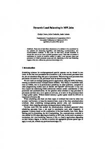
Table 1: 802.11e Traffic Priority to AC mapping. Figure 1: Each AC has its own transmit queue and contends for the channel independently of other the ACs. AC0.
Load Balancing for QoS Enhancement in IEEE802.11e WLANs Using Cell Breathing Techniques Olivia Brickley, Susan Rea, Dirk Pesch Centre for Adaptive Wireless Systems Department of Electronic Engineering Cork Institute of Technology, Cork, Ireland E-Mail: {obrickley, srea, dpesch}@cit.ie Abstract— Wireless Local Area Networks (WLANs) have become increasingly popular over the last number of years. During this time, user requirements have evolved, resulting in a more diverse mix of services being carried over the radio interface. In particular, delay sensitive real-time applications such as streaming multimedia and voice over wireless IP are growing in importance. The widely accepted IEEE 802.11b standard however, was not designed with such Quality of Service (QoS) constraints in mind. A new draft of the standard named 802.11e has been specified that deals with QoS issues for Wireless LANs. This work looks at this enhancement and will attempt to improve the quality that a user will receive by balancing the load between various access points while changing the coverage area of each access point, a technique commonly known as cell breathing. Keywords: WLAN, Load Balancing, QoS, 802.11, Cell Breathing
I. INTRODUCTION In recent years wireless local area networks (WLANs) have become increasingly popular and today are commonly found in town centres, campuses and corporate buildings. They have begun to replace their wired equivalent and thus, are expected to support the same applications that are being provided over the wired medium. Such network applications include streaming multimedia, voice and web browsing, all of which have different requirements with regards to bandwidth, delay, jitter and packet loss. These quality of service (QoS) parameters are not currently taken into consideration in IEEE’s widely deployed 802.11b/g standard [1]. IEEE’s 802.11b details MAC and PHYsical layer specifications for WLAN operating at the 2.4GHz frequency band. It is widely adopted, relatively inexpensive and almost readily available everywhere. It can provide up to 11Mbps and has a range of 100 to 150 feet indoors. The standard defines two medium access mechanisms: the Distributed Coordination Function (DCF) and the Point Co-ordination Function (PCF). The DCF access mechanism is a mandatory best effort service that was originally designed for data services such as e-mail, web browsing and ftp. However, in recent times, as WLANs have become more popular, the type of service being provided over the network has evolved to include real-time applications such a voice and video streaming. These multimedia applications have strict delay requirements, which cannot be explicitly guaranteed by the DCF. The PCF is an optional mode that was designed with real-time services such as voice or video in mind. It is a centrally controlled access mechanism that allows for contention free access to the wireless medium. Stations are polled periodically and given the opportunity to transmit. The PCF, however, has not been widely deployed in today’s WLANs. It can provide only limited QoS because of
unpredictable time delays in beacon transmission and polling causes a decrease in throughput as the number of nodes increases [1]. As a result, the 802.11 task group E was formed and work is currently underway on 802.11e, an enhancement of the existing standard that takes into consideration QoS requirements. 802.11e specifies the hybrid co-ordination function which employs prioritized medium access. Higher priority traffic is permitted to use shorter inter-frame space and backoff times. This means that traffic with strict QoS requirements spends less time contending for access to the wireless medium, experiencing little delay as a result. This enhancement to 802.11b has been shown to provide an improved QoS for time-bounded services [6, 7, 8]. However, under heavy load conditions at an access point (AP), large delays may be experienced at the MAC layer, causing a serious degradation in QoS for video or voice applications. Balancing the load on the network among a number of APs would reduce delays and collisions and hence improve the QoS perceived by users. The load in a WLAN is rarely evenly divided among all access points. Most mobile nodes may be associated with one access point while neighbouring access points could be lightly loaded or idle. Terminals associated with the overloaded AP will experience high rates of collision and large delays when contending for medium access. By redistributing some of the mobile nodes to neighbouring APs, the load on the network becomes more evenly distributed, allowing an increase in overall network throughput and a decrease in MAC delay. Load balancing can be a useful means of improving the network performance during congestion periods. This paper is structured as follows. Related work in the area of load balancing for WLAN is presented in the next section.
Section III discusses the IEEE802.11e enhancement for QoS in WLAN. Section IV describes the cell breathing scheme developed to balance the load on an AP in an effort to improve the QoS received by users. Section V describes the simulation environment used to test the proposed scheme, while Section VI demonstrates and accounts for the results gathered. Finally, the conclusions of this study are presented in Section VII. II. RELATED WORK As users are rarely evenly distributed over the entire network, the introduction of load balancing schemes provides an element of congestion relief to those APs with a high density of users. Neighbouring APs that are lightly loaded agree to accept stations with the aim of improving or maintaining overall network performance as well as the QoS provided to end users. Some literature exists on the subject of load balancing for WLAN [3, 4, 5]. The authors in [3] have implemented a scheme in which access points aim to fairly distribute bandwidth among all users. Here, mobile terminals will choose to associate with the AP that can best provide its bandwidth request. Algorithms for adaptive load balancing are presented in [4]. Here, the network attempts to handle user service requests by readjusting the load across all APs. If an AP cannot accommodate the new session request, the network suggests a location in the network where the request can be satisfied. This work requires the user to physically move location to another BSS area if its request cannot be granted at its current position in what is described as network-directed roaming. In [5], three possible AP states: under-loaded, balanced and overloaded, are defined. The throughput per AP is used as a load metric in deciding the AP state. The node uses this information when choosing an AP to associate with. This work uses the throughput per AP as the load metric. While this metric gives an accurate indication of how busy an AP is, it does not take into consideration the QoS being provided to the ongoing sessions at that AP. In this paper we propose a dynamic load balancing scheme that takes into consideration the QoS being received by users.
AC’s at the station. This is illustrated in figure 1. In EDCA, differentiated channel access is realised by varying the size of the contention window and the time spent sensing the channel. In 802.11b’s DCF, nodes must sense the channel to be idle for a DIFS period before attempting to transmit. In 802.11e, the DIFS is replaced by the arbitrary inter-frame space (AIFS). The highest priority AC has the smallest AIFS while the lowest priority traffic has the largest AIFS. This means that higher priority traffic has a better chance of accessing the channel more quickly. The size of the contention window also varies for each AC. The contention window size determines for how long a node will back off before attempting to gain access to the channel. The contention window size starts at CWmin and is doubled for each retransmission of the frame until the maximum window size, CWmax, is reached. Higher priority AC’s have smaller CWmin and CWmax values for selecting the backoff duration. Thus, higher priority traffic backs off for shorter periods resulting in faster access to the channel. Figure 2 illustrates EDCA timing for AC’s x, y and z, where x > y > z. Based on the EDCA system described above, AIFS[x] < AIFS [y] < AIFS[z], CWmin[x] < CWmin[y] < CWmin[z] and CWmax[x] < CWmax[y] < CWmax[z]. In the diagram, AC[x] represents the highest priority AC and therefore has the shortest AIFS, and the smallest backoff window. It is these parameters that help ensure AC[x] gets access to the medium ahead of lower priority AC’s y and z. Priority
Access Category
Traffic Type
0
0
Best Effort
1
0
Best Effort
2
0
Best Effort
3
1
Video Probe
4
2
Video
5
2
Video
6
3
Voice
7
3
Voice
Table 1: 802.11e Traffic Priority to AC mapping
III. IEEE 802.11E AC0
AC1
AC2
AC3
Contention AC 2
Contention AC 3
802.11e is an enhancement to the already existing 802.11b MAC. It specifies the hybrid coordination function (HCF) that performs both contention-based and contention-free access to the medium. Contention-free access is carried out by an improved version of the DCF called the enhanced distributed channel access (EDCA). Contention AC0
The EDCA performs service differentiation by means of prioritised medium access. This QoS support is provided with the introduction of access categories (AC’s). Each station has four AC’s that can have one or more user priorities assigned to it. AC’s are seen as virtual stations, each with its own transmission queue and priority parameters [2]. Each AC performs contention and backoff independently from other
Contention AC 1
Internal Collision Management Transmission on channel
Figure 1: Each AC has its own transmit queue and contends for the channel independently of other the ACs
New BSS boundary
AIFS[z] Next Frame AIFS[y] AIFS[x]/ AIFS[y]/ AIFS[z] AIFS[x]
Contention Window 0 to Cmin[x]
Medium Busy
Defer Access
Previous BSS boundary
Next Frame
Backoff Window Slot Time
Mobile Station AP 1
AP 2
Next Frame
Decrement backoff as long as the medium is idle
Figure 2: EDCA timing. Each AC acts as an independent MAC function and has its own AIFS and CWmin values.
In a heavily loaded WLAN cell, there is a much higher probability of multiple terminals attempting to transmit at one time. This means that even with prioritised access high priority traffic could experience large delays due to collisions. A scheme that could reduce the load at the affected access point would have a significant effect on the QoS being provided to the user. IV. LOAD BALANCING USING CELL BREATHING Under heavy load conditions, the rate of collisions and hence the number of retransmissions escalates. This causes a serious or at least notable decrease in network throughput and hence reduced QoS because more and more bandwidth is consumed for frame retransmissions. Overloading at an AP also has an effect on the delays experienced at the MAC layer. A high number of collisions results in a high number of retransmission attempts and hence, longer backoff periods. Should the delay at the MAC layer become too large, realtime applications such as video and voice will experience high frame dropping rates. This will result in a serious deterioration of the QoS being experienced by these delaysensitive applications. This paper proposes to use the concept of cell breathing in a cellular WLAN environment to balance the load between access points (APs) and hence improve the overall QoS in the network. Cell breathing is a technique whereby an AP can reconfigure its cell boundaries by changing the power at which it transmits. Reducing the transmit power will have the effect of shrinking coverage area of the AP. On the other hand, if the transmit power is increased then the cell size is effectively enlarged. This cell breathing technique, if applied to WLAN, gives the network the ability to adapt itself to changing load conditions. Specifically, decreasing the transmission range of an AP reduces the load in that basic service set area (BSS). Reducing the number of active users in the BSS area will cause a decrease in the number of collisions taking place on the wireless medium. This, in turn, lessens the amount of bandwidth consumed for retransmissions and results in an overall increase in network throughput.
BSS 1
Figure 3: Cell Breathing Procedure. BSS 1 becomes smaller and to compensate for this, AP 2 increases it’s transmit power to make sure all stations receive coverage
If the load becomes too high in one BSS and QoS degrades to an intolerable level, then the AP attempts to shed users by reducing it’s transmit power, causing a decrease in the cell size. Figure 3 illustrates this cell breathing technique. The load at BSS 1 increases to the point that the AP becomes overloaded with traffic. With so many stations contending for access to the wireless medium, the rate of collisions will be high and bandwidth will be consumed for retransmission of frames. To combat this, AP1 reduces its transmission power resulting in a smaller coverage area and hence looses users that must be absorbed by its neighbours. Each AP transmits at a power Ptx = in dBm, where in ∈{0, 7, 13, 15, 17, 20} and n = (1…6). in represents the 6 power levels at which APs transmit. APs also monitor DRvideo and DRvoice,. These values represent the overall frame drop rate for video and voice sessions that the AP is supporting. Both traffic types have a threshold on the amount of frame dropping that can occur, DropThresholdvideo and DropThresholdvoice. Figure 4 portrays the workings of the proposed cell breathing scheme. When a frame drop occurs, the current DR values are calculated. If the AP determines that it is overloaded, i.e. if its DR > DropThreshold for either service type, the cell breathing procedure is initiated. The overloaded AP notifies neighbouring APs of its desire to reduce Ptx. Neighbours respond to these notification frames by increasing their own Ptx. This is done to ensure that no station is left without coverage. Frame Drop
Calculate DRvoice and DRvideo
if(DRvoice > DropThresholdvoice || DRvideoe > DropThresholdvideo ) Notify neighbour APs about overloading
Reduce transmit power to Ptx = in-1
Figure 4: Cell Breathing Algorithm
V. SIMULATION ENVIRONMENT The proposed cell breathing scheme is evaluated by means of a computer simulation model of the 802.11e protocol implemented based on the communications network class library (CNCL) [11]. The service mix will consist of voice and video traffic mainly because these are envisaged to be the most common real-time services provided over WLANs. These are two different classes of service each with its own QoS requirements. This allows a comparison of how each type of network user is affected when the network is overloaded. The video is streamed over the network at a rate of 256Kbps using a H263 video model [13]. A 32Kbps voice service is also implemented using the two-state on-off model developed by Brady [12]. In accordance with 802.11e specification, voice calls have the highest priority and use access category 3. Video sessions belong to access category 2. Table 2 below outlines the MAC parameters for these traffic types as specified in [2]. MAC Parameters
Voice
Video
AIFS
50
50
CWmin
7
15
CWmax
15
31
defined sites. A node then randomly chooses an end point as its destination. Information on the adjacency of sites is used in determining the shortest path from source to destination. All mobile nodes move towards the end site at a random speed between .05 and 5 metres per second. Upon reaching its destination, the node will dwell there for a random pause time before choosing its next destination. VI. RESULTS The objective of the cell breathing process is to improve the QoS received by users in the WLAN when the network is heavily loaded. Voice and video applications in particular are considered in this paper because both have strict QoS requirements. The main parameter used to quantify the performance of these services is the frame drop rate. For voice and video, frames that have experienced large delays at the MAC layer become stale and are dropped. Video frames become stale when their successor enters the queue, while voice frames can sustain up to 200ms delay before being dropped. The video streaming application can tolerate a frame drop rate, DropThresholdvideo, of up to 5%. Anything above this value is deemed bad QoS. The voice service can tolerate up to 2% frame dropping, DropThresholdvoice, while still delivering acceptable quality.
Table 2: MAC Parameters used in system simulation
120 nodes are randomly positioned throughout the coverage area for each simulation run. Each node scans the environment and based on the received signal strength from each AP performs the association procedure. After a settling down period of 30 seconds, users start requesting services. Five new video sessions and five voice calls are launched every 10 seconds for 120 seconds. This is done in an effort to ensure the network is highly loaded so the true performance of the cell breathing scheme can be tested.
Figure 5. The WLAN environment used in simulation and analysis of QoS for 802.11.
The simulation scenario in use can be seen in Figure 5. This model is the single floor plan of Block B in Cork Institute of Technology. The plan is colour-coded to illustrate the received signal strength values at each point in the area. Six access points are positioned on this floor in Block B and can be identified by areas of red colour. Details, such as the thickness and composition of all obstacles between receiver and transmitter are taken into consideration for pathloss calculations. The pathloss model employed for this work is the Motif Model [9]. Nodes move within the environment using a mobility model similar to the City Section model as described in [10]. A number of predefined points are located throughout the area. Each mobile node begins the simulation at one of these
Figures 6 and 7 illustrate network performance without the proposed load balancing scheme. It can be seen from Figure 6 that the load in the network is very unevenly distributed with APs 3 and 6 carrying the majority of the network traffic. As a direct result of this, the rate of frame dropping in those BSS areas is quite high and at times well over the threshold values. This is evident in figure 7, where we can see that the FDR for both APs almost reaches 40%, a highly unacceptable figure. The figure also highlights the absence and insignificance of frame dropping at lightly loaded neighbouring access points; APs 4 experiences a brief period of frame dropping but this never exceeds the QoS threshold. Figure 8 demonstrates the AP loading states after using the proposed cell breathing scheme. This figure demonstrates the greedy nature of the proposed algorithm. AP6 performs cell breathing causing an overspill of stations into an already highly loaded BSS3. AP3, in turn, initiates cell breathing, transferring some of the load back to AP6. The latter half of the graph illustrates the load balancing nature of cell
breathing with all access points are fairly evenly distributed towards the end of the simulation. This is a major contrast to the scenario in figure 6, where the load on the network was highly imbalanced. This balancing of the load in the network also has an effect on the overall frame dropping rate, DR. Figure 9 clearly validates this. The peak drop rate in this scenario is under 15%, compared to almost 40% without load balancing.
Drop %
Dropping Rate
Assoc. Nodes
AP Loading
AP2 AP3 AP4 AP5 AP6
30
50
70
90
110
130
150
170
Time (secs)
AP1 AP2
Figure 9: The rate of frame dropping in each BSS area using cell breathing
AP3 AP4 AP5 AP6 9 20 31 44 58 70 81 94 107 121133 147159 173184 Time (sec)
Figure 6: AP loading without cell breathing Dropping Rate
Drop %
AP1
10
100 90 80 70 60 50 40 30 20 10 0 1
0.45 0.4 0.35 0.3 0.25 0.2 0.15 0.1 0.05 0
AP1 AP2 AP3 AP4
improving the QoS. Access points can dynamically adjust their transmission power in an attempt to shed users to reduce the cell load. Neighbouring APs also make power adjustments to try and ensure that all nodes continue to receive coverage. The handover procedure from one AP to another is seamless. This load balancing technique allows the network to adapt itself to changing network load conditions in order to maintain or improve the current level of service being provided to users. Results show that the proposed scheme does indeed improve the level of service received by users in the form of lower frame dropping rates and improved overall throughput. Work is also underway on an extension to this algorithm in which overloaded APs consider the loading situation at neighbouring APs before adjusting transmit power.
AP5 AP6 10
30
50
70
90
110
130
150
[2]
Figure 7: The average frame dropping occurring in each BSS area without cell breathing AP Loading 100 90 80 70 60 50 40 30 20 10 0
REFERENCES [1]
170
Time (secs)
Assoc. Nodes
0.45 0.4 0.35 0.3 0.25 0.2 0.15 0.1 0.05 0
[3]
[4] [5] AP1 AP2 AP3
[6] [7]
AP4 AP5
[8]
AP6
[9] 1
12 26 42 61 72 81 93 108 125 140 153 166 178 Time (secs)
Figure 8: The load at each AP using the cell breathing scheme
VII. CONCLUSION This paper presents a cell breathing concept in cellular WLAN that performs load balancing with the aim of
[10]
[11] [12] [13]
"Part 11: Wireless Medium Access Control (MAC) and Physical Layer (PHY) Specification", ANSI/IEEE Std 802.11, 1999 Edition "Amendment 7: Medium Access Control (MAC) Quality of Service (QoS) Enhancements" IEEE P802.11e, October 2004 Y. Bejerano, S. Han, L.i Li, "Fairness and Load Balancing in Wireless LANs Using Association Control", Proc. ACM MobiCom, Philadelphia, PA, USA, Sept 2004 A. Balachandran, P. Bahl, G. Voelker, "Hot-Spot Congestion Relief in Public-Area Wireless Networks" WMCSA, June 2002 H Velayos, V. Aleo, G. Karlsson, "Load Balancing in Overlapping Wireless LAN Cells", Proc. IEEE ICC, Paris, France, June 2004 D. Grilo and M. Nunes. "Performance evaluation of IEEE 802.11E", Proc IEEE PIMRC, pp. 511–517, 2002. D.He, C.Q.Shen, "Simulation Study if IEEE 802.11e EDCF", Proc. IEEE VTC-Spring 2003, Jeju, Korea, May 2003 S. Mangold et al, "IEEE 802.11e Wireless LAN for Quality of Service", Proc. European Wireless, Florence, Italy, Feb 2002 M. Klepal, "Novel Approach to Indoor Electromagnetic Wave Propagation Modelling", Doctoral Thesis, Czech Technical University, Prague, Czech Republic, 2003 T. Camp, J Boleng and V. Davies, "A Survey of Mobility Models for Ad Hoc Network Research", Proc. IEEE WCNC, Orlando, FL, USA, March 2002 M. Junius, M. Steppler, M. Buter, D. Pesch, "Communications Networks Class Library", Edition 1.12, September 1999 P.T. Brady "A Model for on-off speech patterns in two-way conversation", Bell Syst. Tech J, September 1969 K. Rijkse "H.263: Video Coding for Low-Bit-Rate Communications", IEEE Communications Magazine, December 1996