load and resistance factors in the Ontario Highway Bridge. Design Code ...... Mechanics Division, University of Waterloo, Waterloo, Ont. Study No. 2, p. 124. Can.
Load model for bridge design code ANDRZEJ S. NOWAK Departnletlt of Civil and E ~ ~ v i r o r ~ n ~ eEngineering, r~tal University of Michigan, At111 A r b o ~ MI , 48109-2125, U.S.A.
Can. J. Civ. Eng. Downloaded from www.nrcresearchpress.com by 216.208.156.69 on 06/05/13 For personal use only.
Received January 8, 1993 Revised manuscript accepted May 26, 1993 The paper deals with the development of load model for the Ontario Highway Bridge Design Code. Three components of dead load are considered: weight of factory-made elements, weight of cast-in-place concrete, and bituminous surface (asphalt). The live load model is based on the truck survey data. The maximum live load moments and shears are calculated for one-lane and two-lane bridges. For spans up to about 40 m, one truck per lane governs; for longer spans, two trucks following behind the other provide the largest live load effect. For two lanes, two fully correlated trucks govern. The dynamic load is modeled on the basis of simulations. The results of calculations indicate that dynamic load depends not only on the span but also on road surface roughness and vehicle dynamics. Load combination including dead load, live load, dynamic load, wind, and earthquake is modeled using Turkstra's rule. The maximum effect is determined as a sum of the extreme value of one load component plus the average values of other simultaneous load components. The developed load models can be used in the calculation of load and resistance factors for the design and evaluation code. Key words: bridge, dead load, live load, dynamic load, load combinations. Cet article traite du dCveloppement d'un modble de charge pour le Code de conception des ponts routiers de I'Ontario (CCPRO). Trois caractkristiques de la charge permanente ont CtC CtudiCes : le poids des ClCments fabriquCs a I'usine, le poids du bCton coulC sur place ainsi que celui du revstement bitumineux (asphalte). Le modble de charge mobile a CtC ClaborC en tenant compte de certaines mesures et de donnCes d'enquste sur les camions. Les moments et les cisaillements maximums dus h la surcharge ont CtC calculCs pour des ponts a une et deux voies. Pour les portCes d'une longueur de 40 m et moins, l'effet maximal est causC par un camion par voie; pour les portCes plus longues, deux camions qui se suivent crCent l'effet le plus important en termes de charge mobile. La modClisation de la charge dynamique a CtC effectuie en tenant compte de simulations. Les rCsultats des calculs indiquent que la charge dynamique depend non seulement de la portCe, mais aussi de la rugositC de la surface de roulement et de la dynamique des vChicules. Une combinaison de charges comprenant la charge permanente, la charge mobile, la charge dynamique, le vent et les secousses sismiques a fait I'objet d'une modClisation l'aide de la rbgle de Turkstra. L'effet maximal est obtenu en additionnant la valeur extrgme d'une caractkristique de charge et les valeurs moyennes des autres. Les modbles de charge ClaborCs peuvent servir au calcul des coefficients de rksistance et de charge pour le code de conception et dlCvaluation. Mots cle's : pont, charge permanente, charge mobile, charge dynamique, combinaisons de charge. [Traduit par la rCdaction] Can. I. Civ. Eng. 21. 3 6 4 9 (1994)
Introduction Bridge loads play an increasingly important role in the development of design and evaluation criteria. The fundamental load combination includes dead load, live load, and dynamic load. This paper deals with the derivation of statistical model for these load components. T h e presented research provided statistical models for the development of load and resistance factors in the Ontario Highway Bridge Design Code (OHBDC) 1991 edition. he analysis of bridge loads was performed in conjunction with the development of two previous editions of the OHBDC (Nowak and Lind 1979; Grouni and Nowak 1984). Load models were developed on the basis of the available truck surveys and other measurements. T h e maximum 50-year live load was determined by exponential extrapolation of the extreme values obtained in the survey. AASHTO (1989) girder distribution factors were used in the analysis. Dynamic load was modeled using the available test data. The new developments affect dead load, live load, and dynamic load. Dead load is based on the latest available data. The live load model is developed for one-lane and NOTE:Written discussion of this paper is welcomed and will be received by the Editor until June 30, 1994 (address inside front cover). Printed in Canada / Innprime nu C:ln;~d;l
two-lane bridges. An important part of this study is the dynamic load analysis. The model is developed on the basis of an analytical simulation of the actual bridge behavior. The major load components of highway bridges are dead load, live load, (static and dynamic), environmental loads (temperature, wind, earthquake), and other loads (collision, emergency braking). The load models are developed using the available statistical data, surveys, and other observations. Load components are treated as random variables. Their variation is described by the cumulative distribution function, the mean value, and the coefficient of variation. The relationship between load parameters is described by a coefficient of correlation. T h e basic load combination for highway bridges is a simultaneous occurrence of dead load, live load, and dynamic load. T h e combinations involving other load components (wind, earthquake, collision forces) require a special approach which takes into account a reduced probability of a simultaneous occurrence of extreme values of several independent loads.
Dead load Dead load, D, is the gravity load due to the self weight of the structural and nonstructural elements permanently connected to the bridge. Because of different degrees of varia-
NOWAK
TABLE1. Statistical parameters of dead load Component
Mean-to-nominal
Factory-made members Cast-in-place members Asphalt Miscellaneous
1.03 1.05 90 mm* 1.03- 1.05
Coefficient of vibration
Can. J. Civ. Eng. Downloaded from www.nrcresearchpress.com by 216.208.156.69 on 06/05/13 For personal use only.
"Mean thickness.
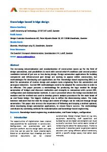
tion, it is convenient to consider the following components of D: ( i ) D , , the weight of factory-made elements (steel, precast concrete members); (ii) Dz, the weight of cast-inplace concrete members; (iii) D,, the weight of the wearing surface (asphalt); and (iv) D,, miscellaneous weight (e.g., railing, luminaries). All components of D are treated as normal random variables. T h e statistical parameters used in the calibration are listed in Table 1. T h e bias factors (mean-to-nominal ratios) are taken as in the previous calibration work (Nowak and Lind 1979). However, the coefficients of variation are increased to include human errors, as recommended by Ellingwood et al. (1980). The thickness of asphalt was first modeled on the basis of statistical data available from the Ontario Ministry of Transportation (MTO). Measurements were done in various regions of the Province. The distributions of D, (thickness of asphalt) are plotted on normal probability paper in Fig. 1. The average thickness of asphalt is 75 mm. The coefficient of variation, calculated from the slope of the distributions in Fig. 1, is 0.25. However, further information provided by the MTO indicates that the mean thickness of asphalt has increased to 90 mm and the coefficient of variation is reduced to 0.15 (Agarwal, yet unpublished). For miscellaneous items (weight or railings, curbs, luminaries, signs, conduits, pipes, cables, etc.), the statistical parameters (means and coefficients of variation) are similar to those of D,, if the considered item is factory-made with the high quality control measures, and D2, if the item is cast-in-place, with less strict quality control.
Live load data base Live load, L, covers a range of forces produced by vehicles moving on the bridge. Traditionally, the static and dynamic effects are considered separately. Therefore, in this study, L covers only the static component. The dynamic component is denoted by I. T h e effect of live load depends o n many parameters, including the span length, truck weight, axle loads, axle configuration, position of the vehicle on the bridge (transverse and longitudinal), number of vehicles on the bridge (multiple presence), girder spacing, and stiffness of structural members (slab and girders). The live load model is based on the truck survey in Ontario performed by the MTO in 1975. The study covered about 10 000 selected trucks (only trucks that appeared t o be heavily loaded were measured and included in the data base). The results of the 1988 truck survey including over 2000 trucks (Agarwal, yet unpublished) are also considered to study the changes in live load over the years. T h e uncertainties involved in the analysis are d u e t o limitations and biases in the survey data. Even though 10 000 trucks is a large number, it is very small compared with the actual number of heavy vehicles in a 50-year life-
Actual Asphalt Thickness / 75 mm
FIG. 1. Cumulative distribution functions of asphalt thickness by MTO re,'oions. time. It is also reasonable to expect that some extremely heavy trucks purposefully avoided the weighing stations. A considerable degree of uncertainty is caused by unpredictability of the future trends with regard to the configuration of axles and weights. The 1975 Ontario survey included a total of 9250 heavy trucks (Agarwal and Wolkowicz 1976). For each truck, bending moments and shear forces were calculated for a wide range of simple spans. The cumulative distribution functions are plotted on normal probability paper in Fig. 2 for moments and Fig. 3 for shears, for spans from 9 to 60 m. The construction and use of the normal probability paper is explained in the fundamental textbooks o n probability theory (eg., Benjamin and Cornell 1970). The horizontal scale is in terms of the OHBDC (1983) live load (truck or lane load, whichever governs), as shown in Fig. 4. The vertical scale, z, is [l] z = a-'[F,(x)] where F,(x) is the cumulative distribution function of X, X
Can. J. Civ. Eng. Downloaded from www.nrcresearchpress.com by 216.208.156.69 on 06/05/13 For personal use only.
38
CAN. J . CIV. ENG. VOL. 21. 1991
Moment / OHBDC-1983Moment FIG. 2. Cumulative distribution functions of truck moments from 1975 survey in terms of the OHBDC-1983 moment.
OHBD Truck
Shear / OHBDC-1983Shear FIG. 3. Cumulative distribution functions of truck shears from 1975 survey in terms of the OHBDC-1983 shear.
200 kN
160 kN
i40m i40m 60 kN
OHBD Lane Load
I
I
I
I
FIG. 4. OHBDC-1983
being the moment or the shear; and a-' is the inverse of the standard normal distribution function. The moments and shears were also calculated for the 1988 truck survey data. T h e resulting cumulative distribution
live load.
functions of moments and shears are plotted in Fig. 5 and Fig. 6, respectively. T h e results do not indicate any considerable change in the maximum moments and shears in the two surveys.
Can. J. Civ. Eng. Downloaded from www.nrcresearchpress.com by 216.208.156.69 on 06/05/13 For personal use only.
-4
-4
0
0.5
1
0
1.5
Moment / OHBDC-1983 Moment FIG.5. Cumulative distribution functions of truck moments from 1988 survey in terms of the OHBDC-1983 moment.
Maximum truck moments and shears The maximum moments and shears for various time ~ e r i o d s are determined by extrapolation of the distributions as shown in Figs. 7 and 8. Let N be the total number of trucks in time period T. It is assumed that the surveyed trucks represent about 2-week traffic on a class A highway. Therefore, in T = 50 years, the number of trucks, N, will be about 1000 times larger than in the survey. This will result in N = 10 million trucks. The probability level corresponding to N is 1/N; for N = 10 million, the probability is 1/10 000 000 = lo-', which corresponds to z = 5.19 on the vertical scale, as shown in Figs. 7 and 8. The number of trucks (N), the probability (l/N), and the inverse normal distribution value (z) corresponding to various time periods (T), from 1 day to 75 years, are shown in Table 2. The lines corresponding to the con. 8. sidered probability levels are also shoin in ~ i ~7 sand The mean maximum moments and shears corresponding to various periods of time can be read directly from the graph. For example, for 15 m span and T = 5 0 years, the mean maximum moment is 1.2 times the design moment. It is equal to the horizontal coordinate of intersection of the extrapolated distribution and z = 5.19 on the vertical scale. For comparison, the number of trucks passing through the bridge in 75 years is 1500 times larger than in the survey. This corresponds to z = 5.26 on the vertical scale (Figs. 7 and 8). Similar calculations can be performed for other periods of time. The mean moments and shears calculated for time periods from 1 day to 7 5 years are presented in Figs. 9 and 10,
0.5
1
1.5
Shear / OHBDC-1983 Shear FIG.6. Cumulative distribution functions of truck shears from 1988 survey in terms of the OHBDC-1983 shear.
75 Years 50 Years 5 Years 1Year
6 Months 2 Months 1Month 2weeks 1 Day
-4
0
0.5
1
1.5
Moment / OHBDC1983 Moment
FIG.7. Extrapolated cumulative distribution functions of truck moments.
40
C A N . I. CIV. ENG. VOL. 21, 1994
TABLE2. Number of trucks vs. time period and probability 75 Years 50 Years 5 Years 1 Year
Can. J. Civ. Eng. Downloaded from www.nrcresearchpress.com by 216.208.156.69 on 06/05/13 For personal use only.
6 Months 2 Months 1 Month 2 Weeks 1 Day
Time period T
Number of trucks
Probability
Inverse normal
N
1IN
7
75 years 50 years 5 years 1 year 6 months 2 months 1 month 2 weeks 1 day TABLE 3. Bias factors - ratio of the maximum 50-year live load and OHBDC-1983 design live load (per lane) Single truck Span (m)
0.0
0.5 1.O Shear / OHBDG1983 Shear
Moment
Shear
One or two trucks Moment
Shear
1.5
FIG. 8. Extrapolated cumulative distribution functions of truck shears. respectively. For comparison, the means are also plotted for an average truck. The coefficients of variation for the maximum truck moments and shears can be calculated by transformation of the distribution functions in Figs. 7 and 8. Each function can be raised to a certain power, so that the calculated earlier mean maximum moment (or shear) becomes the mean value after the transformation. The slope of the transformed cumulative distribution function determines the coefficient of variation. The results are plotted in Figs. 11 and 12 for moments and shears, respectively. For 50 years, the bias factors are also given in Table 3.
One-lane moments and shears For one-lane bridges, the maximum effect (moment or shear) is caused by a single truck or two (or more) trucks following behind each other. For a multiple truck occurrence, the important parameters are the headway distance and the degree of correlation between truck weights. The maximum one-lane effect is derived as the largest of the following cases: (a) Single truck effect equal to the maximum 50-year moment (or shear) with the parameters (mean and coefficient of variation) given in Figs. 9 and 11 for the moment and in Figs. 10 and 12 for the shear; (b) Two trucks, each with the weight smaller than that of a single truck in case (a). Three degrees of correlation between truck weights are considered: none (p = 0), partial (p = 0.5), and full (p = l ) , where p is the coefficient of correlation. It is assumed that, on average, about every 50th truck is followed by another truck with the headway distance less than 30 m, about every 250th truck is followed by a partially correlated truck, and about every 500th truck is fol-
lowed by a fully correlated truck. The two trucks are denoted by T I and T,. Three cases are considered: ( i ) No correlation between T I and T? The parameters of T, are taken for every 50th truck, or the maximum of 200 000 (1-year truck in Table 2). This corresponds to z = 4.42 on the vertical scale in Figs 7 and 8. T h e parameters of T, are taken for an average truck. (ii) Partial correlation between T I and T7. The parameters of T I are taken for every 250th truck, or the maximum of 40 000 (2-month truck in Table 2). This corresponds to z = 4.05 on the vertical scale in Figs. 7 and 8. The parameters of TZ are taken for every 1000th truck, or the maximum of 1 0 0 0 ( I - d a y truck in Table 2 ) , which c o r r e s p o n d s t o z = 3.09. (iii) Full correlation between T I and Tz. The parameters of T I and T, are taken for every 500th truck, or the maximum of 20 000 (I-month truck in Table 2), which corresponds to z = 3.89 on the vertical scale in Figs. 7 and 8. The truck effects are determined by simulation for various time periods, for a headway distance equal to 5 m (bumperto-bumper traffic). The results are presented in Figs. 13 and 14. For the 50-year period, the bias factors are also listed in Table 3. A comparison with Figs. 9 and 10 indicates that one truck governs for spans less than 30-40 m. For longer spans, two fully correlated trucks govern. The headway distance of 5 m is associated with non-moving vehicles or
NOWAK
75 Years 50 Years 5 Years 1 Year 6 Months 2 Months 1 Month 2 Weeks 1 Day
Can. J. Civ. Eng. Downloaded from www.nrcresearchpress.com by 216.208.156.69 on 06/05/13 For personal use only.
Average Truck
Span (m)
FIG.9. Bias factors for various time periods: moment for a single truck.
75 Years 50 Years 5 Years 1 Year 6 Months 2 Months 1 Month 2 Weeks 1 Day
Average Truck
Span (m)
FIG. 10. Bias factors for various time periods: shear for a single truck. trucks moving at reduced speeds. This is important in consideration of dynamic loads. In further calculations, it is assumed, conservatively, that the headway distance is 5 m even for normal speeds.
Two-lane moments and shears The analysis involves the determination of the load in each lane and the load distribution to girders. The effect of multiple trucks is calculated by superposition. The maximum moments are calculated as the largest of the following cases: (a) One lane fully loaded and the other lane unloaded; (b) Both lanes loaded. Three degrees of correlation between the lane loads are considered: no correlation (p = 0), partial correlation (p = 0.5), and full correlation (p = 1). It has been observed that, on average, about every 10th truck is on the bridge simultaneously with another truck
(side-by-side). For each such a simultaneous occurrence, it is assumed that every 10th time the trucks are partially correlated and every 50th time they are fully correlated (with regard to weight). It is also conservatively assumed that the transverse distance between two side-by-side trucks is 1.2 m (wheel center-to-center). In case (a) (only one lane loaded), the parameters (mean and coefficient of variation) of the maximum effects are as given in Table 3. In case (b) (two lanes loaded), the parameters of moments and shears in each lane depend on the degree of correlation: (i) No correlation (p = 0). The maximum 50-year moment is caused by a simultaneous occurrence of the maximum 5-year moment (2 = 4.75) in lane 1 and the average moment in lane 2. (ii) Partial correlation (p = 0.5). The maximum 50-year moment is caused by a simultaneous occurrence of the max-
42
CAN. J. CIV. ENG. VOL. 21. 1994
Can. J. Civ. Eng. Downloaded from www.nrcresearchpress.com by 216.208.156.69 on 06/05/13 For personal use only.
Average Truck
1 Day 2 Days 2 Weeks 1 Month 2 Months 6 Months 1 Year 5 Years 50 & 75 Years
Span (m) FIG. 11. Coefficient of variation of the maximum moment for a single truck. Average Truck
1 Day 2 Days 2 Weeks 1 Month 2 Months 6 Months 1 Year 5 Years 50 & 7 5 Years
span (m) FIG. 12. Coefficient of variation of the maximum shear for a single truck. imum 6-month moment (z = 4.26) in lane 1 and the maximum daily moment (z = 3.09) in lane 2. (iii) Full correlation (p = 0). T h e maximum 50-year moment is caused by a simultaneous occurrence of the maximum 1-month moment (z = 3.89) in both lanes. The structural analysis was performed using the finite element method. The model is based on a linear behavior of girders and slabs. The maximum girder moments and shears were calculated by superposition of truck loads in both lanes. The results indicate that for interior girders, the case with two fully correlated side-by-side trucks governs, with each truck equal to the maximum 1-month truck. However, for some cases of exterior girders, one truck may govern. The bias factors are calculated as the ratios of the mean maximum 50-year moments (shears) and nominal moments (shears) specified by OHBDC ( 1983). The calculations are
performed for a single lane and two lanes. The results are plotted vs. span in Figs. 15 and 16. For two lanes, the multilane reduction factor (0.9) is included.
Recommended changes in design live load On the basis of the performed load analysis, it is recommended to increase the design load for spans less than 40 m. Therefore, the tandem axle load has been increased from the current OHBDC (1983) 140 kN to 160 kN (see Fig. 4). The bias factors, calculated using the new live load (160 kN per axle in a tandem), are shown in Figs. 17 and 18 for moments and shears, respectively. Dynamic load Dynamic load effect, I, is considered as an equivalent static load effect added to the live load, L. The objective
NOWAK
8
4
1.3
1.2
h
M
s 90
1.1
7 5 Years 50 Years 5 Years 1 Year 6 Months 2 Months 1 Month 2 Weeks 1 Day
V
1.0
E0 \
11
5
Can. J. Civ. Eng. Downloaded from www.nrcresearchpress.com by 216.208.156.69 on 06/05/13 For personal use only.
$ 6 - 0
1'g @
.2
0.9 0.8
0.7
a
0.6 0
10
20
30
40
50
60
Span (m)
FIG. 13. Bias factors for various time periods: moment for one-lane bridges.
7 5 Years 50 Years 5 Years 1 Year 6 Months 2 Months 1 Month 2 Weeks 1 Day
Span (m) FIG. 14. Bias factors for various time periods: shears for one-lane bridges
of this analysis is to determine the parameters (mean and coefficient of variation) of I. The dynamic bridge tests were carried out by Billing (1984). The results are available for 22 bridges and 30 spans, including prestressed concrete girders and slabs, steel girders (hot-rolled sections, plate girders, box girders), steel trusses, and rigid frames. The measurements were taken for test vehicles and a normal traffic. The means and standard deviations, as a fraction of the static live load, are given in Table 4. Considerable differences between the distribution functions for very similar structures point to the importance of other factors (e.g., surface condition). Results collected from the weigh-in-motion studies (Ghosn and Moses 1984) indicate an average dynamic load factor of 0.11. This value falls in the middle range of the data obtained from the MTO tests (Table 4). However, interpretation of these results is difficult because the dynamic loads are separated from the static live loads. It has been observed that the dynamic load, as a fraction of live load, decreases for heavier trucks. It
is expected that the largest dynamic load fractions in the survey correspond to light-weight trucks. To verify these observations, a computer procedure was developed for simulation of the dynamic bridge behavior (Hwang and Nowak 1991). The dynamic load is a function of three major parameters: road surface roughness, bridge dynamics (frequency of vibration), and vehicle dynamics (suspension system). The developed model includes the effect of these three parameters. Simulation of the dynamic load requires the generation of a road profile, which is done by using a Fourier transform of the power spectral density function. The bridge is modeled as a prismatic beam. Modal equations of motion are formulated. In the analysis, each truck is composed of a body, a suspension system, and tires. The body is subjected to a rigid-body motion including the vertical displacement and pitching rotation. Suspensions are assumed to be of multi-leaf type springs. The dynamic load allowance (DLA) is defined as the maximum dynamic deflection, D,,,,divided by the maximum
Can. J. Civ. Eng. Downloaded from www.nrcresearchpress.com by 216.208.156.69 on 06/05/13 For personal use only.
CAN. 1. CIV. ENG. VOL. 21, 1994
Span (m) FIG. 15. Bias factors for various time periods: moments for one-lane bridges in terms of OHBDC-1983 model.
Span (m) FIG. 16. Bias factors for various time periods: shears for one-lane bridges in terms of OHBDC-1983 model. static deflection, D,,,, as shown in Fig. 19. Static and dynamic deflections are calculated for typical girder bridges. It has been observed that the absolute value of the dynamic deflection is almost a constant. Therefore, as the gross vehicle weight is increased, the dynamic load allowance is decreased. The decrease of DLA is mainly due to the increase of static deflection. In most cases, the maximum live load is governed by two trucks side-by-side. The corresponding DLAs are calculated for two trucks by superposition of one truck effects as shown in Fig. 20. The obtained average DLAs for one truck and two trucks are presented in Fig. 21. Therefore, the resulting mean dynamic load is 0.10 of the mean live load for two trucks and 0.15 for one truck. The coefficient of variation is 0.80.
In OHBDC (1983), the design values of DLA are specified as a function of the natural frequency of vibration, as shown in Fig. 22. T h e results of simulations indicate that DLA values can be reduced and they are lower for two trucks than for one truck. In general, dynamic load is reduced for a larger number of axles. Furthermore, DLA is applied to the maximum 50-year live load. The actual DLA is close to the mean. Therefore, it is recommended to use a DLA equal to 0.25 for spans larger than 6 m.
Load combinations T h e total load, Q, is a combination of several components. The following combinations are considered in this paper:
NOWAK
-
two lanes
Can. J. Civ. Eng. Downloaded from www.nrcresearchpress.com by 216.208.156.69 on 06/05/13 For personal use only.
\ FIG. 17. Bias factors for moments for one-lane and two-lane bridges in terms of OHBDC-1991 model.
FIG. 18. Bias factors for shears for one-lane and two-lane bridges in terms of OHBDC-1991 model. (1) D (2)D (3) D
+ L + I; + L + I + W; + L + I + EQ;
where W is the wind load and EQ is the earthquake load. The maximum 50-year combination of live load, L, and dynamic load, I , is modeled using the statistical parameters derived for L and I. It is assumed that live load is a product of two parameters, L and P, where L is the static live load and P is the live load analysis factor (influence factor). The mean value of P is 1.0 and the coefficient of variation is 0.12. The coefficient of variation of LP can be calculated using the following formula: [2]
v,,
= (v;
+ vp2)'I2
where V, is the coefficient of variation of L and V, is the coefficient of variation of P. The mean maximum 50-year LP I , nz,,,,, can be calculated by multiplying the mean L by the mean value of P (equal to 1.0) a n d by (1 m,), w h e r e m, is the mean dynamic load. T h e standard deviation of the maximum 50-year LP + I , u,,+,, is
+
+
in,, is the mean LP and is equal to where a,, = V,,m,,; mean L , because mean P = 1; and a, = V,m, is the standard deviation of the dynamic load. The coefficient of variation of LP + I , V,,,,, is
CAN. J. CIV. ENG. VOL. 21, 1994
TABLE4. Dynamic load factors from test results Mean
Standard deviation
Type of structure
Range
Average
Range
Average
Prestressed concrete AASHTO girders Prestressed concrete box and slabs Steel girders Rigid frame, truss
0.05-0.10 0.10-0.15 0.08-0.20 0.10-0.25
0.09 0.14 0.14 0.17
0.03-0.07 0.08-0.40 0.05-0.20 0.12-0.30
0.05 0.30 0.10 0.26
Can. J. Civ. Eng. Downloaded from www.nrcresearchpress.com by 216.208.156.69 on 06/05/13 For personal use only.
..........
I I I
1st Truck - Dynamic 2nd Truck - Dynamic
........ .
:
Time (s) FIG. 19. Time history for midspan deflection due to a single truck on a bridge.
The statistical parameters of L and I depend on the span length, and they are different for a single lane and two lanes. For a single lane, VLp+,= 0.19 for most spans, and 0.205 for very short spans. For two-lane bridges, yp+,= 0.18 for most spans, and 0.19 for very short spans. T h e basic load combination for highway bridges is a simultaneous occurrence of dead load, live load, and dynamic load. T h e uncertainty involved in the load analysis is expressed by the load analysis factor, E. The mean E is 1.0 and the coefficient of variation is 0.04 for simple spans and 0.06 for continuous spans. The load, Q, is given in the following form:
The mean Q, in,, is equal to the sum of the means of the components (D,, D,, D,, L, and I ) . The coefficient of variation of Q, V,, is
where
and
Time ( s ) FIG. 20. Time history for midspan deflection due to two trucks on a bridge. the model depends on the considered time interval. This particularly applies to environmental loads, including wind, earthquake, snow, ice, temperature, water pressure, etc. These load models can be based on the report by Ellingwood et al. (1980) or Nowak and Curtis (1980). The basic data have been gathered for building structures, rather than bridges. However, in most cases the same model can be used. Some special bridge-related problems may occur because of the unique design conditions, such as foundation conditions, extremely long spans, or wind exposure. Load effect is a resultant of several components. It is unlikely that all components take their maximum values simulta~eouslv.There is a need for a formula to calculate the parameters of Q (mean and coefficient of variation). In general, all load components are time-variant, except of dead load. There are sophisticated load combination techniques available to calculate the distribution of the total load, Q. However, they involve a considerable numerical effort. Some of these methods are summarized by Madsen et al. (1986). The total load effect in highway bridge members is a joint effect of dead load, D; live load, L + I (static and dynamic); environmental loads, E (wind, snow, ice, earthquake, earth pressure, and water pressure); and other loads, A (emergency braking, collision forces). [9]
The total load effect, Q, is the result of dead load, live load, dynamic load, and other effects (environmental, other). There are several load combinations for consideration in the reliability analysis of bridges. For time-varying loads,
Q=D+L+I+E-kA
The effect of a sum of loads is not always equal to the sum of the effects of single loads. In particular, this may apply to the nonlinear behavior of the structure. Nevertheless, it is further assumed that [9] represents the joint effect. The distribution of the joint effect can be analyzed using the
Can. J. Civ. Eng. Downloaded from www.nrcresearchpress.com by 216.208.156.69 on 06/05/13 For personal use only.
NOWAK
FIG. 21. Average dynamic load allowance in terms of span for one truck and two trucks.
so-called Turkstra's rule. Turkstra (1970) observed that a combination of several load components reaches its extreme when one of the components takes an extreme value and all other components are at their average (arbitrary-pointin-time) level. For example, the combination of live load and earthquake produces a maximum effect for the lifetime T, when either (i) the earthquake takes its maximum expected value for T and the live load takes its maximum expected value corresponding to the duration of earthquake (i.e., about 30 s), or (ii) the live load takes its maximum expected value for T and the earthquake takes its maximum expected value corresponding to the duration of this maximum live load (time of truck passage on the bridge). In practice, the expected value of an earthquake in any short time interval is almost zero. The e x ~ e c t e dvalue of truck load for a short time interval depends on the class of the road. For a very busy highway, it is likely that there is some traffic at any point in time. Therefore, the maximum earthquake may occur simultaneously with an average truck passing through the bridge. In a general case, Turkstra's rule can be expressed as follows:
where
In all cases, the average load value is calculated for the period of time corresponding to the duration of the maximum load. The formula can be extended to include various components of D, E, and A . The joint distribution can be modeled using the central limit theorem of the theory of probability (Benjamin and Cornell 1970). A sum of several random variables is a normal random variable if the number of components is large, and if the average values of the components are of the same
3
0.40 -
3
0.30-
3
0.20 .
0
'$
R
0.10-
~~~~~~~~~.,.,.,.,.r 0 1 2 3 4 5 6 7 First Flexural Frequency (Hz)
FIG. 22. Dynamic load allowance specified in OHBDC-1983. order. If one variable dominates (its average value is much larger than any other), then the joint distribution can be close to that of the dominating variable. For each sum Qi in [ l o ] , the mean and variance of the sum are equal to the sum of means and the sum of variances of components, respectively. The distribution of Q is that which minimizes the overall structural reliability. Usually it is Qi with the largest mean value. The identification of the governing load combination is important in the selection of the optimum load factors (including load combination factors). For each load component, the maximum and average values are estimated. Dead load does not vary with time. Therefore, the maximum and average values are the same. For live load (including dynamic load), the maximum values are calculated for 50 years and shorter periods. The statistical parameters of wind and earthquake are given in Table 5. The probability of an earthquake EQ, o r heavy wind W, occurring in a short period of time is very small. Therefore, simultaneous occurrence of EQ and W is not considered. In the result, the number of load combinations considered in the code can be reduced as follows:
48
C A N . J.
CIV. ENG. VOL. 21.
1994
Can. J. Civ. Eng. Downloaded from www.nrcresearchpress.com by 216.208.156.69 on 06/05/13 For personal use only.
TABLE5. Statistical parameters of wind and earthquake
Load component
Maximum 50year value bias factor
Coefficient of variation, COV
Basic time period
Wind Earthquake
0.875 0.30
0.20 0.70
4h 30 s
where (L + I),,,, is the maximum 50-year L + I; (L + I),, is the m a x i m u m 4 - h o u r L + I ; W,,,,, is t h e maximum 50-year wind; W,,,,, is the maximum daily wind; and EQ,,, is the maximum 50-year earthquake. The mean maximum 4-hour live load moment, (L + I),.,, can be read directly from Fig. 7, for z = 2.5 (maximum of 2 0 0 trucks). T h e parameters of (L + I),., are also shown in Table 5.
Live load for evaluation of existing bridges Existing bridges are evaluated to determine their actual strength and predict the remaining life. The major difference between the load model for the design of new bridges and the evaluation of existing structures is the reference time period. New bridges are designed for 50-year lifetime and existing bridges are checked for 5- to 10-year periods. Load model depends on the reference time period. Maximum moments and shears are smaller for 5- to 10-year periods than for 50-year lifetime. However, the coefficient of variation is larger for shorter periods. The load combination including dead load, live load, and dynamic load is considered. The maximum 5- or 10-year live loads, and the corresponding dynamic loads, are derived using the tables and figures included earlier in this paper. Dead load model is not time-dependent and the statistical parameters are as given in Table 1. From Figs. 7 and 8, the maximum 5-year moment (or shear) is about 5% less than the maximum 50-year moment (or shear). The difference between the 10-year moment and the 50-year moment is about 3%. For a posted structure, with a reduced truck weight limit, the maximum live load values are lower than for bridges that are not posted. However, the corresponding dynamic load allowance, DLA, is increased (as a fraction of live load). Therefore, the DLAs specified for posted bridges are also increased by 0.1 to 0.6, depending on the value of the evaluation level and the number of axles. Conclusions The objective of the paper is to present the development of load models for the bridge design code. The major bridge load components include dead load, live load, and dynamic load. The statistical parameters of dead load are presented for factory-made components, cast-in-place components, and asphalt wearing surface. Live load is based on the Ontario truck survey data. The available statistical data base is summarized. The extreme effects (moment and shear) are determined for various periods of time by extrapolation of the truck survey data. Multiple
Live load corresponding to basic time period Bias factor
COV
0.80-0.90 0-0.50
0.25 0.50
presence of more than one truck is considered by simulation. For one-lane bridges, a single truck governs for spans up to 30-40 m. For two-lane structures, two side-by-side trucks produce the largest moment and shear. The analysis of the design live load specified by OHBDC (1983) indicated the need for an increase for shorter spans. Therefore, it is recommended to increase the design truck, by increasing the axle loads in a tandem from the current 140 to 160 kN. The modified design truck provides a more uniform mean-tonominal ratio for live load. T h e derivation of dynamic load i s summarized. T h e dynamic load allowance, expressed in terms of deflection, practically does not depend on truck weight. Therefore, dynamic load as a fraction of live load decreases for heavier trucks. It is further reduced for two trucks side-by-side. Therefore, the recommended design value of dynamic load is 0.25, for all spans larger than 6 m. The load combination procedure is formulated for design formula including dead load, live load, dynamic load, wind, and earthquake. The developed load model can be used for the design of new bridges and the evaluation of existing structures.
Acknowledgments The presented research was carried out in conjunction with the development of the third edition of the Ontario Highway Bridge Design Code. T h e author acknowledges many fruitful discussions, suggestions, and comments by the MTO staff, in particular, Hid N. Grouni, Roger Dorton, B a i d a r B a k h t , Akhilesh A g a r w a l , J o h n Billing, a n d T. Tharmabala, as well as MTO consultants, Roger Green (University of Waterloo), Fred M o s e s (University of Pittsburgh), R o y S k e l t o n ( M c C o r m i c k , R a n k i n a n d Associates), and David Harman (University of Western Ontario). Thanks are also due to former and current research assistants at the University of Michigan: Young-Kyun Hong, Hani Nassif, Eui-Seung Hwang, and Tadeusz Alberski. AASHTO. 1989. Standard specifications for highway bridges. 14th ed. American Association of State Highway and Transportation Officials, Washington, D.C. Agarwal, A.C., and Wolkowicz, M. 1976. Interim report on 1975 commercial vehicle survey. Research and Development Division, Ministry of Transportation and Communications, Downsview, Ont. Benjamin, J.R., and Cornell, C.A. 1970. Probability, statistics, and decision for civil engineers. McGraw-Hill Book Co., New York, p. 684. Billing, J.R. 1984. Dynamic loading and testing of bridges in Ontario. Canadian Journal of Civil Engineering, ll(4): 833-843. Ellingwood, B., et al. 1980. Development of a probability based load criterion for American National Standard A58. National Bureau of Standards, Washington, D.C., NBS Special Publication 577.
NOWAK
Can. J. Civ. Eng. Downloaded from www.nrcresearchpress.com by 216.208.156.69 on 06/05/13 For personal use only.
Ghosn, M., and Moses, F. 1984. Bridge load modeling and reliability analysis. Department of Civil Engineering, Case Western Reserve University, Cleveland, Ohio, Report No. R 84-1. Grouni, H.N., and Nowak, A.S. 1984. Calibration of the Ontario Highway Bridge Design Code 1983 edition. Canadian Journal of Civil Engineering, ll(4): 760-770. Hwang, E-S., and Nowak, A.S. 1991. Simulation of dynamic load for bridges. ASCE Journal of Structural Engineering, 117(5): 1413-1434. Madsen, H.O., Krenk, S., and Lind, N.C. 1986. Methods of structural safety. Prentice-Hall, Inc., Englewood Cliffs, N.J., p. 403. Nowak, A.S., and Curtis, J.D. 1980. Risk analysis computer program. University of Michigan, Ann Arbor, Mich., Report UMEE 8OR2.
49
Nowak, A.S., and Hong, Y-K. 1991. Bridge load models. ASCE Journal of Structural Engineering, 117(9): 2757-2767. Nowak, A S . , and Lind, N.C. 1979. Practical bridge code calibration. ASCE Journal of the Structural Division, lOS(ST12): 2497-25 10. OHBDC. 1979. Ontario highway bridge design code. 1st ed. Ministry of Transportation, Downsview, Ont. OHBDC. 1983. Ontario highway bridge design code. 2nd ed. Ministry of Transportation, Downsview, Ont. OHBDC. 1991. Ontario highway bridge design code. 3rd ed. Ministry of Transportation, Downsview, Ont. Turkstra, C.J. 1970. Theory of structural design decisions. Solid Mechanics Division, University of Waterloo, Waterloo, Ont. Study No. 2, p. 124.