Hindawi Publishing Corporation Mathematical Problems in Engineering Volume 2015, Article ID 381010, 15 pages http://dx.doi.org/10.1155/2015/381010
Research Article Load Sharing Multiobjective Optimization Design of a Split Torque Helicopter Transmission Chenxi Fu,1 Ning Zhao,1 and Yongzhi Zhao2 1
School of Mechanical Engineering, Northwestern Polytechnical University, Xi’an 710072, China Systems Engineering Division of China Academy of Launch Vehicle Technology, China Aerospace Science and Technology Corporation, Beijing, China
2
Correspondence should be addressed to Chenxi Fu;
[email protected] Received 2 April 2015; Accepted 18 May 2015 Academic Editor: Dapeng P. Du Copyright © 2015 Chenxi Fu et al. This is an open access article distributed under the Creative Commons Attribution License, which permits unrestricted use, distribution, and reproduction in any medium, provided the original work is properly cited. Split torque designs can offer significant advantages over the traditional planetary designs for helicopter transmissions. However, it has two unique properties, gap and phase differences, which result in the risk of unequal load sharing. Various methods have been proposed to eliminate the effect of gap and promote load sharing to a certain extent. In this paper, system design parameters will be optimized to change the phase difference, thereby further improving load sharing. A nonlinear dynamic model is established to measure the load sharing with dynamic mesh forces quantitatively. Afterwards, a multiobjective optimization of a reference split torque design is conducted with the promoting of load sharing property, lightweight, and safety considered as the objectives. The load sharing property, which is measured by load sharing coefficient, is evaluated under multiple operating conditions with dynamic analysis method. To solve the multiobjective model with NSGA-II, an improvement is done to overcome the problem of time consuming. Finally, a satisfied optimal solution is picked up as the final design from the Pareto optimal front, which achieves improvements in all the three objectives compared with the reference design.
1. Introduction The drive system of a rotorcraft must meet especially demanding requirements of high reduction ratio, high safety and reliability, lightweight, and little vibration. White [1] proposed a promising alternative design to the common planetary transmissions for helicopters, known as the split torque or split path arrangement, which offers two parallel paths for transmitting torque from the engine to the rotor. Kish [2] and Krantz [3, 4] pointed out that although a split torque design can offer significant advantages over the commonly used planetary design, the split torque design is considered even risk: there might have been unequal torques in the two parallel paths, which cause excessive wear in one of the paths and renders the split torque system ineffective. Therefore, the main problem in the design of split torque transmission lies in how to ensure the torque splitting equally between different paths. Actually the problem of load sharing exists in almost all types of multipath transmission system, such as split torque
and planetary designs. There is a locked loop of gearing in a multipath design, and each of the gear meshes in the loop will be engaged at the same time, only if the gears are assembled with the required relative relationship, which is considered a particular tooth timing relationship. However, due to the manufacturing and assembly errors, the particular tooth timing relationship can not precisely be met in a real multipath transmission system. Therefore, there might be a gap (or several gaps) at one (or several) of the gear mesh locations under a nominal light load. Usually this kind of gap is considered the main cause of unequaled load in multipath transmission systems [3]. To analyze the load sharing property of a multipath transmission system, a lot of research works have been conducted. The main research contents and methods include defining the load sharing coefficient based on mesh forces, which are evaluated through dynamic or static methods, to measure the load sharing property of a multipath transmission system, and then effects of different factors such as errors and operating conditions can be studied. Hayashi et al. [5] put
2 forward a method to measure the load sharing of planetary transmissions and concluded that the dynamic load sharing differs greatly from static condition. Therefore, the dynamic analysis method is widely used because it reflects the real load sharing property under operating condition and it is naturally adopted in this paper. Krantz [3] firstly studied the dynamics of a split torque transmission system and concluded that the loads and motions of the two power paths differ although the system has symmetric geometry. Kahraman [6] investigated the load sharing property of a planetary transmission system with a nonlinear dynamic model established, which takes manufacturing and assembly errors into consideration, and finds that the operating conditions also having great effects on load sharing. Guo et al. [7] studied the influences of related factors on load sharing property of the wind turbine planetary gears based on its characteristics. Kahraman [6] derived the relationship between dynamic load sharing coefficient and static load sharing coefficient based on dynamic method, which makes static analyzing meaningful [8]. Bodas and Kahraman [9] and Singh [10] studied the influences of manufacturing and assembly errors on load sharing property of planetary transmissions, with 2D and 3D static contact models adopted, respectively. Afterwards experimental studies [11, 12] have also been conducted. Ligata et al. [13] established a discrete model of planetary transmissions to study its load sharing property. Then Singh [14, 15] investigated the model deeply and obtains multiple load sharing coefficients under varies of manufacturing errors and torques by defining the load sharing map. Benefiting from the centrosymmetry of design, the planetary multipath transmission systems are always in capacity of automatical load sharing, which offers an advantage over the split torque design. To promote the load sharing property of split torque transmission system, some methods have been proposed to compensate for or minimize the effect of the gap, including floating gears [16], quill shafts [2], and “clocking angle” [4, 17]. The floating gears arrangement permits the input pinion to float until gear loads are balanced between the two paths. There are two kinds of quill shafts load sharing devices: the conventional quill shafts and the one based on elastomeric elements. The conventional quill shafts assemble intermediate shafts with some torsional flexibility so as to minimize the difference in torque split between paths, whereas the latter one add some materials with a lower elastic modulus in the compound shafts to achieve the same purpose. The “clocking angle” method considers the “clocking angle” as a design parameter to adjust and optimize the load sharing, and the “clocking angle” is adjusted by varying the thicknesses of shim packs that axially positioned the compound shafts. Further research of Krantz [3] indicated that even though the manufacturing and assembly errors of a split torque transmission are precisely controlled and the gap is eliminated completely, there still unequaled loads in the two paths under real operating conditions. Actually the unique phase difference property of the split torque transmission system results in desynchrony between the two paths, which causes significant effects on load sharing. However, the phase differences are not independent design parameters, which
Mathematical Problems in Engineering are connected to the system geometry parameters. Therefore, the load sharing property of a split torque transmission can be promoted by adjusting the phase differences through optimizing the system geometry parameters. Since it reflects the real load sharing of the split torque transmission under dynamic condition, the load sharing coefficient used in this paper is evaluated by solving the nonlinear dynamic model. Despite of the load sharing property, the drive system of a rotorcraft must also meet the demanding requirements of lightweight and high safety [2, 3]. Savsani et al. [18] and Thompson et al. [19] reduced the mass of a gear pair and a multistage gear system, respectively, through optimizing the gear parameters. Kumar et al. [20] optimized a single pair of gear transmission with promoting of load capacity of gears considered as the objective. Based on the above considerations, a multiobjective optimization design of a split torque transmission system is conducted, with the promoting of load sharing property, lightweight, and safety considered as the objectives. The load sharing property, which is measured by load sharing coefficient, is evaluated under multiple operating conditions with dynamic analysis method. Deb et al. [21] proposed the improved nondominated sorting genetic algorithm (NSGA-II) based on multiobjective evolutionary algorithm for multiobjective optimization problems, which has been proved a simple and effective method [22]. In this paper, NSGA-II is adopted to solve the multiobjective optimization model. However, there are large numbers of nonlinear dynamic equations to be solved under multiple operating conditions when evaluating the fitness, and the solving time is not acceptable in engineering. Therefore, an improvement has been done to NSGA-II to solve the problem of time consuming: prediction strategy is used in the fitness evaluation step so as to avoid the evaluation of load sharing property which is computationally very expensive.
2. Nonlinear Dynamics Model of a Split Torque Transmission System 2.1. Modeling the Gear Mesh. Regarding the spur gears as special helical gears with helix angle of 0 degree, the general 3D pinion-gear meshing model can be established, as shown in Figure 1. Assuming that the geometry is not affected by deflections (small displacements hypothesis) and provided that mesh elasticity can be transferred onto the base plane, a rigid-body approach can be employed. The pinion and the gear can therefore be assimilated to two rigid cylinders with 4 degrees of freedom each, which are connected by a stiffness element (or a distribution of stiffness elements) and a damp element. From a physical point of view, the 8 degrees of freedom of a pair represent the generalized displacements of 3 translational degrees (along axes 𝑥, 𝑦, and 𝑧) and 1 rotational degree (around axis 𝑧) each. Here, the angle 𝜓 between axis → 𝑥 and the center line of the gear pair 𝑂𝑝 𝑂𝑔 is defined as direction angle. In this model, flank deviations are taken into consideration. Conventionally flank deviations relative to the perfect geometry are positively defined in the direction of the outer normal and they are supposed to be small enough so that
Mathematical Problems in Engineering
3
y x
efp (M) > 0
Og
z M∗
𝐧g M
Op
𝜓
Gear
Pinion
M 𝜔g
𝐧p
efg (M) < 0
Theoretical line of contact
𝜔p
Figure 1: Model of gear contact.
tooth contacts remain on theoretical base planes. Then the deviation of a gear pair can be defined as sum of flank deviations of the pinion and gear. Each theoretical contact line on the base plane is discretized in elementary cells centered in one point, whose deviation is defined as the normal distance on the base plane between a point of the pinion and a point of the gear that would be in contact for perfect geometries [23]. In fact, due to the influence of deviations, contact and deflection do not occur at all the point in the theoretical contact line. The real contact status of the gear pair can be obtained only when the contact status of all the point in all the contact lines is solved. As Figure 1 illustrates, when a gear pair is nominally engaged, contact occurs at one certain point 𝑀∗ , which has the maximum deviation, namely, 𝑒(𝑀∗ ). Select any point 𝑀 in the theoretical contact line different from 𝑀∗ , and name the flank deviations of 𝑀 in the pinion and gear as 𝑒𝑓𝑝 (𝑀) and 𝑒𝑓𝑔 (𝑀), respectively. The flank deviation is positive for an excess of material and negative when some material is removed from the ideal geometry. Therefore, the deviation in point 𝑀 can be expressed as 𝑒 (𝑀) = 𝑒𝑓𝑝 (𝑀) + 𝑒𝑓𝑔 (𝑀) .
a normal approach 𝛿(𝑀) on the base plane relative to rigid body positions: cos 𝛽𝑏 sin (𝛼 − 𝜓)
𝑥𝑝 ] [ ] [ [ cos 𝛽𝑏 cos (𝛼 − 𝜓) ] [𝑦𝑝 ] ] [ ] [ ] [ ] [ ] [ 𝑧𝑝 ] [ sin 𝛽𝑏 ] [ ] [ ] [ ] [ 𝑅 cos 𝛽 ] [ 𝜃𝑝 ] [ 𝑏𝑝 𝑏 𝑇 ] ⋅[ ], [ 𝛿 (𝑀) = 𝜅 q = [ ] [ ] [ − cos 𝛽𝑏 sin (𝛼 − 𝜓) ] [𝑥𝑔 ] ] [ ] [ [− cos 𝛽 cos (𝛼 − 𝜓)] [𝑦 ] 𝑏 ] [ 𝑔] [ ] [ ] [ ] [ 𝑧𝑔 ] [ − sin 𝛽𝑏 ] [ ] [ 𝑅 cos 𝛽 𝑏𝑔 𝑏 ] [ 𝜃𝑔 ] [
Δ (𝑀) = 𝛿 (𝑀) − 𝛿𝑒 (𝑀) , ∗
q = {𝑥𝑝 , 𝑦𝑝 , 𝑧𝑝 , 𝜃𝑝 , 𝑥𝑔 , 𝑦𝑔 , 𝑧𝑔 , 𝜃𝑔 } ,
(2)
where 𝑥𝑝 , 𝑦𝑝 , 𝑧𝑝 are translational displacements of the pinion along axes 𝑥, 𝑦, 𝑧, respectively. 𝜃𝑝 is rotational displacement of the pinion around axis 𝑧; 𝑥𝑔 , 𝑦𝑔 , 𝑧𝑔 are translational displacements of the gear along axes 𝑥, 𝑦, 𝑧, respectively. 𝜃𝑔 is rotational displacement of the gear around axis 𝑧. Since generalized displacements are small quantities, it can therefore be represented by infinitesimal translations and rotations. The perturbation q on pinion and gear gives
(4)
∗
where 𝛿𝑒(𝑀) = 𝑒(𝑀 ) − 𝑒(𝑀), 𝑒(𝑀 ), 𝑒(𝑀) is the deviation in 𝑀∗ , 𝑀. Else if the normal approach 𝛿(𝑀) is less than the initial deviation 𝛿𝑒(𝑀), then the deflection Δ(𝑀) = 0. The elemental mesh force transmitted from the pinion onto the gear at one point of contact 𝑀 is 𝑑𝐹 (𝑀) = 𝑘 (𝑀) 𝑑𝑙 ⋅ Δ (𝑀) ,
𝑇
(3)
where 𝜅 is a projective vector depending on gear geometry which projects displacements q onto the base plane; 𝛽𝑏 is the base helix angle (the value is 0 to spur gears); 𝛼 is the pressure angle; 𝑅𝑏𝑝 , 𝑅𝑏𝑔 are the base radius of pinion and gear. Contact and deflection in 𝑀 occur only if the normal approach 𝛿(𝑀) is larger than the initial deviation 𝛿𝑒(𝑀), and in such case the deflection Δ(𝑀) can be evaluated as
(1)
The gear model is shown in Figure 1, and pinion and gear are assimilated to rigid cylinders with four-degreesof-freedom connected by series of stiffness and damp. The generalized displacements can be expressed as
𝑇
(5)
where 𝑘(𝑀) is the mesh stiffness at point 𝑀 per unit of contact length which is calculated according to ISO6336 and 𝑑𝑙 is the elemental contact length. The total mesh force 𝐹𝑙 can be deducted by integrating over the time-varying and deflection dependent contact length: 𝐹𝑙 = ∫ 𝑘 (𝑀) Δ (𝑀) 𝑑𝑙 𝑙
(6) 𝑇
= ∫ 𝑘 (𝑀) 𝑑𝑙 ⋅ 𝜅 q − ∫ 𝑘 (𝑀) 𝛿𝑒 (𝑀) 𝑑𝑙. 𝑙
𝑙
4
Mathematical Problems in Engineering
Engine input
First reduction stage O4 Φ2 6 Tout
c
d
L
High torque reduction stage
4 y Output shaft
O
O2
2
O3 a
Φ1 O1
x Tin
R 5
b
3
1
Figure 3: Coordinates of a split torque transmission system.
Figure 2: Full arrangement of a split torque transmission system.
2.2. Gear Train Arrangement. The full arrangement of a split torque or split-path transmissions [3] is depicted in Figure 2, which has two stages. (1) One is first reduction stage. The first stage is where torque is split between the input pinion and the two output gears. Usually helical gears are used. (2) The second stage is high torque reduction stage. The output shaft is driven by a gear which is driven simultaneously by two spur pinions, each coaxial to the gear in the first reduction stage. As shown in Figure 2, the input pinion meshes with two gears, offering two paths to transfer power to the output gear; therefore, the whole system is divided into two paths. The two power paths are identified as 𝐿 and 𝑅, with 𝑅 to the right of 𝐿. The first-stage gear and second-stage pinion combination are collectively called the compound gear. The compound gear and gear shaft combination are called the compound shaft. As shown in Figure 3, a right-hand Cartesian coordinate system is established such that the 𝑧-axis is coincident with the output gear shaft, the positive 𝑦-axis extends from the input gear center to the output pinion center, and the input gear drives clockwise. The first-stage pinion, gear (𝐿), and gear (𝑅) are marked with gears 1∼3; the second-stage pinion (𝐿), pinion (𝑅), and gear are marked with gears 4∼6. The input shaft, compound shaft (𝐿), compound shaft (𝑅), and output shaft are marked with axes 1∼4, and the center of which is → marked with 𝑂1 , 𝑂2 , 𝑂3 , 𝑂4 . Define the angle between 𝑂1 𝑂2 → → and 𝑂1 𝑂3 as shaft angle Φ1 and the angle between 𝑂4 𝑂2 and → 𝑂4 𝑂3 as shaft angle Φ2 . A unique property of a split torque transmission is the phase relationships of the meshes. The input pinion drives two gears simultaneously, the length of the arc along the pitch circle joining the two pitch points 𝑎, 𝑏 (the length of arc 𝑎𝑏 in Figure 3) is probably not an integer multiple of the circular pitch, and then the two meshes will not pass through the pitch point at the same instant of time, which results in the desynchrony of the two paths. It is the same with the second stage. In order to describe the unique property of
a split torque transmission, the concept of phase difference of a stage is defined as quotient of the length of arc, joining the two pitch points and the circular pitch. The phase differences of the two stages are expressed as Δ𝜑1 =
𝑑 Φ /2 𝑍 Φ 𝑎𝑏 = 1 1 = 1 1, 𝑝𝑡1 𝜋𝑚𝑡1 2𝜋
(7)
𝑑 Φ /2 𝑍 Φ 𝑐𝑑 Δ𝜑2 = = 6 2 = 6 2, 𝑝𝑡2 𝜋𝑚𝑡2 2𝜋
where Δ𝜑1,2 is the phase difference of the first and second 𝑐𝑑 are the length of arcs 𝑎𝑏, 𝑐𝑑; 𝑝 , 𝑝 are the stages; 𝑎𝑏, 𝑡1 𝑡2 circular pitch of the first and second stages; 𝑚𝑡1 , 𝑚𝑡2 are the transverse module of the first and second stages; 𝑑𝑖 is the pitch diameter of gear 𝑖; 𝑍𝑖 is the tooth number of gear 𝑖. There are 6 gears with 4 meshing pairs in a split torque transmission system. Each gear can be assimilated to a rigid cylinder with 4 degrees of freedom. Therefore, there are 24 degrees of freedom in total. The generalized displacements of the whole system can be expressed as 𝑇
x = {𝑥1 , 𝑦1 , 𝑧1 , 𝜃1 , 𝑥2 , 𝑦2 , 𝑧2 , 𝜃2 , . . . , 𝑥6 , 𝑦6 , 𝑧6 , 𝜃6 } ,
(8)
where the subscripts 1∼6 correspond to gears 1∼6. 2.3. Equations of Dynamics. The general form of dynamic equations of a gear transmission system is Mẍ + Cẋ + Kx = F,
(9)
where M is the generalized mass matrix, C is the damp matrix, K is the stiffness matrix, and F is the load vector. With regard to the split torque transmission system, the general model can be specified to Mẍ + Cẋ + (K𝑚 + K𝑏 + K𝑐 ) x = F0 + F (𝑒) ,
(10)
where K𝑚 is the mesh stiffness term, K𝑏 is the supporting stiffness term, K𝑐 is the coupling stiffness term, F0 is the constant torques term, and F(𝑒) is the additional force term caused by gear deviations. Here we give the principle to set up all the matrices and vector in the model.
Mathematical Problems in Engineering
5
2.3.1. Mass Matrix M. Mass matrix M is a 24 × 24 diagonal matrix, which is expressed as M = diag (𝑚1 , 𝑚1 , 𝑚1 , 𝐼1 , 𝑚2 , 𝑚2 , 𝑚2 , 𝐼2 , . . . , 𝑚6 , 𝑚6 , 𝑚6 , 𝐼6 ) ,
(11)
where 𝑚𝑖 , 𝑖 = 1 ∼ 6 is the mass of gears 1∼6, 𝐼𝑖 , 𝑖 = 1 ∼ 6 is the rotational inertia around 𝑧-axis. 2.3.2. Stiffness Matrix K. The stiffness matrix K consists of mesh stiffness K𝑚 , supporting stiffness K𝑏 , and coupling stiffness K𝑐 , and it is also a 24 × 24 symmetric matrix: K = K𝑚 + K𝑏 + K𝑐 .
4
K𝑐,𝑖𝑗 0 0 −𝑘𝑏,𝑖𝑗 0 0 0 𝑘𝑏,𝑖𝑗 0 ] [ [ 𝑘𝑏,𝑖𝑗 0 0 0 −𝑘𝑏,𝑖𝑗 0 0 ] ] [ ] [ [ 𝑘𝑎,𝑖𝑗 0 0 0 −𝑘𝑎,𝑖𝑗 0 ] ] [ ] [ 𝑘𝑠,𝑖𝑗 0 0 0 −𝑘𝑠,𝑖𝑗 ] [ ] (17) [ =[ 𝑘𝑏,𝑖𝑗 0 0 0 ] ] [ ] [ [ 𝑘𝑏,𝑖𝑗 0 0 ] ] [ ] [ [ sym 𝑘𝑎,𝑖𝑗 0 ] ] [ 𝑘𝑠,𝑖𝑗 ] [
(12)
(i) Meshing Stiffness Matrix K𝑚 . The mesh stiffness matrix of the whole system K𝑚 comes from mesh stiffness of all the gear pairs; it can therefore be obtained by assembling the entire mesh stiffness submatrix together: K𝑚 = ∑ R𝑖𝑗𝑇 K𝑚,𝑖𝑗 R𝑖𝑗
where
𝑖, 𝑗 = 1, 2; 1, 3; 4, 6; 5, 6,
𝑖, 𝑗 = 2, 4; 3, 5
is the coupling stiffness submatrix of compound gear 𝑖, 𝑗, with 𝑘𝑠,𝑖𝑗 , 𝑘𝑏,𝑖𝑗 , 𝑘𝑎,𝑖𝑗 : the torsional stiffness, bending stiffness, axial stiffness between the compound gears 𝑖 and 𝑗. 2.3.3. Damp Matrix C. Here Rayleigh’s damping is adopted: C = 𝑎M + 𝑏K,
(13)
𝑛=1
where K𝑚,𝑖𝑗 = ∫𝑙 𝑘𝑖𝑗 (𝑀)𝑑𝑙 ⋅ 𝜅𝑖𝑗 𝜅𝑇𝑖𝑗 is the nonlinear and timedependent mesh stiffness submatrix of gear pair 𝑖, 𝑗, with 𝜅𝑖𝑗 : the projective vector of gear pair 𝑖 and 𝑗:
(18)
with 𝑎, 𝑏: two constants to be adjusted from experimental results and experience. 2.3.4. Load Vector F. The load vector F consists of torques vector F0 produced by input and output torques and additional force vector F(𝑒) caused by gear deviations:
R𝑖𝑗
F = F0 + F (𝑒) . column 𝑖
=
04×4 ⋅ ⋅ ⋅ [ 04×4 ⋅ ⋅ ⋅
column 𝑗
R1𝑖 ⋅ ⋅ ⋅
04×4 ⋅ ⋅ ⋅ 04×4
04×4 ⋅ ⋅ ⋅
R2𝑗 ⋅ ⋅ ⋅ 04×4
(14) 2×6
𝑇
0, 0, 0, 𝑇out ] .
is assemble matrix, with R1𝑖 = R2𝑗 = diag(1, 1, 1, 1). (ii) Supporting Stiffness Matrix K𝑏 . The supporting stiffness matrix K𝑏 comes from all the gears’ supporting stiffness in all the translational motion freedoms:
𝑘𝑧6 , 0) ,
The torques vector F0 is expressed as F0 = [0, 0, 0, 𝑇in , 0, 0, 0, 0, 0, 0, 0, 0, 0, 0, 0, 0, 0, 0, 0, 0,
]
K𝑏 = diag (𝑘𝑥1 , 𝑘𝑦1 , 𝑘𝑧1 , 0, 𝑘𝑥2 , 𝑘𝑦2 , 𝑘𝑧2 , 0, . . . , 𝑘𝑥6 , 𝑘𝑦6 ,
(19)
The additional force vector F(𝑒) caused by gear deviations is given by 4
F (𝑒) = ∑ R𝑖𝑗𝑇 ∫ 𝑘𝑖𝑗 (𝑀) 𝛿𝑒𝑖𝑗 (𝑀) 𝑑𝐿 ⋅ 𝜅𝑖𝑗 𝑛=1
(15)
(20)
𝑙
𝑖, 𝑗
(21)
= 1, 2; 1, 3; 4, 6; 5, 6.
3. Case Study and Load Sharing Property
where 𝑘𝑥𝑖 , 𝑘𝑦𝑖 , 𝑘𝑧𝑖 , 𝑖 = 1 ∼ 6 is the supporting stiffness of gear 𝑖 in 𝑥, 𝑦, 𝑧 directions. (iii) Coupling Stiffness Matrix K𝑐 . The coupling stiffness matrix K𝑐 of the whole system comes from the two compound shafts, and it can be obtained by assembling the two coupling stiffness submatrix together: 2
K𝑐 = ∑ R𝑖𝑗𝑇 K𝑐,𝑖𝑗 R𝑖𝑗 , 𝑛=1
𝑖, 𝑗 = 2, 4; 3, 5,
(16)
The load sharing properties of a split torque transmission are how equivalent the load allocated between the two paths, which can be measured by load sharing coefficient. According to [9], the load sharing coefficient 𝑘𝑙𝑠 is expressed as 𝑘𝑙𝑠 =
max (𝐹𝐿 , 𝐹𝑅 ) 𝐹0
,
(22)
where 𝐹𝐿 , 𝐹𝑅 are the average mesh forces of the first stage in left and right paths; 𝐹0 is the static mesh force of the first stage.
6
Mathematical Problems in Engineering
Flank deviation (𝜇m)
Theoretical flank
10 0 −10 −20 −30 0 0 Ro ot No 0.5 rm aliz ed pro file
Cumulative pitch error Profile error 1
w ce
0.5 len g
th
Tip 1
0
ali m or N
ze
d
th id
A
fa
A
Figure 4: An example of flank deviation surface for a tooth.
Table 1: The geometry parameters of the reference design.
Tooth number Module/mm Pressure angle/(∘ ) Helix angle/(∘ ) Tooth width/mm Shaft angle/(∘ ) Phase difference
First stage Pinion/gear 32/124 1.590 20 6 44.45/38.10 122.5 10.889
Second stage Pinion/gear 27/176 2.54 25 0 66.04/59.94 50.2 24.542
2 Mesh force (N)
Parameters
×105 2.5
1.5 1 0.5 0 34
35
36
37
38
39
40
Dimensionless time
The larger load sharing coefficient 𝑘𝑙𝑠 , the worth load sharing properties. It is mentioned in Section 1 that there are two reasons which cause the unequal torques in the split torque transmission system: (1) the gap at one of the four gear mesh locations caused by manufacturing and assembly errors, which directly results in the difference of deformations between the two paths; (2) the unique phase difference properties of the split torque transmission system, which result in the desynchrony between the two paths. Since various split torque load sharing methods have been proposed to compensate for or minimize the gap, the effect of this gap caused by manufacturing and assembly errors will be ignored in this paper. The main factor which causes the unequal torques studied here is the phase difference only. According to [3], a split torque transmission design for helicopter is introduced as the reference design. The load sharing properties of the reference design will be studied first, and then an optimization will be conducted to promote its load sharing. The geometry parameters of the reference design have been listed in Table 1, other parameters are as follows: input power 𝑃in is 372.85 kW, input speed 𝑛in is 8780 r/min, center distance 𝐻 between input and output shaft is 293.45 mm, and material of gears is SAE 9310. An example of flank deviation surface for a teeth is shown in Figure 4, and the flank deviation is considered the sum of cumulative pitch error and profile error, where the cumulative pitch error is
FL FR F0
Figure 5: Mesh force curves of the first stage in both paths at given power and speed.
simulated by normally distributed constant and profile error is simulated by sine surface. The flank deviation of different teeth is simulated differently and the periodicity of the gear pair is taken into consideration. The dynamic equations of the reference design system are established according to the previous section, and ode45 order is adopted to solve the functions with MATLAB software. The curves of mesh force and mesh stiffness of the first stage in both paths are evaluated at given power and speed, and parts of the curves are shown in Figures 5 and 6. As Figure 5 illustrates, 𝐹𝐿 , 𝐹𝑅 are the mesh forces of left and right paths of the first stage, and 𝐹0 is the static mesh force of the first stage. It can be seen from the figure that the mesh force of the left path differs significantly from the right one, and the evaluated load sharing coefficient 𝑘𝑙𝑠 has reached 1.268. In Figure 6, 𝑘𝐿 , 𝑘𝑅 are the mesh stiffness of left and right paths of the first stage, and inside the dashed rectangle box is the errorless mesh stiffness curve over one mesh period calculated by ISO6336. It can be seen that the actual mesh
Mathematical Problems in Engineering
7 load sharing and operating conditions proposed here is not strictly correct, and there might be some counterexamples. It is because the fact that the actual length of contact line depends much on gear deviation under light load, which increases the nonlinearity of system dynamics.
Mesh stiffness (N/m)
×108 12 10 8 6
×109 1.1
4
1
2
4. Mathematical Model of Optimization
0.9 0
0 34
35
0.5
36
37
1
38
39
40
Dimensionless time kL kR
Load sharing coefficient
Figure 6: Mesh stiffness curves of the first stage in both paths at given power and speed.
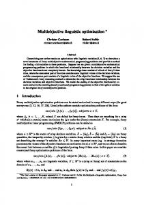
2.4 2.2 X: 223.7 L o ad Y: 12292 decre X: 223.7 ases 2 Z: 2.106 Y: 8965 Z: 2.136 1.8 X: 522 1.6 Y: 12292 Z: 1.211 1.4 1.2 X: 522 Y: 5268 1 X: 223.7 Z: 1.062 Y: 5268 14,000 Z: 1.304 12,000 600 X: 443.5 500 Spe 10,000 Y: 5638 ed Z: 1.058 400 (r/m 8,0006,000 ) 300 in) r (kW 200 Powe
Figure 7: “Load sharing map” of the reference design.
4.1. Objective Function. According to the previous section, the load sharing coefficient of a split torque transmission system changes greatly with different operating conditions, and the law of changing is complicated. Therefore, in order to obtain better load sharing from a system point of view, multiple operating conditions have to be taken into consideration. Considering the average case, the first objective function is promoted by minimizing the root mean square of load sharing coefficient under a wide range of operating conditions (possible operating conditions): input power varying from 223.7 kW (60% of 𝑃in ) to 522 kW (140% of 𝑃in ) and input speed varying from 5268 r/min (60% of 𝑛in ) to 12292 r/min (140% of 𝑛in ). When designing a gear transmission, light weight and safety are always important design targets. Safety is always measured by safety factors of contact fatigue strength and bending fatigue strength [24]. Therefore, the second and the third objective functions can be promoted by minimizing the total system mass and maximizing the total safety factors. To sum up, the whole objective functions are expressed as min 𝑌1 = 𝑘𝑙𝑠,RMS , 6
min 𝑌2 = ∑𝑀𝑔𝑖 ,
(23)
𝑖=1
min 𝑌3 = − ∑ 𝑆 = − (𝑆𝐻1 + 𝑆𝐻2 + 𝑆𝐹1 + 𝑆𝐹2 ) , stiffness of both paths decrease sometimes, compared to the errorless mesh stiffness. It means the gear tooth of both paths does not always fully contact over the whole theoretical contact line. Therefore, contact length and mesh stiffness cannot be predicted before the nonlinear model is solved. Besides, the phase difference of mesh stiffness can be found easily in the figure. The load sharing coefficient 𝑘𝑙𝑠 under different power and speed is evaluated as is illustrated in Figure 7. It can be seen that the “load sharing map” (curved surface of load sharing coefficient 𝑘𝑙𝑠 under different operating conditions) is complicated, which comes from the nonlinearity of the split torque transmission system. The evaluated load sharing coefficient 𝑘𝑙𝑠 varies from 1.058 to 2.136, with input power varying from 223.7 kW to 522 kW and speed varying from 5268 r/min to 12292 r/min. The root mean square (RMS) of load sharing coefficient 𝑘𝑙𝑠 is 1.391. From a global point of view, the load sharing coefficient 𝑘𝑙𝑠 increases with the speed increasing and power decreasing, which correspond with [6]. The mesh load of the gear pair is so little under the condition of high speed and light power that the elastic deformation is not large enough to offset the initial deviations at all the contact points. However, it is noteworthy that the law of
where 𝑘𝑙𝑠,RMS is the RMS of load sharing coefficient (L-S-C RMS) under the possible operating conditions, 𝑀𝑔𝑖 is the mass of gear 𝑖, 𝑆𝐻1 , 𝑆𝐻2 are the safety factor of contact fatigue strength of first and second stages, and 𝑆𝐹1 , 𝑆𝐹2 are the safety factor of bending fatigue strength of first and second stages. Here only the mass of gears is considered in the total mass of the system. The safety factors of gear pairs can be evaluated according to ISO6336; it will not be discussed in detail here. However, the calculation of gear mass is a problem; for the method to calculate gear mass is associated with its wheel structure. Generally there are three types of wheel structure: solid type, panel type, and spoke type. The reason to adopt different types of wheel structure is reducing weight: as the gear gets larger the more percentage of mass is removed from the wheel. Here the light weight coefficient 𝜂 is introduced to measure the extent of light weight, and then the gear mass 𝑀𝑔𝑖 can be calculated by ∗ 𝑀𝑔𝑖 = 𝜂𝑖 𝑀𝑔𝑖 2
𝑖 = 1, 2, . . . , 6,
(24)
∗ = 𝜌(𝜋/4)𝑏𝑖 𝑑𝑖 is the solid mass of gear 𝑖, with 𝜌: where 𝑀𝑔𝑖 the material density, 𝑏𝑖 : the tooth width of gear 𝑖, and 𝑑𝑖 : the pitch diameter of gear 𝑖.
8
Mathematical Problems in Engineering
The introduction of light weight coefficient 𝜂 unifies the different methods to calculate gear mass under different wheel structures, and the difference of three types of wheel structure is presented by varying the value of 𝜂. The type of wheel structure is decided by the tip diameter 𝑑𝑎 , so the value of 𝜂 is directly related to the tip diameter 𝜂 = 𝜂(𝑑𝑎 ). According to wheel structure design criteria, 3D parameterized model of a spur gear is created in CATIA V5 system. A series of gear models are created by varying the tip diameter 𝑑𝑎 in a wide range and the masses of them are measured in CATIA V5 system, and then the values of 𝜂 for gears with different tip diameters can be calculated. In the process of optimization, the value of 𝜂 for a gear is obtained by interpolating according to its tip diameter. The values of the three objective functions of the reference design are evaluated: the root mean square of load sharing coefficient 𝑘𝑙𝑠,RMS is 1.391, the system mass is 40.910 kg, and the total safety factors is 8.966.
second stages, and 𝐻 is the center distance between input and output shafts. The function round(⋅) here means round ⋅ to the nearest integer.
4.2. Designing Variables. There are a lot of designing parameters in a split torque transmission system; some of them are independent while others are not. Picking up appropriate parameters as the designing variables is the prerequisite for optimization design. The special arrangement of the split torque transmission leads to the special mounting condition: the proportioning of gear tooth has definite interrelation with the two shaft angles [2]. Once the proportioning of gear tooth and the two shaft angles are determined, the center distances of the two stages are determined at the same time, which are restricted to the center distance between input and output shaft. Therefore, the modules of the two stages can hardly be the standard value. In other words, in order to guarantee the correct arrangement of a split torque transmission system, the standard of modules has to be sacrificed. Based on the above considerations, the designing variables selected here includes the gear ratio of the first stage 𝑖1 , the pinion tooth number of the first and second stages 𝑍1 , 𝑍4 , the helix angle of the first stage 𝛽𝑏1 , and the two shaft angles Φ1 , Φ2 , as expressed in (25):
where 𝑖1 , 𝑍1 , 𝑍4 , 𝛽𝑏1 , Φ1 , Φ2 with the subscripts min and max are the boundaries of design variables, which are determined empirically according to the initial design.
𝑇
X = {𝑖1 , 𝑍1 , 𝑍4 , 𝛽𝑏1 , Φ1 , Φ2 } .
(25)
Other parameters can be evaluated by 𝑖2 =
4.3. Constraints 4.3.1. Boundary Constraints. The design variables meet the following constraints: 𝑖1,min ≤ 𝑖1 ≤ 𝑖1,max , 𝑍1,min ≤ 𝑍1 ≤ 𝑍1,max , 𝑍4,min ≤ 𝑍4 ≤ 𝑍4,max , 𝛽𝑏1,min ≤ 𝛽𝑏1 ≤ 𝛽𝑏1,max , Φ1,min ≤ Φ1 ≤ Φ1,max , Φ2,min ≤ Φ2 ≤ Φ2,max ,
4.3.2. Performance Constraints. (i) Contact and bending fatigue strengths should be below the allowable values: 𝜎𝐻1,2 ≤ [𝜎𝐻1,2 ] ,
where 𝜎𝐻1,2 is the contact stress of the first and second stages, [𝜎𝐻1,2 ] is the allowable contact stress of the first and second stages, 𝜎𝐹1,2 is the bending stress of the first and second stages, and [𝜎𝐹1,2 ] is the allowable bending stress of the first and second stages. (ii) First stage gears should not interfere with each other: 𝑚1 (𝑍2 + 2ℎ𝑎∗ )