Localization Technique for Automated Tracking of Construction Materials Utilizing Combined RF and Ultrasound Sensor Interfaces Mirosław J. Skibniewski1 and Won-Suk Jang2 1
Professor and A. J. Clark Chair, Department of Civil and Environmental Engineering, University of Maryland, College Park, MD 20742-3021; PH: 301-405-9364; Fax: 301405-2585; email:
[email protected] 2 Ph. D. Candidate, Department of Civil and Environmental Engineering, University of Maryland, College Park, MD 20742-3021; PH: 301-405-9364; Fax: 301-405-2585; email:
[email protected]
Abstract This paper introduces a prototype framework for automated material tracking (AMTRACK) system. A new ZigBee-based localization technique with hybrid sensor interfaces – combination of radio frequency and ultrasound devices – is presented to improve the accuracy and efficiency of materials tracking. AMTRACK system will provide a potential to increase location accuracy by eliminating multipath property of radio signal propagation. In addition, mesh network capacity of the ZigBee standard will leverage the applicability of the AMTRACK prototype in complex construction projects. Keywords: ZigBee standard, sensor network, object localization, radio frequency and ultrasound-based sensing, component tracking
Introduction Advancements in low power microelectronic devices and sensor network technologies provide the capability to automate and integrate individual tasks for tracking and monitoring in construction job site. Past research efforts have been put to improve the materials management practices and to increase the efficiency in field data acquisition using emerging technologies, such as RFID and GPS. Even though RFIDs provided an advanced material tracking method when compared with previously available technologies, e.g. bar codes, practical application of RFID in construction has been limited due to a short coverage range and expensive RFID readers. GPS combined with RFID can improve the applications on construction sites, but stand-alone GPS’s also have some drawbacks related to multipath and signal masking in highly dense areas populated with buildings and other structures. This paper introduces a new prototype framework for automated tracking of construction materials on the job site. This framework will be implemented through a localization technique with hybrid sensor interfaces – combination of radio frequency and ultrasound devices – to improve the accuracy and efficiency of materials tracking. For more flexible and expandable topology formulation, our investigation also introduces the network platform utilizing the ZigBee standard, which has emerged as a superset of the IEEE 802.15.4 standard for industrial monitoring and control. A hybrid sensor-based ZigBee network will provide a potential to increase location accuracy by eliminating multipath property of radio signal propagation. In addition, mesh network capacity of the ZigBee standard will leverage the applicability of this prototype to a complex construction site in an energy-efficient way. The Proceedings of the ASCE International Workshop on Computing in Civil Engineering, July 24-27, 2007, Pittsburgh, PA
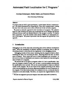
Background Location tracking technique has fostered a growing interest in mobile systems implementing ubiquitous computing environments [Skibniewski and Jang, 2006]. In construction environment, the system design and development for estimating location and spatial information is challenging task because of management complexity, large scale system and harsh nature of wireless communication. Furthermore, there exist a variety of localization techniques that determine the location of objects or people in different environmental circumstances, e.g. building offices, industrial job sites, metropolitan areas, or open outdoor spaces. Thus, it is important to examine the different characteristics of each technique for appropriate deployment to the environment relevant to construction sites. Olivetti Research Laboratory, now AT&T Cambridge, has developed the Active Badge indoor location system that consists of a cellular proximity system using diffuse infrared technology [Want et al., 1992]. Small infrared badge attached to mobile objects emits a globally unique identifier, and this data is sent to the application programming interfaces, shown in Figure 1. Active Badges, however, have a limitation on location with the environment of fluorescent lighting or direct sunlight due to the emissions of spurious infrared generated from these light sources [Hightower and Borriello, 2001]. In addition, effective coverage range has several meters, which limits communication area to a small- or medium- sized room.
Figure 1: Active Badge [AT&T Laboratories Cambridge]
Figure 2: Active Bat [AT&T Laboratories Cambridge]
For more accurate physical positioning over Active Badges, Active Bat location system has been developed by AT&T researchers [Harter et al., 1999]. Active Bat uses an ultrasound time-of-flight lateration technique, in which a Bat emits an ultrasound pulse to a grid of ceiling-mounted receivers to measure the time interval from reset to ultrasound pulse arrival, shown in Figure 2. The Active Bat system shows within 9 cm resolution of Bats’ position for 95 percent of measurements, and it can also compute orientation information based on predefined placement of Bats. However, there are some disadvantages that include difficulty of deployment, cost, and limited scalability because the system requires large scale of fixed-sensor infrastructure and precise placement of sensors. The Cricket Location-Support System, complementing the Active Bat system, has been developed by MIT Computer Science and Artificial Intelligence Laboratory, shown in Figure 3 [Priyantha et al., 2000]. Localization technique used in Cricket system utilizes the radio frequency signal not only for synchronization of the time measurement, but also to delineate the time region during which the receiver should consider the ultrasound it receives. Like the Active Bat system, cricket uses ultrasonic time-of-flight The Proceedings of the ASCE International Workshop on Computing in Civil Engineering, July 24-27, 2007, Pittsburgh, PA
data and a radio frequency control signal, but a grid of fixed ceiling sensor is not required because the receivers perform the timing and computation function. One advantage of the Cricket system is that it does not rely on any centralized control system or explicit coordination mechanism between beacons. Additionally, the system provides information to devices regardless of their type of network connectivity; and each Cricket device is made from off-the-shelf components and costs less than $10. However, timing and processing both the ultrasound pulses and RF data may increase computation and power burden on the mobile receivers, and it is not easy to monitor the performance of receivers’ performance due to decentralized management [Hightower and Borriello, 2001].
Figure 3: A few different Cricket units. From left to right: v1, v2, v2 done jointly with Crossbow, and a compass daughter board. [Balakrishnan et al, 2003]. The remaining majority of localization techniques are based on the received signal strength indicator (RSSI) due to it’s widely availability in wireless radio signal communication [Lymberopoulos et al, 2006]. Especially, RSSI-based localization has an advantage that utilization of the same radio hardware for both communication and localization would make it possible to provide efficiency in simple design framework over a specific localization infrastructure – such as the ones using directional antennas or same transmission signal, and separate design of ultrasound or infrared [Elnahrawy et al., 2004]. Table 1 summarizes the characteristics of different RSSI-based localization techniques. However, RSSI-based localization has a critical limitation that has been observed in the characteristics of radio signal propagation. Since raw RSSI does not provide enough accuracy in localizing the mobile objects to be used in a practical application, the distance prediction requires additional investigation of the probability method or learning-based localization algorithm [Lymberopoulos et al., 2006]. The main factor associated with the inaccuracy is identified as the multipath propagation. Multipath is the propagation phenomenon that results in two or more propagation paths between the sensor and the receiving antenna. The level of inaccuracy inherited from the physical properties of radio signal increases as the chance of reflections or scatterings of signal from unwanted obstacles becomes higher, such as indoor environments where signals travel with multiple obstructions along the way. The localization error observed in the RSSI-based techniques shown in Table 1 illustrates that most of the errors range from 15 ft to 25 ft for an indoor system. While a construction site can be an outdoor environment where the chaotic properties of signal propagation can be significantly lessened in comparison with an indoor site environment due to less obstruction, there are still physical limitations of a multipath in signal propagation because of typically complicated layouts of both indoor and outdoor construction sites.
The Proceedings of the ASCE International Workshop on Computing in Civil Engineering, July 24-27, 2007, Pittsburgh, PA
Table 1: Characteristics of different RSSI-based localization techniques [Lymberopoulos et al., 2006]. Technique
Design Approach
Ecolocation Probability Grid Radar MoteTrack LEASE
802.11b MICA2
Testbed Dimensions 26 × 49(ft) (Indoor) 410 × 410(ft) (Outdoor) 42.9 × 21.8(m) 18751 ft2
15 ft 13 ft
802.11b
225 × 144(ft)
15 ft
Technology
Constrained based approach applied on the ordered sequence of raw RSSI data Probabilistic. RSSI values are used to estimate the one-hop distance in a grid RSSI fingerprint map RSSI fingerprint map Online Fingerprinting and signal propagation modeling
MICA2 MICA2
Location Error 10 ft 66 ft
Bayesian Indoor Positioning System
Learning Based
802.11b
225 × 144(ft)
20 ft
Stochastic Indoor Location System
Optimal positioning of a given number of clusterheads with respect to the location-detection performance
N/A
N/A
N/A
Monte Localization
Learning based with signal strength map
802.11b
N/A
7.2 ft
Bayesian networks
802.11b
224 × 96(ft) (Indoor)
20 ft
Nibble
Carlo
AMTRACK Architecture Automated Material Tracking (AMTRACK) architecture described in this paper employs an new method of eliminating the multipath, and ensures accurate measurement of distance for improved performance of mobile object tracking. The AMTRACK system is composed of network and controller specifications to implement the localization algorithm for a material tracking system. Network specification defines the network protocols and device requirements, and controller specification defines hardware functions to translate the raw data into distance measurement. A ZigBee module has both network and controller specifications as well as additional ultrasound transducer, and it functions as a unique set of tracking device. (1) Query and response pulse based on TOF Two alternative approaches are introduced to estimate the distance of a ZigBee sensor from Data Query ZigBee Time-of-Flight Sensor ZigBee beacon based on time-ofResponse RFI Router (RF or Ultrasound) flight method: one uses a radio Beacon frequency signal as both query and Data Packet response pulse; and the other Discretized scheme uses the RF as a query Signature Pulse pulse and ultrasound as a response Figure 4: Description of combination of signature pulse (see Figure 4). The role of pulse: two alternative approaches (RF and the query pulse is to call a particular ultrasound) ZigBee sensor with a discretized signature pulse signal to send a response pulse for measuring the distance between beacon and sensor. The RF query pulse contains information about the sensor’s ID, the response schedule and multiple access indicators. Pulse type signal is used to differentiate the original signal and multipath by recognizing the first arrival time of pulse. Since frequency and signature shape will not be changed or distorted unless it is RF or Ultrasound Transceiver
Amp.
T
The Proceedings of the ASCE International Workshop on Computing in Civil Engineering, July 24-27, 2007, Pittsburgh, PA
reflected or refracted, the sensor’s distance can be measured by time-of-flight ensuring the elimination of multipath property of the radio signal without interference. Once a particular ZigBee sensor receives a query pulse, it performs required signal processing according to the command information received from beacon and then it generates response pulse to be sent out to ZigBee beacon. First arrival of response pulse is then differentiated by channel access method, such as time division multiple access or frequency division multiple access. Travel time of pulse signal as well as processing time of the ZigBee sensor is then converted into distance. Once the beacon recognizes both sensor’s ID (by RFI) and distance (by travel time of pulse signal), the geographic coordination of the sensor can be obtained by trilateration method that uses two or more referenced points to determine the coordination of the sensors.
(2) Measurement of the distance by RF signal The advantage of using RF signal in both query and response signal can be described that distance measuring scheme can be implemented in the same ZigBee hardware, which makes the device design simple and small without additional device installation. Since ZigBee specification with 2.4 GHz provides 16-channel allocation scheme, one channel can be used in general data communication and another channel can be allocated for the use of distance measurement. Another advantage includes the flexibility of communication method due to the ability of RF modulation in response pulse. However, RF-based response pulse may cause large measurement error due to very fast speed of RF signal compared with the microcontroller’s operation time. In order to conduct a more detailed performance study of the system, assume that 1 meter measurement accuracy is desired to estimate the distance from the beacon to sensor, and also assume that desired maximum distance of sensors from the beacon is about 200 meters. As shown in Figure 5(a), we assume that the timer is implemented by a counter that counts up with a fixed clock frequency fc. The timer with a fixed clock frequency should have the resolution of 200 divisions in order to satisfy the resolution of 1 meter, so it needs to have at least 8 bits. On the other hand, each increment of timer operation happens in time 1 / fc and accuracy of 1 meter is possible if 1 / fc is smaller than the round trip time of the RF signal for an object in distance of 1 meter. This will lead us to Equation (1): 8
fc ≥
3 × 10 m / s 2 ×1 m
= 150 MHz
(1)
The calculation in (1) shows that an increment of 1 / fc = 6.6 ns causes a 1 meter error in estimation of the distance from the beacon. One possible shortcoming is that this system will cause increased error in measurement of the distance if the undesirable errors and processing delays happen in scheduling of the sensors. All operations of a sensor are performed according to an on-board oscillator that generates timing of the internal processor of the sensor. The frequency of such an oscillator is typically 10-100 MHz for current sensor technologies. If the clock frequency of the microprocessor module of a sensor is fp = 20 MHz, each instruction time of the digital clock generated in microprocessor frequency can have 1 / fp = 50 ns to respond to the query of the beacon after receiving it. Hence if the received query does not match the exact point of rising and falling edges of digital clock, microprocessor’s operation should wait next cycle to be triggered because each process operation is implemented once per each instruction cycle (see Figure 6). This means that the worse case of delay in microprocessor’s operation The Proceedings of the ASCE International Workshop on Computing in Civil Engineering, July 24-27, 2007, Pittsburgh, PA
may be up to one instruction time, 50 ns, to generate a response pulse, and this processing time delay of 50 ns generates almost 5.7 meters error in measurement of distance. Router
Sensor
d
Router
d
Query (RF)
Query(RF)
Response (Ultrasound)
Response (RF) Timer
Sensor
fc
Timer
fc
(a) (b) Figure 5: Distance estimation from the router based on (a) the round trip time of the RF signal and (b) combination of RF signal and ultrasound signals The error generated by RF round trip time delay in distance estimation of a sensor from the beacon is attributed to the result of very fast speed of RF signals in the space compared with the microprocessor’s clock speed. A sensor device with higher clock frequency, such as over 1/6.6 ns = 151 MHz, may satisfy threshold of 1 m accuracy, other shortcomings that include such as increased device cost and power may be incurred in the practical design of sensor. In order to resolve this issue, we study a second scenario, in which an alternative ultrasound signaling is used to measure distance of sensors to the router.
Figure 6: Operation delay in digital clock cycle when a signal is received at time TR
(3) Measurement of the distance by combination of RF and ultrasound signals The general system architecture using RF and ultrasound signals is similar to previous section, but we introduce a different scheme that employs an ultrasound signal as a response pulse for a more accurate measurement of distance, shown in Figure 5(b). Two major differences in this method when compared with the previous one can be identified. First, the speed of ultrasound signals is the speed of sound, about 340 m/s, which is significantly smaller than the speed of light. The second difference from the scheme in the previous section is that the ultrasound signal does not have any form of modulation, so it is impossible to carry any of digital information for data communication. In order to perform similar calculations to those in previous section, and under similar assumption of measurement of distance up to 200 meters with 1 meter accuracy, we need the timer to be an 8-bit timer with the clock frequency (given by Equation (2): fc ≥
340 m / s 1m
= 340 Hz
(2)
The Proceedings of the ASCE International Workshop on Computing in Civil Engineering, July 24-27, 2007, Pittsburgh, PA
As shown in Figure 5(b), the RF query signal travels with the speed of light in the forward direction and ultrasound signal with the speed of sound in the backward direction. It is important to note that it is possible to ignore the component of the delay introduced by the propagation delay of RF signal in the query pulse, and the small processing or scheduling delay at the sensor. This is because the speed of light is about one million times faster that the speed of ultrasound. Therefore the dominant component of the round trip of the signal is the one-way traveling time of the ultrasound signal from the sensor to the beacon. In this case, about 3 ms increment in the value of round trip time is generated by a 1 meter increase in the distance of the sensor from the beacon. This increment of travel time is much larger than the typical travel time of RF between sensor and the beacon (about 1.3 μs for maximum distance of 200 meters), or the processing and scheduling delays at the microprocessor of the sensor (50 ns in the previous example). Therefore, it is expected that the accuracy of distance measurement using the combination of RF and ultrasound would improve performance when compared with the use of RF signal alone. Another advantage of this combined technique is that the distance measurement scheme in one-way travel of ultrasound signal utilizes a direct signal that is transmitted and received from/to beacons and sensors, and it does not admit the reflected ultrasound wave for measuring the time-of-flight. Thus, one-way signal propagation ensures larger traveling range with the same power, and it is possible to prevent any signal distortion of signature pulse that might occur during wave reflection from the object of interest. One issue with regard to the system based on the combination of RF and ultrasound signals is that travel speed of ultrasound signal depends largely on the ambient parameters such as temperature and pressure, especially in an outdoor environment of a construction site. Such dependences can be taken into consideration by calibrating the variation of these parameters with additional environmental monitoring sensors, such as a temperature and pressure sensor embedded in the system.
Conclusion This paper introduced a new localization technique for automated materials tracking in construction sites. To overcome the limitations of RFID- and GPS-based technologies already introduced into current construction site practices, an idea to combine radio frequency and ultrasound was presented with the aim of producing more accurate positioning performance. An initial feasibility analysis showed that combination of radio frequency and ultrasound may provide a better performance in measurement accuracy than using RF alone. Based on the associated components of network specifications and the tracking method described in the paper, we plan to continue the development of an algorithm for frequency modulation and scheduling. In addition, we will implement the device design for practical application to construction sites aiming at improvements in process performance and project cost. References Active Badge, AT&T Laboratories Cambridge, available online at: http://www.cl.cam.ac.uk/research/dtg/attarchive/thebadge.html >(Nov. 22, 2006)
The Proceedings of the ASCE International Workshop on Computing in Civil Engineering, July 24-27, 2007, Pittsburgh, PA
Active Bat, AT&T Laboratories Cambridge, available online at: http://www.cl.cam.ac.uk/research/dtg/attarchive/bat/flatBatInside.jpg >(Nov. 22, 2006)
Balakrishnan, H., Baliga, R., Curtis, D., Goraczko, M., Miu, A., Priyantha, B., Smith, A., Steele, K., Teller, S. and Wang, K. (2003), “Lessons from Developing and Deploying the Cricket Indoor Location System.” MIT CSAIL, http://nms.lcs.mit.edu/cricket/, November 2003, (preprint). Elnahrawy, E., Li, X., and Martin, R. M. (2004). “The Limits of Localization using Signal Strength: A Comparative Study.” Proceedings of Sensor and Ad-Hoc Communications and Networks Conference 2004 (SECON’04), October 2004, Santa Clara, CA Harter, Andy, Hopper, Andy, Steggles, Pete, Ward, Andy and Webster, Paul (1999). “The Anatomy of a Context-Aware Application.” Proceedings of 5th International Conference on Mobile Computing and Networking (MOBICOM’99), ACM Press, Seattle, WA, August 15-20, 59-68 Hightower, Jeffrey and Borriello, Gaetano (2001). “Location Systems for Ubiquitous Computing.” IEEE Computer, 34 (8), 57-66 Lymberopoulos, D., Lindsey, Q., and Savvides, A. (2006). “An Empirical Analysis of Radio Signal Strength Variability in IEEE 802.15.4 Network using Monopole Antennas.” Technical Report 050501, Embedded Networks and Applications Lab (ENALAB), Yale University, New Haven, CT Priyantha, Nissanka B., Chakraborty, Anit and Balakrishnan, Hari (2000). “The Cricket Location-Support System.” Proceedings of 6th International Conference on Mobile Computing and Networking (MOBICOM2000), ACM Press, Boston MA, August 6-11, 32-43 Skibniewski, M. and Jang, W.-S. (2006). “Ubiquitous Computing: Object Tracking and Monitoring in Construction Processes Utilizing ZigBee Networks.” Proceedings of 23rd International Symposium on Automation and Robotics in Construction (ISARC), Tokyo, Japan, October 3-5 Want, Roy, Hopper, Andy, Falcão, Veronica and Gibbons, Jonathan (1992). “The Active Badge Location System.” ACM Transactions on Information System, 10 (1), 91-102
The Proceedings of the ASCE International Workshop on Computing in Civil Engineering, July 24-27, 2007, Pittsburgh, PA