and notice is given that copying is by permission of the Association for .... for solving the engineering change problem. Note that since the amount of design modi ...
Logic Synthesis for Engineering Change Chih-chang Lin University of California, Santa Barbara
Kuang-Chien Chen Fujitsu Laboratories of America, INC.
Shih-Chieh Chang 1 Synopsys Inc.
Malgorzata Marek-Sadowska University of California, Santa Barbara Kwang-Ting Cheng University of California, Santa Barbara
Abstract | In the process of VLSI design, speci cations are often changed. It is desirable that such changes will not lead to a very di�erent design so that a large part of engineering e�ort can be preserved. We consider synthesis algorithms for handling such engineering changes. Given a synthesized network, our algorithm modi es it minimally to realize a new speci cation.
1 Introduction
In a typical VLSI design process, speci cations are often changed in order to correct design errors, or to meet certain design constrains such as area, timing and power consumption. Since a lot of engineering e�ort may already have been invested (e.g., the layout of a chip may have been obtained), it is desirable that such changes in speci cation will not lead to a very di�erent design and a large part of the engineering e�ort can be preserved. This is usually called the engineering change (EC) problem. Since synthesis tools usually perform global transformations (e.g., sharing of modules) to achieve good quality results, small and local changes in the speci cation could have global e�ects and produce a very di�erent network. Realizing this fact, designers usually have to manually modify the synthesized network to realize changes in the speci cation. Such practice not only increases the chance of introducing inconsistencies between the higher{ level speci cation (e.g., VHDL) and the nal network, but also it is an error{prone process that often fails because the correspondence between the speci cation and synthesized network cannot be easily identi ed (e.g., a signal in the VHDL speci cation may not appear as a signal in the synthesized network). Therefore, there is an urgent need for synthesis algorithms which can handle engineering changes e�ectively. 32nd ACM/IEEE Design Automation Conference Permission to copy without fee all or part of this material is granted, provided that the copies are not made or distributed for direct commercial advantage, the ACM copyright notice and the title of the publication and its date appear, and notice is given that copying is by permission of the Association for Computing Machinery. To copy otherwise, or to republish, requires a fee and/or specific permission. 1995 ACM 0-89791-756-1/95/0006 $3.50
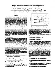
Example 1 Figure 1.(a) shows a network which repre-
sents the original speci cation. After applying logic transformation and optimization procedures [1, 2, 3] on it, the resulting network is shown in Figure 1.(c). Suppose the speci cation in Figure 1.(a) is modi ed by changing p5 from an XOR gate to an AND gate (Figure 1.(b)). After applying the same synthesis procedures, we obtain a network shown in Figure 1.(d). Although the change in speci cation arises from a local modi cation, general synthesis procedures do not localize such a change and the networks in Figure 1.(c) and Figure 1.(d) are quite di�erent. One can modify the network in Figure 1.(c) directly, and obtain a network similar to Figure 1.(c), yet realizing the new speci cation in Figure 1.(b). Such manual EC technique, however, cannot be easily applied in this case. This is because the signal corresponding to gate p5 in Figure 1.(a) is no longer available in the optimized network Figure 1.(c). Therefore, although we know the change arises from the modi cation of p5, it is di�cult to tell in Figure 1.(c) where and how the modi cations should be done. A good synthesis procedure which considers engineering changes will be able to modify the network in Figure 1.(c) minimally, and retain functional equivalence to the speci cation in Figure 1.(b). By applying our algorithms on the network in Figure 1.(c), the network in Figure 1.(e) is obtained, di�ering from the network in Figure 1.(c) in that the gates k0; k1 and k2 are removed and a gate k3 is added. 2
Note that changes made at high levels can potentially introduce large changes in the nal design. For example, suppose a design is described in terms of its state transition graph, and modi cations were made resulting in changes in the number of states and state transitions. Then, during synthesis, state encoding di�erent from the original encoding may be used, potentially leading to a very di�erent network. Therefore, it should not be expected that engineering changes can always be done with very few modi cations. In this paper, we will concentrate 1 this work was conducted when the author was in University of California, Santa Barbara.
y0
conn2 . Moreover, there are O(N 2) such possible substitutions, where N is the number of gates in the network. It would be time{consuming to do an explicit search on the whole network. To search heuristically for indirectly substitutable connections, a technique used in a multi{level logic optimizer [2] can be employed. Given a conn2, [2] restricts the search to conn1's, where conn1 's are redundant connections and D1 's are dominators 3 of D2 . After adding conn1 (a redundant connection) to the network, conn2 can be removed if it becomes redundant, therefore conn1 is indirectly substituting conn2 . We will give an example in Section 4.2. For more details, please refer to [2, 3]. o be the original speci In the following discussion, let S cation and C o a corresponding synthesized network. Suppose S n is a new speci cation resulting from engineering changes. Then, the goal of logic synthesis for engineering changen is to synthesize a network C n such thato it real-n izes S and the structural di�erences between C and C are minimized. Ino then remainder of the paper, we shall simply refer to S (S ) and C o (C n) as the old (new) speci cation and network, respectively.
y0
x1 x3 x4
x1 x3 x4 x1
x5
x1
y2
p5
x2
x5
x0
y2
p5
x2 x0 y1
y1
(a) the original specification. x1
(b) a new specification. y0
y0
x3 x4
x1
k1
x2 x0
k2
k0
t p1
x3 x4
y2
y2 x5
x2 x0
x5
y1 y1 x1
(d) a circuit synthesized from the new specification in (b).
(c) a circuit synthesized from the specification in (a). x1
y0
x3 x4 x2 x0
t
k3
3 Previous Work
y2
In [5], Cn o and C n are synthesized independently from o S and S , and then a post{processing step is performed too identifyn the correspondence between pins oand gates of C and C . This method is e�ective when C and C n are
x5 y1 x1
(e) a circuit synthesized by applying EC algorithm.
structurally similar, but this is often not the case with existing logic synthesis algorithms which tend to change substantially the structure of the networks. In [6, 7], the idea was to leave the old network C o totally unchanged, and to rectify the speci cation changes by attaching pre{logic and post{logic networks to the primary inputs and outputs of C o . Boolean relation based algorithms were developed to derive the functions of the pre{ and post{logic. This approach is useful when changes are made at a later stage of the design process. However, the pre{ and post{logic added may be too large to be useful, and it is not suitable in situations where the internal structure of the old network can be modi ed. In [8], a novel approach is proposed which explores the structural equivalence between the S oo and S no , and the functional equivalence between the S and C . Using these structural and functional equivalence, [8] establishes a mapping between the signals in C o and the ones in S n . Then, this mapping information is used to guide an ATPG{based logic substitution process. This method is computationally e�cient. However, its e�ectiveness depends on the amount of the functional equivalence between the speci cations and C o . The error diagnosis problem can be viewed as an engineering change problem if the appropriate networks are interpreted as follows. C o is supposed to implement the n speci cation S and contains an o implementation error such that it actually implementsnS and S o = S n . Therefore, the correct speci cation S is now the new speci -
Figure 1: An example of the EC problem. on the core problem of the engineering change, i.e., handling functional speci cation changes for combinational networks .
2 Basic De nitions
For simplicity, we assume all the gates in the network realize the AND, OR, NAND or NOR functions. Let conni = (Si ; Di ) be a connection, where Si is the source node and Di is the destination gate. We use fconn (X) to represent the function of conni with respect to the primary inputs X. A connection is called redundant if the function of the network remains unchanged after adding or removing it. A connection conn2 = (S2 ; D2) is called substitutable by another connection conn1 = (S1 ; D1) if the function of the network remains unchanged after adding conn1 and removing conn2 . In the case where D1 equals to D2 , conn2 is called directly substitutable by conn1. For given connections conn1 and conn2, the exact requirement of conn2 being directly substitutable by conn1 is [4] fconn1 (X) fconn2 (X) ODC(conn2); where ODC(conn 2 ) represents the observability don't{ cares of conn2 2 . In the case where D1 is di�erent from D2 , conn2 is called indirectly substitutable by conn1. There is no simple way to tell if conn1 can indirectly substitute conn2 except by explicitly checking the equivalence of two networks, one with conn1 and the other with i
�
2
�
6
3 A node A is called a dominator of another node B if every path from B to the primary outputs passes through A.
In [4], fconn1 (X ) is called a permissible function of conn2 .
2
cation, and our goal is to modify C o into another network C n which implements S n correctly. In [9, 10, 11], error diagnosis and correction techniques were proposed based on a single{error model which assumed that the structural di�erence between C o and C n can be characterized as a single gate type change or a single wire mis{connection. In the following sections, we will discuss our approach for solving the engineering change problem. Note that since the amount of design modi cations needed for achieving speci cation changes is really unpredictable, a good approach needs to be able to complete the task even when a large modi cation is needed. At the same time, it should be able to keep the modi cations as small as possible.
Then, the di�erence between C o and S n can be recti ed by replacing fto (X) with ftn (X) if and only if the following condition holds: yin (X) � yio (X; t = ftn (X)) = 0; for 1 � i � k; (1) which is equivalent to
yin (X) yio (X; t = 0) ftn (X) yin (X) yio (X; t = 1); for 1 i k: (2) The function ftn (X) is an incompletely speci ed function �
�
�
�
�
whose on{set and o�{set are as follows:
fton (X) =
4 Synthesis Algorithms for EC
[k yn (X)
i=1
ftoff (X) =
As discussed in the previous section, the error diagnosis problem has a strong relationship to the EC problem. However, in error diagnosis, usually a simple single{error model is assumed. In EC problems, our experience shows that changes in speci cation can potentially result in diverse changes in a network, and it is often necessary to make multiple changes in the old network in order to realize a new speci cation. Therefore, to develop a robust algorithm for EC, we do not assume any error model and we do not limit the number of gates and connections that can be changed. The overall process of our EC algorithm can be divided into two major steps: 1) Identi cation of candidate signals which can rectify the di�erence between the old network and new speci cation, and also derive the target functions of those candidate signals. 2) Synthesis of the target functions by utilizing existing logic of the old network. To realize the new speci cation with minimal modi cations, Step 1 should identify as few signals as possible. Furthermore, the synthesis algorithms in Step 2 have to be powerful enough so that the target functions can be realized using as few gates as possible.
i
�
yio (X; t = 0); and
[k yn(X)
i=1
i
�
yio (X; t = 1):
Essentially, Lemma 1 states that each output yi poses a constraint on the t and when all the constrains can be satis ed simultaneously, the signal t is a candidate signal. Note that information of the network's structure (e.g. intersection of fanin cones, dominator sets [11], etc.) can be used to trim down the search space and an OBDDbased [12] method can implement Lemma 1 e�ciently. For example, in Figure 1.(c), we can identify the connection t = (k0; p1) as the candidate signal, and its target function is as follows: fton (X) = x0x1x2 x5; and ftoff (X) = (x0 + x1 + x2)x5 : Once a candidate signal t is found, we realize its target function by a subcircuit. The size of the subcircuit can be very small (e.g., a single gate) or it could be quite large, depending on both the target function and synthesis algorithms, and this is where the quality of EC solutions is determined. If many outputs of the old network and new speci cation are di�erent, the chance of nding a candidate signal which can rectify all of them becomes small, and thus, we need to consider the possibility of changing the functions of many signals. In our approach, when a single candidate signal cannot be identi ed, a divide{and{ conquer strategy is applied to overcome the problem. Let POerror (POcorrect ) denote the set of outputs which are di�erent (equivalent) in the old network and new speci error cation. During divide{and{conquer step, the set POerror is heuristically partitioned into two sub{groups (PO 1 and PO2error ) and then each sub{group is recti ed sequentially. When searching for aerror candidate signal to rectify the erroneous outputs in POi error, we have only to check Lemma 1 on the outputs in POi and POcorrect. Thus, the possibility of nding such a signal increases. We developed a simulated annealing based approach to nd a partition such that the intersection of fanin cones in each sub{group is maximized to increase the chances of nding candidate signals. Using this divide{and{conquer scheme, we can always nish the search of candidate signals.error In the worst case, we have to rectify each output in PO individually.
4.1 Identi cation of Candidate Signals
To identify candidate signals which can potentially rectify the di�erence between the old network and new speci cation, an error location technique discussed in [10, 11] has been extended for use in our approach. In the old network C o , suppose a signal t with function fto (X) is selected (X is the set of primary inputs), we nt (X) such want to know if there exists a new function f that replacing the function of t by ftn (X) will yield a network which implements the new speci cation S n . The following lemma [10, 11] states the necessary and su�cient condition. Lemma 1 Let yioo(X) be the function of the ith output, o 1 i k, of C , and yi (X; t) nthe same function expressed in terms of X and t. Let yi (X) be the function of the corresponding ith output in the new speci cation S n . �
�
�
3
4.2 Synthesizing Target Functions for Can- The previous two approaches both try to realize the didate Signals target function by a single complex gate. It was found
experimentally that very often, although a candidate signal can be found, it cannot be realized by a single gate using the gate synthesis algorithms discussed above. It suggests that trying to realize the target function by just one gate is probably too restrictive, and a more general synthesis approach is still needed. The third approach, which is also the most general one, synthesizes a subcircuit Kt to realize fton (X) in terms of the primary inputs rst, and then this subcircuit is minimized by using existing logic of the old network C o . Two minimization techniques, one based on permissible functions [4], and one based on ATPG techniques [2, 3] were employed. In the permissible function based method, for each connection conn2 in the subcircuit Kt , we search for a connection conn1 in C o which can directly substitute conn2. If this happens, the connection conn2 and frequently also a large portion of its fanin cone in Kt can be removed. In the ATPG{based method [2, 3], the e�ort is on nding connections which can indirectly substitute a chosen connection in Kt . The goal here is to nd conn1, which when connected to conn2's dominators make the conn2 redundant and therefore removable.
As discussed in the previous subsection, an incompletely speci ed Boolean function represented by [fton (X); ftoff (X)] can be determined as a target function for a candidate signal t. Our goal is to synthesize a function ftn (X) [fton (X); ftoff (X)] using as few gates as possible, by fully utilizing the existing logic in C o . We examine several such algorithms in this subsection. The rst algorithm adopted in our approach is the RENO algorithm [13], which tries to synthesize a single complex gate to realize the target function. First, in RENO, a list of candidate cubes are generated using outputs of internal gates in C o . Each candidate cube when expressed in terms of primary inputs X covers a portion of fton (X) but none of ftoff (X). After generating a set of candidate cubes which can cover fton (X), the problem is transformed into the so{called sum{to{one subset problem which can be viewed as a generalized 2{ level minimization problem. The solution obtained will be a SOP form in terms of selected candidate cubes. Also, the quality of the synthesis result depends on the total number and choice of the candidate cubes. In our experiments, computation time is reasonable when the number of candidate cubes is less than 30. However, this number is usually not large enough to fully explore the synthesis possibilities. To enhance the gate synthesis algorithm, we developed another approach for single complex gate synthesis. In this approach, instead of generating candidate cubes explicitly, we used an image computation technique [14] to examine implicitly the candidacy of all the 3k cubes formed by a set of k internal signals g1; ; gk . The idea is as follows: a cube (formed by g1 ; ; gk ) is a candidate cube if and only if its function does not intersect the o�{ set ftoff (X). Since the image of the o�{set ftoff (X), with respect to g1; ; gk, represents cubes which intersect the o�{set, the complement of the image contains all the candidate cubes formed by theonk signals and they can be used to synthesize the on{set ft (X). 2
Example 2 Consider the irredundant network in Fig-
ure 2.(a). Suppose we are searching for indirectly substitutable connections of conn2 = (g1; g4). The idea is to nd a connection conn1 such that its addition to the network will make the connection conn2 redundant. To preserve the functionality of the network, we also have to make sure that the connection conn1 is redundant in the original network. For conn2 to be irredundant, the assignments fg1 = 0; c = 1; g7 = 0; f = 1g on the gates must be realizable by at least one input pattern. The constraint fg1 = 0g is called a justi cation constraint, while fc = 1; g7 = 0; f = 1g are propagation constraints. We have the propagation constraint, say g7 = 0, because the gate g8 is a dominator of conn2 and its input g7 is required to be zero to allow the value of conn2 propagate through the dotted line. Using these constraints, we conclude that g5 must be zero (because c = 1 implies g2 zero). Now if we connect g5 to g9, it will block the propagation of the value coming from conn2 through the dotted line and thus make the connection conn2 redundant. Before removing conn2 , we check if the connection conn1 = (g5 ; g9) is redundant. The answer is yes, thus, we can add conn1 and remove conn2. The result is shown in Figure 2.(b). 2
���
���
���
Lemma 2 The following formula computes all the candi-
date cubes formed by a set of k signals, G = fg1; � � � ; gk g:
candidate cubesg = imageG (ftoff (X)); where imageG () is a mapping from 2X to 2G . f
Compared with RENO, the image computation based method can examine more candidate cubes and thus obtain better results. In comparison to [10, 11], the image based method is more e�cient since all the minterms in terms of G are considered simultaneously and an OBDD{ based technique [14] can be used to achieve e�cient computation. However, it is still a very di�cult problem to choose an optimal set of k signals. We have developed heuristics in which the signals are incrementally added toonthe set G and conditionally rejected if the coverage of ft (X) does not increase.
Note that the justi cation and propagation constraints described above are only the necessary constraints. The example shows how to add a redundant connection to the network to violate the propagation constraints of a target connection. We can also apply the same technique to violate the justi cation constraints. These two kinds of substitution (direct and indirect) methods are complementary because they explore di�erent substitution domains. Indirect substitution may the4
1
c b d
g1 g5
e d a b
EC (C o ; S n ; POerror ; POcorrect ) f A = search candidate signals(C o ; S n ; POerror ; POcorrect ) if A 6= ; foreach t in A sizet perform bdd minimize(fton ; ftof f ) end t choose best candidate(A) EC synthesize(C o ; t; fton ; ftof f ) append POerror to POcorrect else error fPO1 o ;nPO2error g partition( POerror ) error correct EC (C o ; S n ; PO1error ; POcorrect ) EC (C ; S ; PO2 ; PO )
c
g4 y0
0
g2
b d
g8
g7 0
g9 1
y0
g5 e
y1
g1
d a b
g2 g7
g8
g9
y1
f
f
(a) before substitition
(b) after substitution
Figure 2: Indirect substitution. oretically subsume direct substitution. However, the implications carried out by the ATPG{based redundancy addition and removal method are not meant to be complete in order to avoid spending huge portion of time on hard{to{detect faults. As a result, the indirect substitution does not completely cover the search domain of direct substitution.
g
end
EC synthesize(C o ; t; fton ; ftof f )
f
4.3 Implementation of the EC algorithm
We have implemented the above EC algorithm based on SIS 1.2 [1] and CMU BDD package [15]. Before calling the EC algorithm, error an OBDD{based veri cation tool [1] is used to nd PO and POcorrect. The overall EC algorithm is shown in Figure 3. Given an incompletely speci ed Boolean function, the procedure perform bdd minimize() nds an OBDD representation with minimal number of OBDD nodes and returns its OBDD size [16, 17]. The procedure choose best candidate() nds a signal t among A with minimal number of OBDD nodes.
g
RENO image synthesize(C o ; t; fton ; ftof f ) if successful replace t by tnew in C o else Kt construct subcircuit from bdd(ft ; X ) replace t by Kt in C o and mark the gates in Kt loop f perform indirect substitution(oC o ) perform direct substitution(C ) g until (no further improvement) end
tnew
Figure 3: The pseudo code of EC algorithm. Then, we applied the EC algorithm on a SUN SPARC 5 machine (128M memory) to generate C n. The fth column shows the result of recursively partitioning erroneous outputs. For example, (1; 1;error 1; 1; 2) shows that the number of di�erent outputs in PO is 6, and during searching for candidate signals, the outputs in POerror were partitioned into 5 sub{groups. The sixth column shows the amount of modi cations on C o to generate C n . We report the number of added gates (A) and removed gates (R). From our experiments, on the average, the amount of modi cation on C o to obtain C n is less then 5% except for the circuit z4ml. Also, the more we change the speci cation, the more added and removed gates are required.
5 The Experiment
In this section, we show the results on several combinational benchmark circuits from MCNC91 and one industrial example (SrCr) from Fujitsu. The circuit SrCr (part of an ATM router chip) originally was given in VHDL. Later on, the speci cation was modi ed by creating a new signal. It was a hierarchical design and contained ip{ ops. For the experiment, we attened the design and extracted its combinational portion. For MCNC91 benchmarks, it was assumed othat each of themo represents the original speci cation S . To obtain C , we optimized S o by running script.rugged script and then performed technology decomposition (tech decomp {a 4 {o 4) in SIS [1]. The resulting number of gates is shown in the third column of Figure 4. Beside the di�erence ino the number of gates, the networks' o are quite di�erent also. topology between S and C To obtain S n , we randomly modi ed S o by changing the function of internal gates. For a complex gate (represented as a SOP form in BLIF format [1]), we arbitrarily modi ed its cubes. For a simple gate, say AND gate, we changed it to OR gate, etc. The fourth column shows the number of such changes and the number of primary outputs a�ected.
6 Conclusions
In this paper, synthesis algorithms for the engineering change problem are described. To realize the changes of
the speci cations, we developed algorithms to modify the existing synthesized network minimallysuch that substantial portion of engineering e�ort can be preserved. Our EC algorithm can be divided into two steps. The rst step identi es candidate signals, such that replacing them with the target functions can rectify the di�erence between the old network and new speci cation. The next step synthesizes these target functions by utilizing gates of the existing synthesized network. The experimental results show that our approach is e�ective for combinational 5
circuits.
EC
Acknowledgments
z 4ml
This work was supported in part by NSF grant MIP91{ 17328 and in part by Xilinx through the California MICRO program.
b9
References
[1] \SIS: A system for sequential circuit synthesis," Report M92/41, University of California, Berkeley, 1992. [2] K.T. Cheng and L.A. Entrena, \Multi-level logic optimization by redundancy addition and removal," Proc. European Conference on Design Automation, pp. 373{377, 1993. [3] S.C. Chang and M. Marek-Sadowska, \Perturb and simplify: multi-level boolean network optimizer," ICCAD, pp. 2{5, 1994. [4] S. Muroga, Y. Kambayashi, H.C. Lai and J.N. Culliney, \The transduction method { design of logic networks based on permissible functions," IEEE trans. on Computers, pp. 1404{1424, 1989. [5] T. Shinsha, T. Kubo, Y. Sakataya and K. Ishihara, \Incremental logic synthesis through gate logic structure identi cation," ACM/IEEE Design Automation Conference, pp. 391{397, 1986. [6] Y. Watanabe and R.K. Brayton, \Incremental synthesis for engineering changes," ICCAD, pp. 40{43, 1991. [7] M. Fujita, Y. Tamiya, Y. Kukimoto and K.C. Chen, \Application of boolean uni cation to combinational logic synthesis," ICCAD, pp. 510{513, 1991. [8] D. Brand, A. Drumm, S. Kundu and P. Narain, \Incremental synthesis," ICCAD, pp. 14{18, 1994. [9] J. C. Madre, O. Coudert, J.P. Billon, \Automating the diagnosis and the recti cation of design errors with PRIAM," ICCAD, pp. 30{33, 1989. [10] H.T. Liaw, J.H. Tsaih and C.S. Lin, \E�cient automatic diagnosis of digital circuits," ICCAD, pp. 464{ 467, 1990. [11] P.Y. Chung, Y.M Wang and I.N. Hajj, \Diagnosis and correction of logic design errors in digital circuits," ACM/IEEE Design Automation Conference, pp. 503{508, 1993. [12] R. E. Bryant, \Graph{based algorithms for boolean function manipulation," IEEE Trans. Computers, vol. C-35, pp. 667{691, 1986. [13] K.C. Chen, Y. Matsunaga, M. Fujita and S. Muroga, \A resynthesis approach for network optimization," ACM/IEEE Design Automation Conference, pp. 458{463, 1991.
frg1 count x1 x2 C 880 SrCr
Result of EC algorithm A, R sec 4; 3 7 6; 3 10 7; 3 30 6; 0 24 6; 2 4 6; 3 14 7; 3 33 10; 7 123 3; 0 67 4; 1 74 7; 2 71 7; 5 74 2; 0 4 4; 1 8 7; 2 10 7; 5 34 4; 1 25 5; 2 31 7; 3 79 8; 4 104 1; 1 1 1; 3 2 5; 4 13 3; 8 8 1; 1 69 1; 12 72 2; 13 258 2; 12 251 20; 4 762
S o C o changes; POerror partitions 4 28 1; 1 (1) 2; 2 (1; 1) 3; 3 (1; 1; 1) 4; 4 (1; 1; 1; 1) 117 89 1; 2 (1; 1) 2; 3 (1; 1; 1) 3; 4 (1; 1; 1; 1) 4; 6 (1; 1; 1; 1; 2) 3 115 1; 1 (1) 2; 2 (1; 1) 3; 3 (1; 1; 1) 4; 3 (1; 1; 1) 47 79 1; 1 (1) 2; 2 (1; 1) 3; 2 (1; 1) 4; 3 (1; 1; 1) 28 207 1; 1 (1) 2; 2 (1; 1) 3; 3 (1; 1; 1) 4; 4 (1; 1; 1; 1) 12 25 1; 1 (1) 2; 2 (1; 1) 3; 3 (1; 1; 1) 4; 4 (1; 1; 1; 1) 357 261 1; 1 (1) 2; 2 (1; 1) 3; 3 (1; 1; 1) 4; 4 (1; 1; 1; 1) 272 339 2; 1 (1)
Figure 4: Experimental results of EC algorithm. [14] O. Coudert, C. Berthet and J. C. Madre, \Veri cation of sequential machines based on symbolic execution," Proc. of the Workshop on Automatic Veri cation Methods for Finite State Systems, 1989. [15] K.S. Brace, R.L. Rudell and R.E. Bryant, \E�cienct implementation of a BDD package," ACM/IEEE Design Automation Conference, pp. 40{ 45, 1989. [16] S.C. Chang, D.I. Cheng and M. Marek-Sadowska, \BDD representation of incompletely speci ed functions," EDAC, pp. 620{624, 1994. [17] T.R. Shiple, R. Hojati, A.L. Sangiovanni-Vincentelli and R.K. Brayton, \Heuristic minimization of BDDs using don't cares," ACM/IEEE Design Automation Conference, pp. 225{231, 1994.
6