REFERENCES. 1] Mandyam, Giridhar, Neeraj Magotra and Samuel D. Stearns. ... 5] Witten, Ian H., Radford M. Neal and John G. Cleary. \Arithmetic Coding for ...
LOSSLESS COMPRESSION OF ELECTROENCEPHALOGRAPHIC (EEG) DATA Neeraj Magotra1
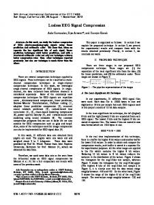
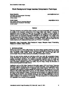
Giridhar Mandyam1 Mingui Sun2 Wes McCoy3 1 Department of Electrical and Computer Engineering The University of New Mexico Albuquerque, NM 87131 2 School of Medicine, The University of Pittsburgh 3550 Terrace Street Pittsburgh, PA 15261 3 Motorola Incorporated 5401 North Beach Street Fort Worth, TX 76137 neously. As a result, a large amount of data is collected, ABSTRACT especially in the study of sleep which lasts as long as ten The lossless compression of electroencephalographic (EEG) hours. Storage and handling of such a large data set is very data is of great interest to the biomedical research commuexpensive and inconvenient. nity. In this paper, a two-stage technique of lossless comAlthough classical compression techniques are available, pression involving decorrelating the sample points of the they were mostly designed for compressing images and EEG signal and then entropy coding the resulting signal speech signals for e�cient transmission and storage, where is examined. Two alternatives are presented for performa slight loss of information may not pose a signi cant probing the rst task. Speci cally, the rst stage consists either lem. In the case of EEG, however, even a small discrepancy of a xed coe�cient lter or a recursive least squares latbetween the original and the recovered signals can be very tice lter. The second stage employs arithmetic coding to problematic. In the spectral analysis of EEG signals, for perform the task of entropy coding the data. In the decomexample, the low-amplitude, high-frequency components of pression stage, exact inverse lters are applied to achieve the signal can be easily altered by using lossy compression, lossless compression. Simulations demonstrate the feasibilleading to erroneous analysis results. Due to this reason, ity of this method for lossless EEG data compression. lossy compression techniques are not commonly used for EEG data. A typical EEG waveform is shown in Figure 1 and its 1. INTRODUCTION spectrum is displayed in Figure 2. One can see the domiThe compression of EEG data is of great interest to many nance of low-frequency components in the signal. The specin the biomedical community. The motivation for this is trum of EEG data typically has an exponentially decaying due to the large amounts of data involved in collecting EEG shape with a few peaks in the high (40-100 Hz.) frequency information; such amounts may prove to be di�cult to store region, depending upon the subjects state at the time of or transmit. Recently, there has been focus in the area of data acquisition. lossless compression, mainly due to the necessity for full recovery of the data for diagnostic and liability purposes. 2. LOSSLESS COMPRESSION Many kinds of waveform data such as EEG signals are This section presents a description of the two-stage lossless highly correlated. Therefore, most lossless compression compression algorithm applied to the problem of lossless methods follow a two-stage approach [1], the rst stage becompression of EEG data. Two options that can be used for ing a decorrelator and the second stage being an entropy the decorrelation (energy reduction) stage have been outcoder. It is very important to determine appropriate choices lined below, followed by a description of the entropy coder for each stage. used to generate the results presented in Section 3.. Both Electroencephalography (EEG) is a primary tool for evalof the decorrelation options described below have minimal uation of brain functions. The EEG measures the variacompression overheads, in that neither approach requires tion of scalp electrical potentials which originates from extransmission of lter coe�cients. Also, it is not necessary tremely large numbers of activated neurons located on the to block the data into xed size blocks as is required in some cortex and inside the brain. The EEG is obtained by a�xlossless compression schemes. ing an array of gold-plated disks electrodes (about 1 cm in diameter) to the scalp, and the potential di�erences (usually 2.1. Reversible Filter Design in the order of 10 to 100 millivolts) between the recording One method of decorrelation is to design lters that take and reference electrodes are recorded. The weak EEG sigadvantage of the frequency content of the signal in question. nal is then ltered and ampli ed for storage and analysis. For instance, EEG signals are rich in low-frequency compoThe recorded EEG usually consists multiple channels correnents, with relatively less energy in higher frequencies. A sponding to electrode positions in order to study the spatial method of decorrelation could involve simply passing the distribution of the signal. EEG signal through a high-pass lter. The resulting signal In the past, the EEG were stored in the form of hardwill have considerably less information, and therefore will copies produced by a plotting device called polygraph. Due be signi cantly more compressible [3]. to the advances in digital signal processing (DSP) technolThe general form for such a high-pass lter would look ogy, multichannel EEG signals are sampled at 100 Hz to like 1,000 Hz and stored as binary data les. The number of channels mentioned has also increased. Modern EEG equip1 + a1 z ?1 + a2 z ?2 + ��� + a z ? (1) H ( z ) = ment is capable of acquiring hundreds of channels simulta1 + b z ?1 + b z ?2 + ��� + b z ? N
1
2
M
N
M
In order to design such a lter, one must keep in mind that the lter must have real coe�cients and must be reversible. The rst condition requires the poles of the lter to be in complex-conjugate pairs; the second condition requires that the leading coe�cients of the numerator and denominator polynomials in (1) be unity [3].
2.2. Recursive Least-Squares Lattice Filter Design
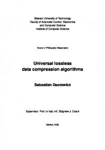
Another form of decorrelation involves the use of lattice lters. Among the various types of lattice lters, the recursive least-squares lattice lter (RLSL), shown in Figure 3, demonstrates quick convergence and is therefore e�ective as the decorrelation algorithm for lossless waveform compression [4]. The M th order forward and backward prediction error coe�cients, � (n) and (n) respectively, are given by the following equations. � (n) = � ?1 (n) + ? (n ? 1) ?1 (n ? 1)(2) (n) = ?1 (n ? 1) + ? (n ? 1)� ?1 (n) (3) n) (4) ? = ? B � ?(n1(? 1) ?1 ?1 (n) ? = ?� (5) F ?1(n) � ?1 (n) = �� ?1 (n ? 1) + (6)
?1 (n ? 1) ?1 (n ? 1)� ?1 (n) F ?1(n) = �F ?1 (n ? 1) + (7)
?1 (n ? 1)�2 ?1 (n) B ?1 (n) = �B ?1 (n ? 1) + ?1(n) 2 ?1 (n) (8)
2 ?1(n) 2 ?1 (n)
(n) = ?1 (n) ? (9) B ?1 (n) The parameter � is a xed constant arbitrarily close to, but not equaling 1. M
M
M
M
M
f;M
M
M
b;M
M
M
f;M
M
M
b;M
M
M
M
M
M
M
M
M
M
M
M
M
M
M
M
M
M
M
M
2.3. Arithmetic Coding
Arithmetic coding has been shown to give near optimal compression for white Gaussian residue sequences with dynamic ranges less than 14 bits [5]. At larger ranges, over ow may occur, and the running symbol table becomes large and cumbersome. Improvements have been made recently which solve this problem [6]. In principle, arithmetic coding is the mapping of a sequence of numbers or symbols onto a range of numbers between 0 and 1. The mapping takes into account a distribution function which can be xed or adaptive. It is possible, therefore, to implement an algorithm which is completely adaptive.
3. RESULTS
The data used to test the algorithms described in the preceding sections were obtained by recording spontaneous EEG (sampled at 256 Hz) from a sleep-deprived male subject using a 64-channel EEG ampli cation and acquisition system. Prior to digitization, a two-pole analog band-pass lter with cut-o� frequencies of 0.1 Hz and 70 Hz was used to pre- lter the data. Electrodes were placed at the sites de ned in the International 10-20 System [7] and at the mid-points between these standard electrode sites. When the subject reached Sleep Stage 2 [8], spindle signals were identi ed which were later segmented into separate les. Each le contains 64 channels of 4,608 samples. Four of these data sets were used to test the lossless compression algorithm. Results obtained for ve data channels have
been tabulated in Table 1. An RLSL lter was compared to two high pass FIR lters, given by [1 ? 4 7 ? 7 4 ? 1] and [1 ? 1]. The error residuals were encoded using the arithmetic coder proposed in [6]. The RLSL used utilized ten stages and a value for � of .99. Of the two FIR lters, the 6-weight lter provided very little reduction in variance because of a high gain factor, and therefore the results are not reported; only the results for the lter given by [1 ? 1] are reported. The results are reported in Table 1 for compression ratios calculated with respect to 16 bit quantization of the original data. Due to the dominance of low-frequency information in the EEG data, the simple high-pass operation achieved compression results comparable to that obtained by employing the RLSL lter.
4. CONCLUSIONS AND FUTURE WORK
This paper has presented some preliminary results of applying a two-stage lossless data compression algorithm to EEG data. The results indicate that we can achieve lossless compression ratios approaching a factor of two, Our experience with processing the data indicates that by making the rst stage (decorrelation) of the algorithm more e�cient by making it more suited to the nature of EEG data, we should be able to further increase the compression ratio. Moreover, a more suitable choice of entropy coder would improve the compression ratios. Future work would also entail suitably modifying the decorrelation stage by exploiting the cross-correlation between simultaneously acquired EEG data channels.
REFERENCES
[1] Mandyam, Giridhar, Neeraj Magotra and Samuel D. Stearns. \Lossless Waveform Compression." to appear in The Industrial Electronics Handbook. CRC Press. [2] Stearns, Samuel D., Li-Zhe Tan and Neeraj Magotra. \Lossless Compression of Waveform Data for Ef cient Storage and Transmission." IEEE Transactions on Geoscience and Remote Sensing. Vol. 31. No. 3. pp. 645-654. May, 1993. [3] McCoy, J.W. Lossless Waveform Compression. Ph.D. Thesis. The University of New Mexico. 1995. [4] McCoy, J.W., Neeraj Magotra, and Samuel D. Stearns. \Lossless Predictive Coding." 37th IEEE Midwest Symposium on Circuits and Systems. Lafayette, LA. August, 1994. [5] Witten, Ian H., Radford M. Neal and John G. Cleary. \Arithmetic Coding for Data Compression." Communications of the ACM. Vol. 30. No. 6. pp. 520-540. June, 1987. [6] Stearns, Samuel D. \Arithmetic Coding in Lossless Waveform Compression." IEEE Transactions on Signal Processing. Vol. 43. No. 8. pp. 1874-1879. August, 1995. [7] Bronzino, J. D. (ed.), \Biomedical Engineering Handbook," CRC Press , Boca Raton, Fl. 1995. [8] Barlow, J. S., \Electroencephalogram, Its Patterns and Origins," MIT Press , Cambridge, MA, 1995.
η (n)
Σ
0
Figure 1. EEG Waveform
η (n) 1
.......
η (n)
Σ
M-1
Γ (n-1)
Γ (n-1)
Γ (n-1)
Γ (n-1)
b,1
η (n) M
b,M
ix(n)
f,1
-1
ψ(n) 0
z
f,M
Σ
....... ψ(n) 1
-1
ψ (n)
z
M-1
Figure 3. RLSL Filter
Figure 2. EEG Waveform Spectrum File Number 1 2 3 4 5
RLSL CR Hi-Pass CR 1.63 1.65 1.51 1.65 1.43 1.59 1.40 1.56 1.40 1.53
Table 1. Compression Results
Σ
ψ (n) M