Hindawi Publishing Corporation ISRN Biomedical Engineering Volume 2013, Article ID 832527, 6 pages http://dx.doi.org/10.1155/2013/832527
Research Article Lossless Medical Image Compression by Integer Wavelet and Predictive Coding T. G. Shirsat and V. K. Bairagi Electronics Engineering Department, SAE Kondhwa, Pune, India Correspondence should be addressed to T. G. Shirsat;
[email protected] Received 30 March 2013; Accepted 8 May 2013 Academic Editors: F. Boccafoschi and A. El-Baz Copyright © 2013 T. G. Shirsat and V. K. Bairagi. This is an open access article distributed under the Creative Commons Attribution License, which permits unrestricted use, distribution, and reproduction in any medium, provided the original work is properly cited. The future of healthcare delivery systems and telemedical applications will undergo a radical change due to the developments in wearable technologies, medical sensors, mobile computing, and communication techniques. When dealing with applications of collecting, sorting and transferring medical data from distant locations for performing remote medical collaborations and diagnosis we required to considered many parameters for telemedical application. E-health was born with the integration of networks and telecommunications. In recent years, healthcare systems rely on images acquired in two-dimensional domains in the case of still images or three-dimensional domains for volumetric video sequences and images. Images are acquired by many modalities including X-ray, magnetic resonance imaging, ultrasound, positron emission tomography, and computed axial tomography (Sapkal and Bairagi, 2011). Medical information is either in multidimensional or multiresolution form, which creates enormous amount of data. Retrieval, efficient storage, management, and transmission of these voluminous data are highly complex. One of the solutions to reduce this complex problem is to compress the medical data without any loss (i.e., lossless). Since the diagnostics capabilities are not compromised, this technique combines integer transforms and predictive coding to enhance the performance of lossless compression. The proposed techniques can be evaluated for performance using compression quality measures.
1. Introduction Applications involve image transmission within and among health care organizations using public networks. In addition to compressing the data, this requires handling of security issues when dealing with sensitive medical information system. Compressing medical data includes high compression ratio and the ability to decode the compressed data at various resolutions. In order to provide a reliable and efficient means for storing and managing medical data computer-based archiving systems such as Picture Archiving and Communication Systems (PACSs) and Digital Imaging and Communications in Medicine (DICOM), standards were developed with the explosion in the number of images acquired for diagnostic purposes; the importance of compression has become invaluable in developing standards for maintaining and protecting medical images and health records. Compression offers a means to reduce the cost of storage and to increase the speed of transmission. Thus, medical images have attained a lot of
attention towards compression. These images are very large in size and require a lot of storage space. Image compression, can be lossless and lossy. In lossless compression, the recovered data is identical to the original, whereas in the case of lossy compression the recovered data is a close replica of the original with minimal loss of data [1–3]. The most common lossless compression algorithms are run-length encoding, LZW, DEFLATE, JPEG, JPEG 2000, JPEG-LS, LOCO-I, and so forth. Lempel-Ziv-Welch is a lossless data compression [4, 5].
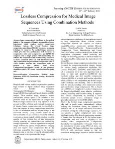
2. System Overview 2.1. IWT Followed by Predictive Coding. Figure 1 shows that the integer wavelet transform method is applied on the image 𝐹(𝑎) which divides the image into four subbands ss, sd, ds, and dd. Now predictive coding is applied on the four different bands separately giving outputs 𝐷1, 𝐷2, 𝐷3, and 𝐷4. The reconstruction process involves applying the predictive decoding followed by inverse integer transform to 𝑓10,
2
ISRN Biomedical Engineering [ss sd ds dd]
X
Predictive encoder
Integer wavelet transform
Predictive decoder
Inverse integer wavelet transform
[D1 D2 D3 D4]
F(a)
Approximation Sj−1
Evenj−1
Input Sj
+
Split
Oddj−1
Predict −
Update
Details Dj−1
Figure 2: Forward lifting scheme [10].
[f10 f11 f12 f13]
Figure 1: IWT followed by predictive coding.
𝑓11, 𝑓12, and 𝑓13 decoded bands. The reconstructed image is represented by “𝑋.” To verify the perfect reconstruction, the original and the reconstructed images are subtracted and the output is a dark image with maximum values as zero. In this first technique, IWT is performed first (Figure 1) followed by predictive coding technique on the transformed image, while in the second technique method, the predictive coding technique is applied first followed by the integer wavelet transform [6]. These methods use Haar filter in the lifting scheme and the filter coefficients which are given by Type I as follows: ℎ1 =
[−1 9 9 1] , (16)
[0 0 1 1] , ℎ2 = (−4)
(1)
where ℎ1 is the prediction filter coefficient and ℎ2 is the update filter coefficient in the lifting scheme. The filter coefficients of reduction are given by Type-II ℎ1 =
[−1 9 9 1] , (16 ∗ 1.5)
[0 0 1 1] . ℎ2 = (−4 ∗ 1.5)
(2)
The implementation can be done by using other filters in the lifting scheme [7].
3. Overview of Approach
𝐷𝑗−1 = Odd𝑗−1 − 𝑃 (even𝑗−1 ) , 𝑆𝑗−1 = Even𝑗−1 + 𝑈 (𝑑𝑗−1 ) .
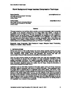
3.2. Forward Lifting Scheme. In this technique, the input signal is first split into even and odd indexed samples (Figure 2) as follows: (3)
(4)
Finally, the odd elements are replaced by the difference and the even elements by the averages. The lifting scheme provides integer coefficients, and so it is exactly reversible. Computations in the lifting scheme are done to saves a lot of memory and computation time. The total number of coefficients before and after the transform remains the same. 3.3. Reverse Lifting Scheme. Figure 3 shows that the inverse transform gets back the original signal by exactly reversing the operations of the forward transform with a merge operation in place of a split operation. Here, the number of the input signal must be a power of two, and these samples are reduced by half in each succeeding step until the last step which produces one sample. Reverse lifting scheme (Figure 3) is exactly reverse process of encoding which is exactly reversing the operations of the forward transform with a merge operation in place of a split operation as follows: Even𝑗−1 = 𝑠𝑗−1 − 𝑈 (𝑑𝑗−1 ) , Odd𝑗−1 = 𝑑𝑗−1 + 𝑃 (Even𝑗−1 ) ,
3.1. Implementation of IWT (Lifting Scheme). In integer wavelet transform, there is a mapping between integers to integers. The simplest lifting scheme is the lazy wavelet transform [8, 9].
(Odd𝑗−1 , even𝑗−1 ) = split (𝑠𝑗 ) .
The samples are correlated, so it is possible to predict odd samples from even samples which in the case of Haar transform are even values themselves. The difference between the actual samples, odd samples, and the prediction becomes the wavelet coefficients which is called lifting scheme. The update step follows the prediction step, where the even values are updated from the input even samples and the updated odd samples. Now this becomes the scaling coefficients, which will be passed on to the next stage of transform. The second lifting step is as follows:
(5)
𝑆𝑗 = merge (even𝑗−1 , Odd𝑗−1 ) . The Haar wavelet transform uses predict and update operations of order one. Using different predict and update operations of higher order, other wavelet transforms can be built using the lifting scheme [10–12]. Basic steps involved in the decomposition are firstly, the image/signal is sent through a low pass filter and band-pass filter simultaneously (predict and update in case of lifting) and then downsampled by a factor of 2.
ISRN Biomedical Engineering Approximation Sj−1
3 Evenj−1
− Update
Predict
Merge
LH
HL
HH
Output Original
Details Dj−1
LL F(x, y)
+
Transformed
Figure 4: Decomposition.
Oddj−1
Figure 3: Reverse lifting scheme [10]. +
f(n)
This process is repeated, and the final four outputs are combined to form the transformed image. The image is transformed in different subbands of which the first subband is called LL (which represents the low resolution version of the image), the second subband is called LH (which represents the horizontal fluctuations), the third band is called the HL (which represents the vertical fluctuations), and the fourth subband is called the HH (which represents the diagonal fluctuations) (Figure 4) [10]. The same procedure can be followed to obtain different levels of image decomposition, where we need the inputs given to the lifting or implementing with filter bank techniques. 3.4. Predictive Coding-Based Image Compression. There is no particular condition for invertible filters for prediction but broad statements can be made about sufficient conditions for lossless filtering. The condition as given in [8] says “The digital implementation of a filter is lossless if the output is the result of a digital one-to-one operation on the current sample and the recovery processor is able to construct the inverse operator.” It is important to note that the operations must be one-to-one not only on paper but also on the computer. Integer addition of the current sample and a constant is oneto-one under some amplitude constraints on all computer architectures [7]. Integer addition can be expressed as 𝑒 (𝑛) = 𝑓of (𝑥 (𝑛) + 𝑠 (𝑛)) ,
(6)
where 𝑓of is the overflow operator, 𝑥(𝑛) is the current sample, 𝑠(𝑛) an integer value which defines the transformation at time 𝑛, and 𝑒(𝑛) is the current filter output. The reverse operation is given by the following equation: 𝑥 (𝑛) = 𝑓of (𝑒 (𝑛) − 𝑠 (𝑛)) .
(7)
This process always leads to an increase in the number of bits required. To overcome this, rounding operation on the predictor output is performed making the predictor lossless. The lossless predictive encoder and decoder are shown in Figures 5 and 6. Generally, the second-order predictor is used which is also called finite impulse response (FIR) filter. The simplest predictor is the previous value; in this experiment, the predicted value is the sum of the previous two values with alpha and beta being the predictor coefficients, 𝑓∧ (𝑛) = ⟨𝑓 (𝑛 − 1)⟩ .
(8)
Predictor
Rounding
Entropy coder
f∧
Figure 5: Predictive encoder [5].
In the process of predictive coding, input image is passed through a predictor where it is predicted with its two previous values, 𝑓∧ (𝑛) = 𝛼 ∗ 𝑓 (𝑛 − 1) + 𝛽 ∗ 𝑓 (𝑛 − 2) ,
(9)
where 𝑓∧ (𝑛) is the rounded output of the predictor, 𝑓(𝑛 − 1) and 𝑓(𝑛 − 2) are the previous values, and 𝛼 and 𝛽 are the coefficients of the second-order predictor ranging from 0 to 1. The output of the predictor is rounded and is subtracted from the original input. This difference is given by 𝑑 (𝑛) = 𝑓 (𝑛) − 𝑓∧ (𝑛) .
(10)
Now this difference is given as an input to the decoder part, of the predictive coding technique. In the decoding part the difference is added with the 𝑓∧ (𝑛) to give the original data as follows: 𝑓 (𝑛) = 𝑑 (𝑛) + 𝑓∧ (𝑛) .
(11)
Algorithm (1) Read the original image. (2) Get size of image in 𝑀 × 𝑁. (3) Get a new matrix with first two columns and rows with zeros padded to the original matrix. (4) Multiply 𝑁th and 𝑁 + 1th element in row with alpha and beta, respectively. After rounding it off, add those predicted values with their original values. (5) Repeat steps (3) and (4) for 𝑀 × 𝑁 iterations. Haar wavelet transformation is used in lifting scheme to perform the operation of averaging and differencing to arrive at a new matrix representing the same image in a more concise manner as averaging: (64+2)/2 = 33, (3+61)/2 = 32, (60+6)/2 = 33, (7 + 57)/2 = 32, differencing: 64 − 33 = 31, 3 − 32 = −29, 60 − 33 = 27 and 7 − 32 = −25.
4
ISRN Biomedical Engineering
Entropy decoder
Predictive-based coding methods
+
f∧
Table 1: Comparison of available techniques.
f(n)
d(n)
Predictor
Rounding
LJPEG
Figure 6: Predictive decoder [5]. JPEG LS
2D array representing the 8 × 8 image [13]: 64 9 17 ( (40 (32 ( 41 49 (8
2 55 47 26 34 23 15 58
3 54 46 27 35 22 14 59
61 12 20 37 29 44 52 5
60 13 21 36 28 45 53 4
6 51 43 30 38 19 11 62
7 50 42 31 39 18 10 63
57 16 24 ) 33) . 25) ) 48 56 1)
(12) JPEG 2000
Transformed array after operation on each row of 8 × 8 image [13]: 32.5 32.5 32.5 ( (32.5 (32.5 ( 32.5 32.5 (32.5
0 0 0 0 0 0 0 0
0.5 −0.5 −0.5 0.5 0.5 −0.5 −0.5 0.5
0.5 −0.5 −0.5 0.5 0.5 −0.5 −0.5 0.5
31 −23 −15 7 −1 9 17 −25
−29 21 13 −5 3 −11 −19 27
27 −19 −11 3 −5 13 21 −29
−25 17 9 ) −1 ) . 7 ) ) −15 −23 31 )
(13)
MED
Final transformed matrix after one step [13]: 32.5 0 0 ( ( 0 ( 0 ( 0 0 ( 0
0 0 0 0 0 0 0 0 0 0 0 0 0 0.5 0.5 0 −0.5 −0.5 0 0.5 0.5 0 −0.5 −0.5
0 0 4 4 27 −11 −5 21
0 0 −4 −4 −25 9 7 −23
0 0 4 4 23 −7 −9 25
0 0 −4 ) −4 ) . −21) ) 5 11 −27)
GAP
(14)
3.5. Predictive Coding Techniques. Various predictive-based coding techniques are analyzed for their effectiveness as in Table 1. 3.6. Comparative Analysis. Predictor is the first and the most important step which removes a large amount of spatial redundancy. The most representative predictors are median edge detection (MED) predictor used in JPEG-LS standard and gradient adjusted predictor (GAP) used in CALIC. But novel threshold controlled required, gradient edge detection (GED) predictor which combines simplicity of MED and efficiency of GAP. Analysis shows that GED gives comparable entropies with much complicated GAP. Hence, the suggested method provides efficient way by reducing complexity for Xray, CT, and MRI images.
GED
CALIC
Blending predictor (model based)
Comments (1) Predictive algorithm used (2) Huffman or arithmetic entropy algorithm (3) Highest compression ratio (1)Nearly lossless (2) High speed and compression ratio, mostly used (3) JPEG-LS algorithm is more scalable than JPEG and JPEG 2000 (1) Wavelet-based method (2) High noise compensation ratio (3) JPEG 2000 delivers a typical compression gain in the range of 20%, depending on the image characteristics (4) Higher-resolution images tend to benefit more, where JPEG-2000’s spatial-redundancy prediction can contribute more to the compression process (5) JPEG 2000 has quality advantage over JPEG (1) Belongs to the group of switching predictors (2) MMSE performs the adaptation prediction coefficient on the basis of a training set of causal pixels this approach can achieve better results (3) Redundancy between frames is reduced by the prediction of each pixel based (1) Gradient estimation around the current pixel (2) Gradient estimation is estimated by the context of current pixel (1) GED predictor is a simple combination of gradient and median predictors (2) Pixel in context of horizontal edge, vertical edge or smooth region (1) Poor performance (2) High-compression ratio (3) More complex algorithm with more resources (1) Models for particular pixel designed by combination of linear subpredictors (2) Bayesian model averaging used (BMA), risk associated with this model (3) Better performance
[13–15].
Lossless image compression has to preserve the exact value of each pixel, regardless of whether there is noise or not. Measure performance predictor can be expressed over the degree of compression. Predictor only eliminates redundancy, and, in fact, does not do compression. Linear predictor is easy and efficient method among this for medical image.
ISRN Biomedical Engineering
5 Table 2: Compression ratio of Type I scheme.
Serial number
Name of image
1
Ulsar
2
Skull
3
MRI
4
Infrared
5
Boat
6
Ulsar infrared
Format bmp jpg bmp jpg bmp jpg bmp jpg bmp jpg bmp jpg
Original size 263 kb 54.1 kb 516 kb 27.5 kb 168 kb 10.2 kb 3 mb 596 kb 768 kb 83.6 kb 263 kb 20 kb
Encoded size 175 kb 13.2 kb 289 kb 13.9 kb 129 kb 9.56 kb 395 kb 59.8 kb 395 kb 39.8 kb 175 kb 9.28 kb
Compression ratio 1 : 1.50 1 : 4.00 1 : 1.78 1 : 1.97 1 : 1.30 1 : 1.06 1 : 7.77 1 : 9.90 1 : 1.94 1 : 2.10 1.50 : 1 2.15 : 1
Encoded size 175 kb 13.2 kb 289 kb 13.9 kb 129 kb 9.56 kb 395 kb 59.8 kb 395 kb 39.8 kb 175 kb 9.28 kb
Compression ratio 1 : 1.50 1 : 4.00 1 : 1.78 1 : 1.97 1 : 1.30 1 : 1.06 1 : 7.77 1 : 9.90 1 : 1.94 1 : 2.10 1.50 : 1 2.15 : 1
Table 3: Compression ratio of Type II scheme. Serial number
Name of image
1
Ulsar
2
Skull
3
MRI
4
Infrared
5
Boat
6
Ulsar infrared
Format bmp jpg bmp jpg bmp jpg bmp jpg bmp jpg bmp jpg
Original size 263 kb 54.1 kb 516 kb 27.5 kb 168 kb 10.2 kb 3 mb 596 kb 768 kb 83.6 kb 263 kb 20 kb
4. Experimental Result
6. Future Scope
For more details, see Tables 2 and 3.
The lifting scheme used is only a two-level lifting scheme. In order to improve the entropy of the transformed image, a multilevel lifting scheme is to be implemented. The performance of the predictive coding can be increased by using higher order predictors with two-dimensional predictions. Another possibility for improving the performance would be to use model-based and adaptive approaches. The performance for lossless compression techniques can also be improved by performing different combinations of various transforms and coding techniques involving IWT and predictive coding, for example, IWT followed by predictive or predictive followed by IWT, and by realizing the most optimal combination that gives the least entropy.
5. Discussion With the previous available technique of compression, exact inverse is possible so as to recover the original image without any loss. However, due to the finite number representation of computers and rounding off the floating point numbers, exact lossless version of original image after reconstruction is not possible. IWT is the solution form, in which it is seen that using lifting scheme by the perfect reconstruction is possible. Also hardware Design of 2-D High Speed DWT by using Multiplier Wavelet Filters easier [16]. These methods for lossless medical image compression performing integer wavelet transform using lifting technique and then lossless predictive coding technique give efficient compression; different combinations of transformed and predicted images are inspected. IWT is giving the smallest file size with Haar wavelet. 𝛼 and 𝛽 are the coefficients of the second-order predictor ranging from 0 to 1, giving better result at values 0.5.
7. Conclusion Among various methods of wavelet transform, it is suggested that the predictive method gives more compression rather than plane wavelet-based compression. In lossless predictive coding technique, we take the difference or prediction error into consideration rather than taking into account the original sample or image; hence,
6 very little amount of data can be lost while predicting, but with acceptable limit of image quality. Entropy and scaled entropy are used to calculate the performance of the system for compressed images.
References [1] M. Das and N. K. Loh, “New studies on adaptive predictive coding of images using multiplicative autoregressive models,” IEEE Transactions of Image Processing, vol. 1, no. 1, pp. 106–111, 1992. [2] X. Wu and N. Memon, “Context-based, adaptive, lossless image coding,” IEEE Transactions on Communications, vol. 45, no. 4, pp. 437–444, 1997. [3] V. K. Bairagi and A. M. Sapkal, “ROI based DICOM image compression for telemedicine,” Sadhana, vol. 38, no. 1, pp. 123– 131, 2013. [4] V. K. Bairagi and A. M. Sapkal, “Automated region based hybrid compression for DICOM MRI images for telemedicine applications,” The IET Science, Measurement & Technology, vol. 6, no. 4, pp. 247–253, 2012. [5] N. Memon and X. Wu, “Recent developments in contextbased predictive techniques for lossless image compression,” Computer Journal, vol. 40, no. 2-3, pp. 127–135, 1997. [6] N. V. Boulgouris, D. Tzovaras, and M. G. Strintzis, “Lossless image compression based on optimal prediction, adaptive lifting, and conditional arithmetic coding,” IEEE Transactions on Image Processing, vol. 10, no. 1, pp. 1–14, 2001. [7] D. Neela, Lossless Medical Image Compression Using Integer Transforms and Predictive Coding Technique, Department of Electrical and Computer Engineering, Jawaharlal Nehru Technological University, Jawaharlal Nehru, India, 2010. [8] I. Daubechies and W. Sweldens, “Factoring wavelet transforms into lifting steps,” Journal of Fourier Analysis and Applications, vol. 4, no. 3, pp. 245–267, 1998. [9] J. W. McCoy, N. Magotra, and S. Stearns, “Lossless predictive coding,” in Proceedings of the 37th Midwest Symposium on Circuits and Systems, pp. 927–930, August 1994. [10] A. Vasuki and P. T. Vasanta, “Image compression using lifting and vector quantization,” GVIP Journal, vol. 7, no. 1, 2007. [11] A. Fukunaga and A. Stechert, “Evolving nonlinear predictive models for lossless image compression with genetic programming,” Jet Propulsion Laboratory California Institute of Technology 4800, Oak Grove Dr, 2000, M/S 126-347. [12] Simon Fraser University and B. C. Burnaby, “A two-stage algorithm for multiple description predictive coding,” in Canadian Conference on Electrical and Computer Engineering (CCECE ’08), pp. 6854–6887, May 2008. [13] K. H. Talukder and K. Harada, “Harr wavelet based approach for image compression and quality assessment of compressed image,” International Journal of Applied Mathematics, vol. 36, no. 1, 2010. [14] S. Arivazhagan, W. Sylvia Lilly Jebarani, and G. Kumaran, “Performance comparison of discrete wavelet transform and dual tree discrete wavelet transform for automatic airborne target detection,” in Proceedings of the International Conference on Computational Intelligence and Multimedia Applications (ICCIMA ’07), pp. 495–500, December 2007. [15] ISO/IEC/JTC1/SC29/WG1 N390R, JPEG, 2000 Image Coding System, March 1997, http://www.jpeg.org/public/wg1n505.pdf .
ISRN Biomedical Engineering [16] H. K. Bhaldar and V. K. Bairagi, “Hardware design of 2-D high speed DWT by using multiplierless 5/3 wavelet filters,” International Journal of Computer Applications, vol. 59, no. 17, pp. 42–46, 2012.
International Journal of
Rotating Machinery
The Scientific World Journal Hindawi Publishing Corporation http://www.hindawi.com
Volume 2014
Journal of
Robotics Hindawi Publishing Corporation http://www.hindawi.com
Volume 2014
Hindawi Publishing Corporation http://www.hindawi.com
Advances in
Mechanical Engineering
Journal of
Sensors Volume 2014
Hindawi Publishing Corporation http://www.hindawi.com
Volume 2014
Engineering
Hindawi Publishing Corporation http://www.hindawi.com
Volume 2014
Journal of
Hindawi Publishing Corporation http://www.hindawi.com
International Journal of
Chemical Engineering Hindawi Publishing Corporation http://www.hindawi.com
Volume 2014
Volume 2014
Submit your manuscripts at http://www.hindawi.com International Journal of
Distributed Sensor Networks Hindawi Publishing Corporation http://www.hindawi.com
Advances in
Civil Engineering Hindawi Publishing Corporation http://www.hindawi.com
Volume 2014
Volume 2014
VLSI Design Advances in OptoElectronics
Modelling & Simulation in Engineering
International Journal of
Navigation and Observation Hindawi Publishing Corporation http://www.hindawi.com
Volume 2014
Hindawi Publishing Corporation http://www.hindawi.com
Hindawi Publishing Corporation http://www.hindawi.com
Volume 2014
Hindawi Publishing Corporation http://www.hindawi.com
Advances in
Acoustics and Vibration Volume 2014
Hindawi Publishing Corporation http://www.hindawi.com
Volume 2014
Volume 2014
Journal of
Control Science and Engineering
Active and Passive Electronic Components Hindawi Publishing Corporation http://www.hindawi.com
Volume 2014
International Journal of
Journal of
Antennas and Propagation Hindawi Publishing Corporation http://www.hindawi.com
Shock and Vibration Volume 2014
Hindawi Publishing Corporation http://www.hindawi.com
Volume 2014
Hindawi Publishing Corporation http://www.hindawi.com
Volume 2014
Electrical and Computer Engineering Hindawi Publishing Corporation http://www.hindawi.com
Volume 2014