nentiation transforms the CPM signal with modulation index h < 1/2 into a CPM signal with .... pulse amplitude modulation (PAM) signals x(t, a) = â i. Kâ1. â k=0.
1
Low-Complexity Generic Receiver for Burst-Mode Continuous Phase Modulation Vincent Le Nir, and Bart Scheers
Abstract—This paper describes a low-complexity generic receiver for burst-mode continuous phase modulation. The burst consists of a continuous wave (CW) signal followed by a pseudorandom sequence and a data sequence modulated by continuous phase modulation (CPM). Joint coarse carrier frequency, phase and time synchronization is performed on the CW signal. Fine time synchronization is performed on the pseudo-random sequence part of the CPM signal. Fine carrier frequency and phase synchronization is performed on the CPM signal. Exponentiation transforms the CPM signal with modulation index h < 1/2 into a CPM signal with modulation index h = 1/2. Linear demodulation filters the synchronized signal with the first pulse of Laurent’s linear representation of CPM signals. Decision logic is applied to the filtered signal to recover the data sequence. Simulations are conducted to show the influence of the CPM parameters (modulation index, pulse length, shaping pulse, differential encoder) and the burst parameters (length of the CW signal, length of the CPM pseudo-random sequence, length of the CPM data sequence) on the different algorithms.
•
•
Index Terms—Continuous Phase Modulation, Low-Complexity Receiver, Burst-Mode.
I. I NTRODUCTION ONTINUOUS phase modulation (CPM) has the advantages of high spectral efficiency due to the phase continuity and high power efficiency due to the constant envelope. However, CPM has the disadvantage of the high implementation complexity required to build an optimal receiver [1]. CPM has been used in several well-known communications protocols such as GSM and Bluetooth. CPM is also envisioned for the NATO narrow band waveform (NBWF) [2]. This paper describes a low-complexity generic receiver for burst-mode continuous phase modulation. The receiver works for full response CPM (pulse length L = 1) as well as partial response CPM (L > 1) for any modulation index (h 6 1/2). The burst consists of a continuous wave (CW) signal followed by a pseudo-random sequence and a data sequence modulated by CPM. The low-complexity generic receiver can be split into the following tasks : • Joint coarse carrier frequency, phase and time synchronization is performed on the CW signal. The synchronization algorithm is an extension of the iterative frequency estimation algorithm by interpolation on Fourier coefficients described in [3] to take into account carrier phase and time synchronization. The synchronization algorithm searches for the time offset whose estimated iterative frequency offset has the maximum power and
C
V. Le Nir and B. Scheers are with the Department Communication, Information, Systems & Sensors (CISS), Royal Military Academy, Brussels, BELGIUM e-mail: {vincent.lenir,bart.scheers}@rma.ac.be Manuscript received February 01, 2016.
•
•
•
determines the phase offset of the CW signal at the time and frequency offset estimates. Fine time synchronization is performed on the pseudorandom sequence part of the CPM signal as described in [4]. A peak search of the correlation function between the received signal and a stored CPM pseudo-random sequence around the estimated coarse time offset is performed. Fine carrier frequency and phase synchronization is performed on the CPM signal. Two fine carrier frequency and phase synchronization algorithms are studied in this paper. The first algorithm is a data aided (DA) carrier frequency and phase synchronization algorithm applied to the CPM pseudo-random sequence signal. The second algorithm is a non data aided (NDA) carrier frequency and phase synchronization algorithm applied to the full CPM signal. The second algorithm is an extension of the NDA feed forward carrier frequency synchronization algorithm with minimum shift keying (MSK)-type signals as described in [5]. The extended algorithm downsamples the signal at the symbol rate, transforms the resulting signal into a CPM signal with four constellation points, takes the fourth power of the transformed signal, and applies the iterative frequency estimation algorithm [3] on the fourth powered signal at the time offset estimate. Exponentiation transforms the CPM signal with modulation index h < 1/2 into a CPM signal with modulation index h = 1/2. An implementation of the transformation of a CPM signal with small modulation index into a CPM signal with modulation index h = 1/2 is described in [6]. Linear demodulation filters the synchronized signal with the first pulse of Laurent’s linear representation of CPM signals [7], [8]. The linear demodulator has the advantage of a good trade off between performance and complexity compared to maximum-likelihood receivers implemented using Viterbi or iterative algorithms [9], [10], [11], [12]. Decision logic is applied to the filtered signal to recover the data sequence. The decision logic algorithm performs a differential detection using the real and imaginary samples. If the CPM modulator is preceded with a differential encoder, the inherent performance loss due to the differential detection can be avoided and the overall performance can be improved [13].
The paper is organized as follows. In section II, we present the signal model. More specifically, the complex baseband representation of a CPM signal and the burst-mode transmission model are presented. In section III, the different algorithms of the low-complexity receiver are described. These are the
2
joint coarse carrier frequency, phase and time synchronization algorithm, the fine time synchronization algorithm, the fine carrier frequency and phase synchronization algorithm, the exponentiation algorithm, the linear demodulation algorithm and the decision logic algorithm. In Section IV, simulations are conducted to show the influence of the burst parameters (length of the CW signal, length of the CPM pseudo-random sequence, length of the CPM data sequence) and CPM parameters (modulation index, pulse length, shaping pulse, differential encoder) on the different algorithms. Finally, section V concludes the paper.
� sin πhq(t) sin(πh) �� sin πh 1 − q(t − LT ) p(t) = sin(πh) 0
y(t, a)
P i
i
with h the modulation index, T the symbol period, a = {ai } the information belonging to the binary alphabet {±1}, q(t) �t the phase response of the system with q(t) = 0 g(u)du and satisfying the condition q(LT ) = 1, L the pulse length, g(t) the shaping pulse time-limited to the interval [0, LT] and satisfying the condition g(t) = g(LT − t). Full response CPM corresponds to L = 1. Partial response CPM corresponds to L > 1. MSK-type modulation corresponds to a binary CPM with h = 1/2. The most important shaping pulses are the rectangular (LREC), raised-cosine (LRC), spectral raised cosine (LSRC), Gaussian and tamed FM as defined in [1].
(7)
otherwise
= Ae j (2παt+φ) x(t − τ, a) + n(t) ≈A
The complex baseband representation of a CPM signal is given by x(t, a) = e jψ (t,a) (1) X ψ(t, a) = πh ai q(t − iT ) (2)
LT ≤ t ≤ 2LT
Assuming transmission over an additive white Gaussian noise (AWGN) channel, the complex baseband representation of the received signal can be written as
II. S IGNAL M ODEL A. Representation of a CPM signal
0 ≤ t ≤ LT
b0, i−1 e j (πha i +2παt+φ) c0 (t − τ − iT ) + n(t)
(8) with A the received signal amplitude, α the carrier frequency offset, φ the carrier phase offset, τ the time offset and n(t) the AWGN with variance N0 /2 per dimension. The received samples can be written as (9) y(k) = y(t, a) t= kT F with F the oversampling factor. C. Burst-mode transmission model The burst-mode transmission model considers the transmission of independent bursts. Each burst has a known duration and structure as described in [4] and shown in Figure 1.
CW
CPM Pseudo-Random Sequence
Ncw
Nprs
CPM Data Sequence Nds Ntot
Fig. 1. Structure of the burst
B. Laurent’s representation of a CPM signal Laurent [7] showed that the complex baseband representation of a CPM signal (1) can be written as a sum of K = 2 L−1 pulse amplitude modulation (PAM) signals x(t, a) =
−1 X KX i
bk, i ck (t − iT )
(3)
k=0
with bk,i a function of the information sequence {ai } and ck (t) an equivalent shaping pulse of the k th PAM signal [8]. Laurent also showed that c0 (t), which represents the pulse of longest duration (L +1)T, also happens to have the highest energy and is the most important component of the signal [7]. Therefore, the baseband signal (1) can be approximated as x(t, a) ≈
X
b0, i c0 (t − iT )
(4)
i
b0, i = b0, i−1 e jπha i
(5)
The burst of length Nt ot consists of a continuous wave (CW) signal of length Ncw , a CPM pseudo-random sequence signal of length N pr s and a CPM data sequence signal of length Nds . Such burst structure has already been adopted in [4], in which the authors exploit the CW signal for carrier frequency and phase synchronization and the CPM pseudorandom sequence signal for time synchronization. However, the accuracy of the carrier frequency and phase estimates might not be enough for short CW signal length, non-smooth shaping pulse g(t) and/or long pulse duration L. In this paper, two fine carrier frequency and phase synchronization algorithms are studied. The first algorithm is a DA carrier frequency and phase synchronization algorithm applied to the CPM pseudo-random sequence signal. The second algorithm is a NDA carrier frequency and phase synchronization algorithm applied to the full CPM signal. These algorithms allow to obtain more efficient carrier frequency and phase synchronization accuracy if necessary. III. L OW-C OMPLEXITY R ECEIVER
c0 (t) =
L−1 Y l=0
p(t + lT )
(6)
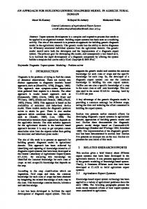
The low-complexity generic receiver depicted in Figure 2 is described in the following paragraphs.
3
τˆ
y(k)
FINE TIME SYNCHRONIZATION
×
× ˆ
ˆ φ) e−j(2παt+
COARSE FREQUENCY PHASE TIME SYNCHRONIZATION
TRANSFORMATION INTO h = 1/2
LINEAR DEMODULATION c0 (−k)
ˆ
ˆ φ) e−j(2παt+
Sample at iT + τˆ
DECISION LOGIC
a ˆi
FINE FREQUENCY PHASE SYNCHRONIZATION
Fig. 2. Block diagram of the low-complexity receiver
A. Joint coarse carrier frequency, phase and time synchronization Joint coarse carrier frequency, phase and time synchronization is performed on the CW signal. The synchronization algorithm is an extension of the iterative frequency estimation algorithm by interpolation on Fourier coefficients described in [3] to take into account carrier phase and time synchronization. Let Nc w the number of samples of the CW signal, Nt ot the total number of samples of the burst, αˆ the estimated carrier frequency offset with βˆ the integer part of the estimated carrier frequency offset and δˆ the non-integer part of the estimated frequency offset. The extended algorithm is described in Algorithm 1 with N = Nc w . Algorithm 1 Joint coarse carrier frequency, phase and time synchronization algorithm 1 Loop : for all k, yk = [y(k) . . . y(k + N )] 2 Let Yk = FFT (yk ), Ek (i) = |Yk (i)| 2 , i = 0 . . . N − 1 3 Find βˆ = argmax Ek (i) i
4 5 6 5 7
8 9
Set δˆ0 = 0 Loop : for each i from 1 to Q ˆ δˆ NP −1 β+ i−1 +p Xp = y(n)e− j2πn N , p = ±0.5 n=0 ( ) 0.5 +X −0.5 δˆi = δˆi−1 + 21 Re X X 0.5 −X −0.5 ˆ δˆ β+ NP −1 Q X0, k = y(n)e− j2πn N n=0 ˆ δˆQ β+ N
αˆ k = Coarse time offset estimate : τˆ = argmax |X0, k | 2 k
Coarse carrier frequency offset estimate : αˆ = ατˆ 11 Coarse carrier phase offset estimate : φˆ = arg(X0, τˆ ) 10
This algorithm searches for the time offset whose estimated iterative frequency offset has the maximum power. The carrier frequency offset estimate is the carrier frequency offset at the time offset estimate. The carrier phase offset estimate is the carrier phase offset of the CW signal at the time and frequency offset estimates.
B. Fine time synchronization Fine time synchronization is performed on the addition of the CW signal and the CPM pseudo-random sequence signal. A peak search of the correlation function between the received signal and a stored CW signal plus CPM pseudo-random sequence signal around the estimated coarse time offset is performed. Assuming N = Ncw + N pr s , the optimization problem can be written as τˆ = argmax |r (k)| 2
(10)
k
with r (k) =
N −1 1 X y(n + k)x ∗ (n) N n=0
k ∈ [τˆ −
Ncw Ncw . . . τˆ + ] 2 2 (11)
C. Fine carrier frequency and phase synchronization Fine carrier frequency and phase synchronization is performed on the CPM signal. Two fine carrier frequency and phase synchronization algorithms are studied in this paper. The first algorithm is a DA carrier frequency and phase synchronization algorithm applied to the CPM pseudo-random sequence signal. The second algorithm is a NDA carrier frequency and phase synchronization algorithm applied to the full CPM signal. 1) Data aided fine carrier frequency and phase synchronization: This algorithm applies the iterative frequency estimation algorithm by interpolation on Fourier coefficients described in [3] to the correlation function between the received signal and a stored CPM pseudo-random sequence signal at the time offset estimate. The algorithm is described in Algorithm 2 with N = N pr s and z = [z(0) . . . z(N − 1) with z(k) = y(k)x ∗ (k + τ) ˆ
(12)
Finally, the DA carrier frequency estimate is given by αˆ = ˆ δˆQ β+ ˆ N , and the DA carrier phase estimate by φ = arg(X0 ). 2) Non data aided fine carrier frequency and phase synchronization: The second algorithm is an extension of the NDA feed forward carrier frequency synchronization algorithm with MSK-type signals as described in [5]. We assume that the received signal is low-pass filtered to eliminate outof-band noise and sampled at symbol rate 1/T. The extended
4
algorithm uses exponentiation to transform the CPM signal with modulation index h < 1/2 into a CPM signal with modulation index h = 1/2. An implementation of the transformation of a CPM signal with small modulation index into a CPM signal with modulation index h = 1/2 is described in [6]. Exponentiation can also be described by the following method arg(y(k)) 1 ˜ ψ(k) = h 2
(13)
The received signal is then reconstructed by the following formula ˜ y˜ (k) = e jψ (k ) (14) The reconstructed signal is a CPM signal with four constellation points for any shaping pulse whenever the pulse length L = 1, 2. For L ≥ 3, an additional exponentiation taking into account the pulse length L and the shaping pulse might be necessary to obtain a CPM signal with four constellation points. In [5], a quadratic non linearity (QNL) is applied on the received signal z(k) = (−1) k y˜ (k) 2 for CPM signals without inter symbol interference (ISI) or pulse length L = 1. However, this QNL does not apply for partial response CPM with ISI (L > 1). After the transformation of the received signal into a CPM signal with four constellation points by exponentiation, we propose to take the fourth power of the transformed signal z(k) = y˜ (i) 4 for L > 1, and to apply the iterative frequency estimation algorithm [3] on the resulting signal. The algorithm can also be described in Algorithm 2 with N = N pr s + Nds and z = [z(0) . . . z(N − 1)]. Algorithm 2 Iterative frequency estimation algorithm for DA and NDA carrier frequency and phase synchronization algorithms 2 3
Let Z = FFT (z), E(k) = | Z (k)| 2 , k = 0 . . . N − 1 Find βˆ = argmax E(k)
four constellation points while keeping the initial phase offset. The transformation is described by the following method arg(y(k)) 1 1 π ˜ ψ(k) = + ( − 2) (15) h 2 h 8 for even 1/h numbers. For odd 1/h numbers, an additional phase unwrapping is necessary Algorithm 3 Phase unwrapping for odd 1/h numbers 1 Loop : for all k ˜ ˜ − 1) > 2π 2 if ψ(k) − ψ(k ˜ ˜ 3 ψ(k) = ψ(k) −π ˜ ˜ − 1) < 2π 4 if ψ(k) − ψ(k ˜ ˜ 5 ψ(k) = ψ(k) +π The received signal is then reconstructed by the following formula ˜ y˜ (k) = e jψ (k ) (16) Similarly to the NDA fine carrier frequency and phase synchronization algorithm, the reconstructed signal is a CPM signal with four constellation points for any shaping pulse whenever the pulse length L = 1, 2. For L ≥ 3, an additional exponentiation taking into account the pulse length L and the shaping pulse might be necessary to obtain a CPM signal with four constellation points. E. Linear demodulation Linear demodulation filters the synchronized signal with the first pulse of Laurent’s linear representation of CPM signals. The linear demodulator has the advantage of a good trade off between performance and complexity compared to maximumlikelihood receivers implemented using Viterbi or iterative algorithms [9], [10], [11], [12]. The convolution and sampling operation can be written as
k
4 5 6 5 7
Set δˆ0 = 0 Loop : for each i from 1 to Q ˆ δˆ NP −1 β+ i−1 +p Xp = z(n)e− j2πn N , p = ±0.5 n=0 ( ) 0.5 +X −0.5 δˆi = δˆi−1 + 12 Re X X 0.5 −X −0.5 ˆ δˆ β+ NP −1 Q X0 = z(n)e− j2πn N n=0
Finally, the NDA carrier frequency estimate is given by ˆ δˆ β+ αˆ = N Q h4 , and the NDA carrier phase estimate by φˆ = arg(X0 ) h4 . With the QNL (L = 1), the NDA carrier frequency ˆ δˆ β+
Q h estimate is given by αˆ = N 2 , and the NDA carrier phase estimate by φˆ = arg(X0 ) h2 . For L ≥ 3, a further exponentiation of L th power is applied on equation (13) and a division by L is necessary on the NDA carrier frequency and phase estimates.
D. Transformation into a CPM signal with h = 1/2 The CPM signal with modulation index h < 1/2 is transformed into a CPM signal with modulation index h = 1/2 with
s(i) = (y ∗ c0 )(k) | i=F k+τˆ
(17)
F. Decision Logic Decision logic is applied to the filtered signal to recover the data sequence. The decision logic algorithm performs a differential detection using the real and imaginary samples. ( Im(s(i))Re(s(i − 1)) i even aˆ i = (18) −Re(s(i))Im(s(i − 1)) i odd If the CPM modulator is preceded with a differential encoder, the inherent performance loss due to the differential detection can be avoided and the overall performance can be improved [13]. aˆ i = Re((− j) i s(i))
(19)
IV. S IMULATION R ESULTS Simulations are conducted to show the influence of the CPM parameters (modulation index, pulse length, shaping pulse, differential encoder) and the burst parameters (length of the CW signal, length of the CPM pseudo-random sequence, length of the CPM data sequence) on the different algorithms.
5
0
0
10
10
−1
−1
10
BER
BER
10
−2
10
−3
10
−4
10
0
1−REC h=1/2 2−REC h=1/2 1−REC h=1/4 2−REC h=1/4 1−REC h=1/6 2−REC h=1/6 1−REC h=1/8 2−REC h=1/8 2
4
−2
10
−3
10
−4
6
8
10 12 Eb/N0 (dB)
14
16
18
10
20
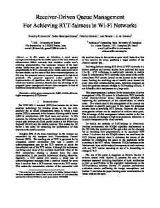
Fig. 3. Influence of the modulation index
0
2
4
6
8 Eb/N0 (dB)
10
12
14
16
Fig. 4. Influence of the pulse length and the shaping pulse
A. Influence of the modulation index
0
10
−1
10
BER
Figure 3 shows the BER performance of the low-complexity generic receiver with rectangular shaping pulse and pulse length L = 1 (1-REC) and L = 2 (2-REC) for different modulation indexes (h = 1/2, 1/4, 1/6, 1/8). The BER curves correspond to the genie aided curves which can be reached with adequate CW, CPM pseudo-random sequence, CPM data sequence signal lengths as will be discussed in the following paragraphs for the DA and NDA fine carrier frequency and phase synchronization algorithms. Simulations shows that the BER performance degrades as the modulation index decreases.
1−REC h=1/2 2−REC h=1/2 3−REC h=1/2 3−GAUSSIAN h=1/2
−2
10
−3
10
B. Influence of the pulse length and the shaping pulse Figure 4 shows the BER performance of the low-complexity generic receiver with modulation index h = 1/2 for different pulse length L = 1, 2, 3 and shaping pulses (REC, GAUSSIAN). Simulations shows that the BER performance degrades as the pulse length increases. The loss of BER performance for L = 2 compared to L = 1 is small (0.4 dB). The loss of BER performance is larger for L = 3. In fact, for L = 3, it can be shown that the energy contained in the Laurent’s second pulse of a rectangular shaping pulse is very large. If a Gaussian shaping pulse is used instead of a rectangular shaping pulse, simulations show that the BER performance can be improved. C. Influence of the differential encoder Figure 5 shows the BER performance of the low-complexity generic receiver with modulation index h = 1/2, rectangular shaping pulse with pulse length L = 1 (1-REC) and L = 2 (2-REC) and with a differential encoder at the modulator. Simulations shows that the BER performance improves when differential encoding is used at the modulator.
−4
10
0
1−REC h=1/2 2−REC h=1/2 1−REC h=1/2 diffenc 2−REC h=1/2 diffenc 1
2
3
4
5 6 Eb/N0 (dB)
7
8
9
10
Fig. 5. Influence of the differential encoder
D. Influence of the CW signal length on the BER performance for the coarse carrier frequency and phase synchronization algorithm Figure 6 shows the bit error rate (BER) performance of the low-complexity generic receiver without fine carrier frequency and phase synchronization, modulation index h = 1/2, rectangular shaping pulse with pulse length L = 1 (1-REC) and L = 2 (2-REC), CPM pseudo-random sequence signal length N pr s = 63 and for different CW signal lengths and CPM data sequence signal lengths (Ncw = 45, 180, Nds = 345, 90). The genie aided BER curves corresponds to the case of perfect carrier frequency and phase estimates. Simulations
6
0
0
10
10
−1
−1
10
BER
BER
10
−2
10
−3
10
−4
10
0
1−REC h=1/2 genie−aided 1−REC h=1/2 Ncw=45 Nds=345 1−REC h=1/2 Ncw=45 Nds=90 1−REC h=1/2 Ncw=180 Nds=345 1−REC h=1/2 Ncw=180 Nds=90 2−REC h=1/2 genie−aided 2−REC h=1/2 Ncw=45 Nds=345 2−REC h=1/2 Ncw=45 Nds=90 2−REC h=1/2 Ncw=180 Nds=345 2−REC h=1/2 Ncw=180 Nds=90 1
2
3
4
5
6
7 8 9 Eb/N0 (dB)
−2
10
−3
10
−4
10
11
12
13
14
15
Fig. 6. Influence of the CW signal length on the BER performance for the coarse carrier frequency and phase synchronization algorithm
show that the longer the CW signal length, the better the BER performance. This is due to better estimates of the carrier frequency and phase. However, the longer the CPM data sequence signal length, the worse the BER performance. This is due to the carrier frequency error which accumulates phase error with time. Moreover, it can be observed that 2REC CPM has more sensitivity to synchronization errors than 1-REC CPM. Indeed, 2-REC CPM needs larger CW signal length (Nc w > 180) than 1-REC CPM to reach the optimal BER performance (genie aided BER curves). E. Influence of the CPM pseudo-random sequence signal length on the BER performance for the DA fine carrier frequency and phase synchronization algorithm Figure 7 shows the BER performance of the low-complexity generic receiver with DA fine carrier frequency and phase synchronization, modulation index h = 1/2, rectangular shaping pulse with pulse length L = 1 (1-REC) and L = 2 (2REC), CW signal length Nc w = 45 and CPM data sequence signal length Nds = 345 for different CPM pseudo-random sequence signal lengths (N pr s = 63, 127). The DA fine carrier frequency and phase synchronization algorithm is applied to the concatenation of the CW signal and the CPM pseudorandom sequence signal Nc w +N pr s . Simulations show that the DA fine carrier frequency and phase synchronization algorithm improves the BER performance compared to Figure 6 in which only coarse carrier frequency and phase synchronization is applied. Moreover, it can be observed that the BER performance improves as the CPM pseudo-random sequence signal length increases and depends on the CPM type (1-REC, 2-REC). Therefore, in order to design a burst whose BER performance reaches the optimal performance, CW and CPM pseudorandom sequence signal lengths should be chosen adequately.
10
0
1−REC h=1/2 genie−aided 1−REC h=1/2 Nprs=63 1−REC h=1/2 Nprs=127 2−REC h=1/2 genie−aided 2−REC h=1/2 Nprs=63 2−REC h=1/2 Nprs=127 1
2
3
4
5
6 7 Eb/N0 (dB)
8
9
10
11
12
Fig. 7. Influence of the CPM pseudo-random sequence signal length on the BER performance for the DA fine carrier frequency and phase synchronization algorithm
F. Influence of the CPM signal length on the BER performance for the NDA fine carrier frequency and phase synchronization algorithm Figure 8 shows the BER performance of the low-complexity generic receiver with NDA fine carrier frequency and phase synchronization, modulation index h = 1/2, rectangular shaping pulse with pulse length L = 1 (1-REC) and L = 2 (2REC), CW signal length Ncw = 45, CPM pseudo-random sequence signal length N pr s = 45 and for different CPM data sequence signal lengths Nds = 345, 90. The NDA fine carrier frequency and phase synchronization algorithm is applied on the full CPM signal N pr s + Nds . Simulations show that the BER performance improves as the CPM data sequence signal increases. Simulations show that the NDA fine carrier frequency and phase synchronization algorithm improves the BER performance compared to the DA fine carrier frequency and phase synchronization algorithm at all Eb/N0 values for L = 1 and from a particular Eb/N0 threshold for L = 2. The BER performance is degraded for Eb/N0 lower than this threshold. This effect is due to the fourth exponentiation used in the NDA fine carrier frequency and phase synchronization algorithm. When associated with forward error correction (FEC), the waterfall threshold of the NDA fine carrier frequency and phase synchronization algorithm will be higher than the waterfall threshold of the DA fine carrier frequency and phase synchronization algorithm. Therefore, the DA fine carrier frequency and phase synchronization algorithm is the preferred algorithm for L = 2 if the design of the burst allows sufficient CW and CPM pseudo-random sequence signal lengths. However, for short CW and CPM pseudo-random sequence signal lengths, the NDA fine carrier frequency and phase synchronization algorithm is the preferred algorithm.
7
0
10
−1
BER
10
−2
10
−3
10
−4
10
0
1−REC h=1/2 genie−aided 1−REC h=1/2 Nds=345 1−REC h=1/2 Nds=90 2−REC h=1/2 genie−aided 2−REC h=1/2 Nds=345 2−REC h=1/2 Nds=90 1
2
3
4
5 6 Eb/N0 (dB)
7
8
9
10
Fig. 8. Influence of the CPM signal length on the BER performance for the NDA fine carrier frequency and phase synchronization algorithm
V. C ONCLUSION This paper has described a low-complexity generic receiver for burst-mode continuous phase modulation. The burst consists of a continuous wave (CW) signal followed by a pseudo-random sequence and a data sequence modulated by continuous phase modulation (CPM). A coarse carrier frequency, phase and time synchronization is performed on the CW signal. A fine time synchronization is performed on the pseudo-random sequence part of the CPM signal. A fine carrier frequency and phase synchronization is performed on the full CPM signal. The demodulator transforms the synchronized signal into a CPM signal with modulation index h = 1/2 and filters the synchronized signal with the first pulse of Laurent’s linear representation of CPM signals. A simple decision logic is applied to the filtered signal to recover the data sequence. Simulations were conducted to show the influence of the CPM parameters (modulation index, pulse length, shaping pulse, differential encoder) and the burst parameters (length of the CW signal, length of the CPM pseudo-random sequence, length of the CPM data sequence) on the different algorithms. Simulations have shown that the BER performance degrades as the modulation index decreases and as the pulse length increases. Simulations have also shown that the BER performance can be improved when differential encoding is used at the modulator. Finally, simulations have shown that the design of the CPM burst and the choice of the fine carrier frequency and phase synchronization algorithm are crucial and depends on the lengths of the CW signal, the CPM pseudo-random sequence signal and the CPM data signal. R EFERENCES [1] J. Anderson, T. Aulin and C. Sundberg, Digital Phase Modulation, New York: Plenum, 1986.
[2] Narrowband Waveform for VHF/UHF Radio - Physical Layer Standard and Propagation Models, STANAG 5631/AComP-5631, Edition 1.0 Ratification Draft, NATO Unclassified, Janary 2015. [3] E. Aboutanios and B. Mulgrew, Iterative Frequency Estimation by Interpolation on Fourier Coefficients, IEEE Transactions on Signal Processing, Vol. 53 , No. 4, April 2005. [4] J. Pugh, C. Brown and P. Vigneron, Preamble design and acquisition for CPM, Proc. SPIE 7706, Wireless Sensing, Localization, and Processing V, April 2010. [5] M. Morelli and U. Mengali, Feedforward Carrier Frequency Estimation with MSK-Type Signals, IEEE Communications Letters, Vol. 2, No. 8, August 1998. [6] Z. Xi, J. Zhu and Y. Fu, Low-Complexity Detection of Binary CPM With Small Modulation Index, IEEE Communications Letters, Vol. 20, No. 1, January 2016. [7] P. Laurent, Exact and approximate construction of digital phase modulations by superposition of amplitude modulated pulses (AMP), IEEE Transactions on Communications, Vol. COM-34, pp. 150-160, February 1986. [8] G. Kaleh, Simple Coherent Receivers for Partial Response Continuous Phase Modulation, IEEE Journal on Selected Areas in Communications, Vol. 7, No.9, pp. 1427-1436, December 1989. [9] G. Lui and K. Tsai, Viterbi and serial demodulators for pre-coded binary GMSK, International Telemetering Conference, Las Vegas, Nevada, October 1999. [10] C. Brown and P. Vigneron, Coarse and Fine Timing Synchronization for Partial Response CPM in a Frequency Hopped Tactical Network, IEEE Conference on Military Communications, Orlando, USA, October 2007. [11] A. Barbieri and G. Colavolpe, Simplified Soft-Output Detection of CPM Signals Over Coherent and Phase Noise Channels, IEEE Transactions on Wireless Communications, Vol. 6, No. 7, July 2007. [12] E. Casini, D. Fertonani and G. Colavolpe, Advanced CPM receiver for the NATO tactical narrowband waveform, IEEE Conference on Military Communications, San Jose, USA, December 2010. [13] N. Al-Dhahir and G. Saulnier, A High-Performance Reduced-Complexity GMSK Demodulator, IEEE Transactions on Communications, Vol. 46, No. 1, pp. 1409-1412, January 1998.