reasonable computational cost. ... Thus the good properties of GFDM are traded at the cost ... signal and performing certain operations in frequency domain.
Low Complexity GFDM Receiver Based On Sparse Frequency Domain Processing Ivan Gaspar, Nicola Michailow, Ainoa Navarro, Eckhard Ohlmer, Stefan Krone and Gerhard Fettweis Vodafone Chair Mobile Communications Systems, Technische Universit¨at Dresden, 01069 Dresden, Germany {ivan.gaspar|nicola.michailow|ainoa.navarro eckhard.ohlmer|stefan.krone|fettweis}@ifn.et.tu-dresden.de
Abstract—Generalized frequency division multiplexing (GFDM) is a multi-carrier modulation scheme. In contrast to the traditional orthogonal frequency division multiplexing (OFDM), it can benefit from transmitting multiple symbols per sub-carrier. GFDM targets block based transmission which is enabled by circular pulse shaping of the individual sub-carriers. In this paper we propose a low complexity design for demodulating GFDM signals based on a sparse representation of the pulse-shaping filter in frequency domain. The proposed scheme is compared to receiver concepts from previous work and the performance is assessed in terms of bit error rates for AWGN and Rayleigh multipath fading channels. The results show, that for high-order QAM signaling, the error performance can be significantly improved with interference cancellation at reasonable computational cost. Index Terms—non-orthogonal modulation, opportunistic waveforms, machine-type communication
I. I NTRODUCTION Current market trends and future projections indicate that one of the major challenges in next generation mobile communications systems will be to support massive wireless connectivity of machine-type communication (MTC) devices, also known as machine-to-machine or, in a wider sense, the Internet of Things devices. On the one hand, this vision can be implemented by designing an additional wireless communications standard, specifically tailored to MTC characteristics. On the other hand, this vision can be addressed more efficiently by designing a single flexible communications standard, supporting high rate traffic, intended for highly capable smart phones, down to sporadic traffic, intended for inexpensive and energy efficient sensors. Due the limited availability of licensed frequency bands, the opportunistic use of spectrum resources and the ability to aggregate non-contiguous frequency bands also needs to be supported by a flexible physical layer (PHY). These aspects pose a challenging requirement to the most recent cellular standard, LTE-A (Long Term Evolution Advanced), because they touch core aspects of the OFDM based PHY. The advantage of robustness against multi-path dispersion comes at the cost of tight synchronization requirements for all connected devices in the system. OFDM is known to produce severe interference when frequency offsets occur, which also can limit efficiency when aggregating fragmented spectrum resources. To address these aspects, an initial concept of the GFDM was proposed in [1], which presents a new perspective to
filtered multi-carrier systems [2], [3] with reduced out-of-band radiation. Because of its block based structure, the scheme is especially attractive for non-synchronous burst transmission scenarios that characterize MTC. Similar to the filter banks multi-carrier (FBMC) approach [4]–[7], GFDM has the capability to shape spectrum in a favorable way. However, the pulse shaping is applied circularly, thus eliminating filter tails in the signal. Further, in contrast to FBMC, offset-QAM modulation is renounced and orthogonality is not maintained. Thus the good properties of GFDM are traded at the cost of higher bit error rates as a consequence of self-created interference between neighboring sub-carriers and time slots. To mitigate this interference, a double sided successive interference cancellation (DSIC) method was proposed in [8]. For small constellation orders, like QPSK or 16QAM, and depending on the amount overlap of neighboring sub-carriers, the performance of DSIC has been shown to be reasonable and very close to the performance of OFDM. As described in [9], the transmitter processing can be expressed as a single multiplication of a complex valued matrix with a vector of QAM symbols. Based on that the matched filter (MF), zero forcing (ZF) and linear minimum mean squared error (MMSE) receivers are straightforward. A disadvantage of this approach is the computational cost and a low complexity transmitter suited for a hardware implementation was proposed in [10]. There, the number of arithmetic operations is reduced by exploiting circular properties in the signal and performing certain operations in frequency domain. In this paper, the necessary operations to receive a GFDM signal, i.e., down-conversion, pulse shaping and data downsampling, are described in frequency domain, where the transfer function of the sub-carrier pulse shape is sparse and thus can be represented with a smaller number of coefficients compared to its time domain counterpart. In analogy to the work presented in [10], we present a low-complexity way of describing the receiver, which is suited for a hardware implementation. Also, we introduce a computationally less expensive iterative interference cancellation loop compared to previous work. Section II contains a brief description of the system model of the transmitter, the receiver model and its sparse frequency domain representation are presented, as well as a description of the ICI mitigation algorithm and a complexity analysis of the approach. Section III deals with the self-interference
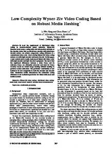
A. Transmitter Model � �T Let d = dT0 , . . . , dTK−1 be the concatenation of K T sequences dk = [dk [0], . . . , dk [M − 1]] with M elements each. Therein, dk [m] corresponds to the data symbol transmitted on the kth sub-carrier and in the mth time slot, with M being the number of time slots per block and K being the number of occupied sub-carriers in the system. In GFDM, all data symbols contained in d are modulated jointly, while in the corresponding OFDM case each dk is processed individually. The grid of resource elements of the two schemes are compared in Fig. 1, under the assumption that both operate with the same sub-carrier bandwidth and spacing. In GFDM, the transmit samples x[n] are obtained through the pulse shaping operation x[n] =
M −1 K−1 X X m=0 k=0
kn
dk [m] g˜Tx [n − mN ]ej2π N ,
(1)
where n = 0, . . . , N M − 1 is the sample index, N with N ≥ K is the number of samples per time slot, m = 0, . . . , M − 1 and k = 0, . . . , K − 1. Further, gTx [n] defines the pulse shape that is applied to the individual sub-carriers and g˜Tx [n] = gTx [(n + M N/2) mod M N )−M N/2] is a circularly shifted version as shown in Fig. 2. When all transmit samples are collected in a vector x = T [x[0], . . . , x[N M − 1]] , the GFDM transmitter can be formulated as [9] x = Ad. (2) Herein, A is a N M ×KM complex valued modulation matrix with elements based on the parameters M , K, N and gTx = T [˜ gTx [0], . . . , g˜Tx [N M − 1]] . The matrix A contains all transmit signal processing operations and is given by x=
H WN M
K−1 X
(L)
P(k) ΓTx R(L) WM dk ,
(3)
k=0
where the data symbols dk on the kth sub-carrier are first transformed to frequency domain by multiplication with an M × M discrete Fourier transform (DFT) matrix WM = ij {wi,j }M ×M , where wi,j = e−j2π M with i = 0, . . . , M − 1 and j = 0, . . . , M − 1.
GFDM OFDM
d3 [0] d3 [1] d3 [2] d3 [3] d3 [4] d2 [0] d2 [1] d2 [2] d2 [3] d2 [4] CP CP CP CP CP d1 [0] d1 [1] d1 [2] d1 [3] d1 [4] d0 [0] d0 [1] d0 [2] d0 [3] d0 [4]
Figure 1. K = 4.
amplitude
In the following we focus on the GFDM matched filter receiver, because the drawback of zero forcing is its noise enhancement property, while the linear minimum mean squared error receiver involves a computationally heavy matrix inversion. Further, root-raised cosine filters are employed in this work for pulse-shaping the sub-carriers, which means that after the matched filter is applied, the Nyquist property is met. Note that GFDM is not restricted to this pulse shape.
d3 [0] d2 [0] CP d1 [0] d0 [0]
amplitude
II. S YSTEM D ESCRIPTION
time slots d3 [1] d2 [1] d1 [1] d0 [1]
d3 [2] d2 [2] d1 [2] d0 [2]
d3 [3] d2 [3] d1 [3] d0 [3]
d3 [4] d2 [4] d1 [4] d0 [4]
sub-carriers
between non-orthogonal sub-carriers, while section IV shows computational complexity and simulation results of bit error rates. Section V provides conclusions.
Different block structures in OFDM and GFDM for M = 5 and
1
gTx [n]
0.5 0 1
g˜Tx [n]
0.5 0 0
1
2 3 normalized time n/N
4
5
Figure 2. GFDM sub-carrier filter shape g˜Tx [n] and its relation to gTx [n] for a root raised cosine pulse with α = 0.3, M = 5 and N = 4.
Then, tightly related to the localized non-zero coefficients of the frequency response of the pulse, the resulting frequency samples are duplicated L-fold by multiplication with a repetion �T matrix R(L) = IM IM . . . , which is a concatenation of L identity matrices IM of size M × M . This operation corresponds to an L times upsampling in time domain [10]. (L) Subsequently, each sub-carrier is filtered with ΓTx , a matrix (L) which contains WLM gTx on its diagonal and zeros otherwise. (L) Note that, while gTx contains N M filter coefficients, gTx can be downsampled by N/L and thus reduced to only LM samples, if it contains negligible filter coefficients that are zero and near-zero in frequency domain. Lastly, the kth sub-carrier is up-converted to its respective sub-carrier frequency with the permutation matrix P(k) , which can be constructed according to � �T ILM/2 0LM/2 · · · 0LM/2 0LM/2 P(0) = 0LM/2 0LM/2 · · · 0LM/2 ILM/2 � �T 0LM/2 ILM/2 · · · 0LM/2 0LM/2 (1) P = ILM/2 0LM/2 · · · 0LM/2 0LM/2 LM etc. with 0LM/2 being an LM 2 × 2 matrix containing zero elements. This matrix shifts and exchanges the upper and lower part of the base band spectrum of the sub-carrier onto its band pass representation.
magnitude
1
k=0
k=1
k=2
k=3
1
1.5 2 2.5 0 normalized frequency n /M
3
0.5 0 0
0.5
3.5
4
1
k=1
k=2 k=0
k=1
k=1
0.5
k=2
0
0.5 1 1.5 normalized frequency n0 /M
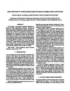
(b) Isolated sub-carrier k of interest P(k)
Figure 3.
k=0
k=2
k=0
0
�T
2
WN M y
0
0.5 1 1.5 normalized frequency n0 /M (L)
(c) After matched filter ΓRx
P(k)
�T
2
WN M y
0
0.5 n0 /M
1
(d) Decimated signal �T (L) �T R(L) ΓRx P(k) WN M y
Illustration of the signal reception process for M = 5, K = 4, L = 2, N = K, α = 0.3, where the sub-carrier of interest is k = 1.
After that, the signals of all K sub-carriers are superpositioned and the result is transformed back to the time H domain with WN M. B. Channel Model To take into account the effect of the wireless channel, the model y ¯ = Hx + v (4) � is considered. Therein v ∼ N 0, σ 2 is a vector of white Gaussian noise samples with variance σ 2 . H is a circular channel matrix that is built from an exponential power delay profile which denotes a Rayleigh multi-path channel. y ¯ is a vector containing the unequalized time samples at the receiver. Assuming that the channel matrix is known at the receiver, equalization can be performed with zero forcing according to y = H−1 y ¯. When investigating AWGN, H = I and y = y ¯. C. Receiver Description in Frequency Domain To derive a simple formulation of the receiver, in this section transmitter and receiver are considered to operate with perfect synchronization and any channel and noise disturbances are neglected, thus y = x. Based on (1), the matched filter operation for a GFDM system can be formulated as � � kn yˆ[n] = y[n]e−j2π N ~ g˜Rx [n] dˆk [m]
= yˆ[n = mN ]
(5)
where ~ denotes circular convolution with respect to n and with periodicity M N .
pass
1 magnitude
magnitude
(a) Neglecting fading and noise, the received signal in frequency domain WN M y is a superposition of K sub-carrier signals
Γ(f)
Γ(f) Γ(f)
0.5
Γ(r)
Γ(f) Γ(r)
0 0
stop 0.25 0.5 0.75 0 normalized frequency n /M
1
Figure 4. Illustration of the filter flanks in the positive part of the spectrum for α = 0.3. In frequency domain, M is the number of samples per subcarrier. The solid lines denote the useful parts of the sub-carrier signal, while the dashed lines correspond to interference.
Equivalently, the matched filter (5) can be represented for all sub-carriers jointly in matrix notation. To obtain a reconstruch iT ˆ k = dˆk [0], . . . , dˆk [M − 1] from tion of the transmit data d T
a vector of received samples y = [y[0], . . . , y[M N − 1]] , the signal processing operations of the transmitter need to be reversed. Based on (2), this is implemented using the matched version of the modulation matrix according to ˆ = AH y. d
(6)
Following the reduced-complexity frequency-domain transmitter processing from (3), we can state the matched filter for the kth sub-carrier in matrix notation as � �T � �T (L) H ˆ k = WM d R(L) ΓRx P(k) WN M y (7)
domain conversion WN M
�
frequency domain processing P
�T (k)
R(L)
�T
domain conversion ˆk d M
WH IFFT
FFT
y
downconv. NM × 1 Figure 5.
ΓRx
�
NM × 1
ˆ0 d ˆ1 d
...
filter decimation
LM × 1
LM × 1
M ×1
M ×1
Block diagram depicting GFDM receiver processing, based on frequency domain representations of the signal.
for each individual sub-carrier. By doing so a reduction in computational complexity is achieved compared to (6). �T In the above equation, P(k) has the function of a selection matrix that combines two operations. First, it rotates the frequency representation WN M y by kM samples, which corresponds to a circular down-conversion of the kth subcarrier to zero frequency. Second, it applies an ideal low-pass filter on sub-carrier k, by eliminating frequency samples in the signal that correspond to zero coefficients in the receive filter Fig. 3(b). � �∗ (L) (L) is applied according Next, the receive filter ΓRx = ΓTx to Fig. 3(c). Note that in analogy to the transmit filter, the receive filter is only represented by LM filter coefficients. This is based on the same precondition that each sub-carrier pulse shape is sparse in frequency domain and leaks only into L − 1 ≤ N neighboring sub-carriers. Narrow-band filters like raised cosine filters have frequency domain transfer functions defined in terms of its roll-off dispersion α, which ranges from very sharp non-realizable 0% up to 100% of the Nyquist bandwidth of the transmitted signal. Apart from this range, the coefficients are equal to zero for infinite-length impulse responses, but can still be considered to be near-zero for realizable filters. Subsequently, a decimation of the LM samples by factor L is necessary in order to produce the M samples that correspond to the same number of data symbols transmitted on the kth sub-carrier. In frequency domain, this can be achieved by superpositioning L chunks of M samples each (Fig. 3(d)). The decimation in frequency domain is performed �T with R(L) . Finally, the resulting signal needs to be transformed to H time domain with a M -points IFFT denoted by WM . From there, the data bits can be obtained through de-mapping of the constellation, e.g. via hard decision. A block diagram summarizing the receiver operations is depicted in Fig. 5. III. S ELF -I NTERFERENCE BETWEEN N ON -O RTHOGONAL S UB - CARRIERS Fig. 4 presents how the sub-carrier pulse shape changes throughout the filtering process. Generally, the filter shape can be characterized by three regions: A pass band where the normalized filter coefficients are one, a transition region and a
stop band where the coefficients are zero. Here, the root raised cosine transitions offer the mentioned flexibility to scale the width of the transition band. While α = 0 produces a step function, with α = 1 the flank spans over the width of one additional sub-carrier. The rising and falling flank of the filter in frequency domain shall be denoted by Γ(r) and Γ(f) , which in this case have coefficients that are taken from the square root of cosine functions on their diagonals and contain zeros otherwise. The illustrations in Fig. 4 and Fig. 3 are based on the assumption, that only adjacent sub-carriers interfere with each other. The parameter denoting the width of the sub-carrier filter in frequency domain is then chosen as L = 2. With the transition waveforms, we can follow the matched filtering process step by step. Applying the matched filter to the sub-carrier of interest requires to multiply flanks of the same kind, i.e. Γ(r) Γ(r) and Γ(f) Γ(f) , which here produces a cosine roll-off shape. However, as in the course of the receiver processing also interfering portions of the neighboring subcarriers remain, also flanks of different kinds are multiplied, i.e., Γ(f) Γ(r) . With this knowledge, it is possible to split the kth sub-carrier’s received signal into useful and interfering part. After decimation in frequency domain, as shown in Fig. 3(d), effectively left and right half of the spectrum are superpositioned, yielding � �T � �T (L) yk = R(L) ΓRx P(k) WN M y =
Γ(r) Γ(r) d0 k + Γ(f) Γ(f) d0 k + . . . {z } | signal
Γ Γ d k−1 + Γ(f) Γ(r) d0 k+1 {z } | (f)
(r) 0
interference
=
d0 k + Γ(f) Γ(r) (d0 k−1 + d0 k+1 )
(8)
in the ideal case without channel fading and noise. From d0 k , the transmitted data symbols can be obtained through inverse H 0 DFT as dk = WM d k . If uncertainties introduced to the signal by the wireless channel are to be considered, it is not always possible to separate the sub-carrier of interest from its interfering neighbors. In that case a decision rule, e.g. the H distance to the closest QAM point, is used to map WM yk to the constellation grid of the transmitted signal, which then ˆk . yields the estimates d
109
In order to explore how interference between adjacent subcarriers can be mitigated iteratively, the notation needs to be extended by an iteration index j = 1, . . . , J. The vector of received frequency-domain samples yk then corresponds to (j) ˆ k to d ˆ (j) respectively. yk and the received data symbols d k (0) (0) ˆ denotes the raw vectors (8) With this notation, yk and d k after matched filtering on which no interference cancellation (IC) has been performed. The IC algorithm can be described by the following pseudocode instructions: H (0) receive all sub-carriers as WM yk ˆ (0) map each symbol to closest QAM point to obtain d k for j = 1 to J do for k = 0 to K − 1 do remove interference by computing � � (j) (0) ˆ (j−1) ˆ (j−1) y = y −Γ(r) Γ(f) WM d +d k
k
k−1 mod K k+1 mod K H (j) update the received symbols with WM yk ˆ (j) map each symbol to closest QAM point to obtain d k
end for end for Essentially, the process consists of detecting the data symˆ (j) and using them in the j +1th iteration to compute the bols d k � � ˆ (j−1) ˆ (j−1) interfering signal Γ(r) Γ(f) WM d k−1 mod K + dk+1 mod K , (0)
which is then subtracted from the original signal yk , in order (j) to obtain a interference-reduced version of the data from yk .
complex multiplications C
A. Low Complexity Interference Cancellation
COFDM CGFDM,Tx,(3)
108
CGFDM,Tx,(2) and Rx,(6) CGFDM,Rx,(7) CGFDM,Rx,(7),J=16
107 106 105 104
2
4
6
8 10 12 14 block length M
16
18
20
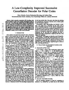
Figure 6. Comparison of the number of complex valued multiplication required to transmit/receive the signal. Uncoded transmission, synchronization and equalization are not accounted for. The parameters correspond to the LTE standard: N = 2048, K = 1201, L = 2. The block size M is varied.
and J = 16 is given in Fig. 6 and shows a nearly linear dependency on the iteration count J. Further, as a reference the modulation matrix based approach according to (2) and (6) and the DFT based transmitter (3) are presented. For the DFT based approach, without IC iterations at the receiver, the transmitter and the receiver require the same amount of multiplications.
B. Bit Error Rate Analysis Fig. 7(a) and Fig. 7(c) depict the bit error rates for unA. Complexity Analysis coded AWGN transmission with a 64QAM, while results for The computational complexity of the receiver processing in 256QAM are shown in Fig. 7(e). In the case of 64QAM, a terms of complex valued multiplications can be expressed as wide and a narrow sub-carrier filter with roll-offs α = 0.2 CGFDM,Rx,(7) = N M log2 N M + KLM + KM log2 M , where and α = 0.4 are compared. The curves with the label ”no IC” N M log2 N M originates from the N M × N M points DFT, correspond to the receiver (7) prior to interference cancellaKLM denotes for the matched filtering of the sub-carriers and tion. They show that inter-carrier interference has a significant KM log2 M originates from the inverse DFT that converts impact, as with these high modulation orders the distance the signal back to time domain. Note that it is assumed that between the constellation points is effectively reduced. all other operations can be performed as manipulations of After applying just two iterations of the presented lowregisters and summations are not counted. Applying the IC complexity IC algorithm, the initial error floor in Fig. 7(a) algorithm J times to all sub-carriers introduces an additional can be removed. However, in Fig. 7(c) and Fig. 7(e), the JKM log2 M operations for transforming the estimated data impact of the self-interference is stronger. Although there is an symbols to frequency domain, JKM for applying the interimprovement, after applying the same number of IC iterations, ference filter and another JKM log2 M for transforming back a larger gap to the theoretical curve remains. In Fig. 7(e), the to time domain. The total complexity of the frequency domain 256QAM symbol alphabet makes the hard decision strategy receiver with interference cancellation can be then found as of the IC algorithm less effective, thus an even larger number CGFDM,Rx,(7),J =N M log2 N M + KLM + KM log2 M + . . . of iterations is necessary to approach the theoretical curve. The BER behavior in a Rayleigh multipath fading enviJKM log2 M + JKM + JKM log2 M (9) ronment is presented in Fig. 7(b), Fig. 7(d) and Fig. 7(f). In As the results in [8] relied on subtracting a cancellation general, the behavior of the curves follows the characteristics signal in time domain, a significant advantage of the method of the AWGN case. In the 256QAM case it is interesting to presented in this paper is that it does not require to re- note, that unlike in the AWGN counterpart, between J = 8 and modulate the received data symbols, but allows to perform J = 16 there is no significant improvement and a gap to the the IC directly in frequency domain. A comparison of the theoretical curve remains, which again shows the limitations computational effort of the DFT based receiver (7) for J = 0 of hard decisions. IV. R ESULTS
V. C ONCLUSIONS To design a more flexible PHY for future MTC traffic, GFDM can offer burst oriented modulation with pulse-shaped sub-carriers. This approach is non-orthogonal and the benefits come at the cost of self-created inter-carrier interference, which degrades bit error rate performance. However, the effect can be mitigated, e.g., by successive interference cancellation techniques at the receiver. This work presents a low complex receiver for GFDM based wireless communication, which is able to exploit the sparse representation of the sub-carrier filter in frequency domain. This property is further utilized to simplify the interference cancellation algorithm that was proposed in [8], resulting in a smaller complexity overhead compared to OFDM than previously. Additionally, the performance of GFDM is evaluated for higher order QAM modulation, as IC becomes particularly relevant. The complexity can be further scaled towards the requirements of MTC devices by using only one sub-carrier per link in a multi-user scenario. Furhter, as the current proposal touches the issue of error propagation only in a superficial way, there is still room for improving the scheme in the future, e.g., by taking into account the reliability of the received symbols when computing the cancellation signal.
100
10−1
10−2
theory no IC J =1 J =2 J =4 J =8
10−3
10−4
0
(a) 64QAM, AWGN, α = 0.2
R EFERENCES [1] G. Fettweis, M. Krondorf, and S. Bittner, “GFDM - Generalized Frequency Division Multiplexing,” in Proc. 69th IEEE Vehicular Technology Conference, VTC Spring 2009. [2] B. Saltzberg, “Performance of an efficient parallel data transmission system,” Communication Technology, IEEE Transactions on, vol. 15, no. 6, pp. 805 –811, December 1967. [3] R. Chang, “High-speed multichannel data transmission with bandlimited orthogonal signals,,” Bell Systems Technical Journal, vol. 45, pp. 1775– 1796, December 1966. [4] M. Bellanger et al, “FBMC Physical Layer: A Primer,” June 2010. [5] B. Farhang-Boroujeny, “Ofdm versus filter bank multicarrier,” Signal Processing Magazine, IEEE, vol. 28, no. 3, pp. 92 –112, May 2011. [6] F. Schaich, “Filterbank based multi carrier transmission (fbmc) - evolving ofdm: Fbmc in the context of wimax,” in European Wireless Conference, EW 2010, April 2010. [7] T. Ihalainen, A. Viholainen, T. Stitz, and M. Renfors, “Generation of filter bank-based multicarrier waveform using partial synthesis and time domain interpolation,” Circuits and Systems I: Regular Papers, IEEE Transactions on, vol. 57, no. 7, pp. 1767 –1778, July 2010. [8] R. Datta, N. Michailow, M. Lentmaier, and G. Fettweis, “GFDM Interference Cancellation for Flexible Cognitive Radio PHY Design,” in Proc. 76th IEEE Vehicular Technology Conference, VTC Fall 2012. [9] N. Michailow, S. Krone, M. Lentmaier, and G. Fettweis, “Bit Error Rate Performance of Generalized Frequency Division Multiplexing,” in Proc. 76th IEEE Vehicular Technology Conference, VTC Fall 2012. [10] N. Michailow, I. Gaspar, S. Krone, M. Lentmaier, and G. Fettweis, “Generalized Frequency Division Multiplexing: Analysis of an Alternative Multi-Carrier Technique for Next Generation Cellular Systems,” in International Symposium on Wireless Communication Systems, ISWCS 2012.
0
10 20 Eb /N0
(b) 64QAM, Rayleigh, α = 0.2
100
10−1
10−2
theory no IC J =1 J =2 J =4 J =8
ACKNOWLEDGMENT This work has been performed in the framework of the ICT project ICT-318555 ”5GNOW”, which is partly funded by the European Union.
10 20 Eb /N0
theory no IC J =1 J =2 J =4 J =8
10−3
10−4
0
10 20 Eb /N0
(c) 64QAM, AWGN, α = 0.4
theory no IC J =1 J =2 J =4 J =8 0
10 20 Eb /N0
(d) 64QAM, Rayleigh, α = 0.4
100
10−1 theory no IC J =1 J =2 J =4 J =8 J = 16
10−2
10−3
10−4
0
10 20 Eb /N0
(e) 256QAM, AWGN, α = 0.4
theory no IC J =1 J =2 J =4 J =8 J = 16 0
10 20 Eb /N0
(f) 256QAM, Rayleigh, α = 0.4
Figure 7. Simulated bit error rates for AWGN and Rayleigh multipath channels with different roll-off factors α and for an increasing number of IC iterations J. Note that for Rayleigh channels a cyclic prefix is inserted. Its influence on Eb is not taken into account for these curves.