Low Complexity Residual Phase Tracking Algorithm for OFDM-based WLAN Systems Suvra S. Das† ,Ratnam V.Rajakumar§ , Muhammad I.Rahman† , Arpan Pal‡ , Frank H.P.Fitzek† , Ole Olsen† ,Ramjee Prasad† †
Department of Communications Technology, Aalborg University,e-mail:
[email protected] ‡ Tata Consultancy Services,§ IIT Kharagpur,India
Abstract— This paper presents the design of an efficient low complexity residual phase tracking algorithm for Orthogonal Frequency Division Multiplexing (OFDM) based Wireless Local Area Network receivers. In this paper the focus is on mitigation of the residual carrier frequency synchronization offset and sampling frequency offset. We propose a novel algorithm that uses piecewise linear approximation to estimate the complex exponential of the phase angle at pilot locations instead of estimating the actual phase angle by highly complex (costly) angle computation and search functions. This helps in reducing the implementation cost of an OFDM receiver. By means of analysis and simulation we show that our design combines both high performance and low complexity.
I. I NTRODUCTION Wireless Local Area Networks (WLAN) are becoming part of omnipresent communication infrastructures. WLANs are being applied in hotels, airports, cafes and various other locations. Different types of terminals are already (or planed to be) equipped with WLAN such as laptops, PDAs, and mobile phones. After the first phase where WLANs were penetrating the consumer market, now we are in the next phase supporting enhanced quality of services (QoS). First systems were based on direct sequence or frequency hopper spread spectrum technology. Currently Orthogonal Frequency Division Multiplexing (OFDM) is the chosen technology for enhanced and future high data rate WLAN systems. OFDM is a key technology to mitigate the multi-path effect of the wireless channel. It has been already used in DVB–T, IEEE 802.11a and 16a. It is being considered for IEEE 802.20 and IEEE 802.11n as well. OFDM will remain as the key enabling technology for achieving higher data rates in wireless packet based communication in next few years to come [1]. Targeting the mass market of wireless modules low cost solution has to be found, having in mind the tradeoff between efficiency and price. Cost of an OFDM receiver largely depends on the implementation complexity of the synchronization and channel estimation algorithms. High accuracy is needed in synchronization since coherent demodulation of OFDM is extremely sensitive to such errors. Carrier and sampling frequency acquisition and maintenance with high accuracy is vital for successful transmission of long packets. Residual Carrier Frequency Offset (CFO) and Sampling Frequency Offset (SFO) tracking (phase tracking Figure 1) are thus very critical part of OFDM receivers. But, the tracking module is highly complex [2], [3], and thus has significant potential for cost optimization of OFDM receivers. The synchronization impairments that an OFDM receiver has to mitigate are Frame Timing Offset (FTO) or Symbol Timing Offset (STO), taken care of in the Time Synch, CFO compensated by the Frequency Synch block of Figure 1. Such algorithms are very well discussed in several literatures [4], [5] and many more. In this article, we deal with the residual CFO and SFO errors, jointly termed as Residual Phase Errors. Residual Phase Error is the combined error due to non-exact carrier frequency offset correction and existing sampling frequency offset. In a real environment the synchronization
LNA
Low Pass Filter
X
ADC converter
Frequency Synch
Time Synch
Low Noise Amplifier Local Oscillator
Phase Tracking
Channel Equalization
Front End(Inner Receiver) Back End (OuterReceiver)
Fig. 1.
FFT Fast Fourier Transform
De-Mapper
Channel Decoder
Bit(s) output
OFDM receiver front end architecture
blocks placed at the receiver front end are not able to estimate the exact carrier frequency offset due to circuitry noise and fixed word length effects. Moreover due to sampling frequency offset there is a slowly increasing timing offset. The receiver has to continuously track and compensate for these effects in order to improve the efficiency of the system. Literatures describing correction algorithms use the search function argmax [2], [3], [6], [7] after complex– conjugate–multipy–add operations. They also need to compute the inverse tangent [3], [5], [8], [9], [10] to find the phase angles. The implementation complexity is very high for all these necessary function blocks [3]. In this paper we propose a novel algorithm for residual phase tracking without using either of the afore mentioned complex (costly) arithmetic functions. It computes the complex exponential of the phase angle at the pilot-tone locations instead of the phase angles to minimize the implementation complexity. The design of our algorithm is such that it can be very easily applied to any coherent OFDM demodulation scheme for WLAN type of networks. The remainder of the article is organized as follows. In Section II we describe the system under investigation. Then we briefly present the well known mathematical analysis describing residual synchronization errors in OFDM systems. Our proposed novel algorithm is described in Section IV. A detailed discussion on the performance evaluation of our scheme is given in section V. II. S YSTEM U NDER I NVESTIGATION A. Frame Format OFDM systems vary greatly in their implementation. It is thus important that we describe the frame format referred in this article. We consider the IEEE802.11a [11] frame format as described in Figure 2. A transmitted packet has an all pilot (known data at Transmitter (Tx) and Receiver (Rx)) training sequence known as PREAMBLE at its beginning. It is used for packet start identification, automatic gain control system, symbol timing synchronization, initial carrier frequency synchronization and channel estimation. A Guard Interval (GI) follows the PREAMBLE which in turn is followed by the SIGNAL field. The SIGNAL field has information about the packet length and modulation format used in the frame. It is a Binary Phase
G I
PREAMBLE
S U B C A R R I E R S
SIGNAL
G I
DATA
N-1
G I
G I
DATA
Time
where n(t) is additive white gaussian noise. Here, Hk is the channel transfer function (CTF) for kth subcarrier. III. R ESIDUAL P HASE E RROR IN THE R ECEIVER
Pilots (Amplitde +/-1)
Residual Phase Error has already been defined in Section I. FTO and CFO corrected signal after FFT can be expressed from [2], [5]
Zero (Amplitude 0 )
2π
Data Sub-carrier
Rl,k = Hk Xl,k ej N (NCP +lNsym )φk ej(π
Nd −1 φk +θ) N
sin(πφk ) “ ”
sin + Nl,k
0
Fig. 2.
OFDM frame format
Shift Keying (BKSP) modulated OFDM symbol. Then follows a sequence of DATA fields separated by GIs, i.e the OFDM symbols carrying information. There are 64 subcarriers used in the Fast Fourier Transform (FFT) block of the OFDM system under consideration. Not all subcarriers are used to carry information. Some subcarriers such as the zero frequency component (to avoid carrier transmission) and the higher frequency subcarriers are made zero in order to avoid the filtering effect on the subcarriers due to analogue components. Hence only 52 subcarriers carry non-zero power, among which, pilots tones (values ±1) are present at four distinct locations (subcarriers -21,-7,7 and 21). Thus only 48 subcarriers carry data information.
1 sl (t) = √ Td
N/2−1
X
0
Rl,k = Xl,k Hk ejlφk C + Nl,k
2π k t−lT jT [ sym −TCP ]
Xl,k e
d
(1)
k=−N/2
Where Xl,k are constellation points to IDFT input at kth subcarrier of lth OFDM symbol; Tsym , Td , TCP and Ts are duration of complete OFDM symbol, data part, Cyclic Prefix (CP or GI) and sampling period respectively. Similarly, Nsym , Nd , NCP defines samples for complete OFDM symbol, data part and CP respectively. Tsym = Td + TCP , Nsym = Nd + NCP and N = Nd . Further on we shall omit the scaling factor for simplification of representation. The signal in Equation 1 is transmitted over frequency–selective fading channel, which is characterized by its low–pass–equivalent impulse response h(τ, t) plus AWGN n(t). The channel is considered to be quasi–static during the transmission of a complete packet, thus h(τ, t) simplifies to h(τ ) [5]. It is further assumed that the effect of channel response h(τ ) is restricted to the interval t ∈ [0, TCP ], in another words, the length of CP is chosen to be longer than the maximum possible delay spread, τmax . In this way the guard interval (the cyclic prefix) is able to completely absorb the tail of the pulse of the previous symbol. Received baseband signal at the receiver antenna can be written from [5] τZ max
sl (t − τ )h(τ )dτ
r(t) =
(2)
0 N/2−1
=
X k=−N/2
2π k t−lT jT [ sym −TCP ]
Hk Xl,k e
d
(4)
Where φk ≈ kζ + ξTd ; θ the carrier phase offset; ξ = δ(Frx − Ftx ); Ftx and Frx are the local oscillator frequencies at the transmitter and the receiver respectively and δ implies residual error after initial carrier frequency offset correction. ζ is the receiver sampling frequency 0 0 offset defined through Ts = Ts (1 + ζ); where Ts is the receiver sampling period and Ts the transmitter sampling period. Residual carrier frequency offset in the signal even after CFO correction together with the sampling frequency offset cause phase rotation in each subcarrier to increase with OFDM symbol index l as can be seen from Equation 4. Cumulative phase increment severely limits the number of OFDM symbols that can be transmitted in one packet. The receiver thus has to continuously track and compensate for the effect (Phase Tracking block of Figure 1). Since the time invariant terms are inseparable from the channel transfer function, we can write
B. OFDM Transmission Signal Model An OFDM symbol consists of a sum of subcarriers that are modulated by using any linear modulation method, such as Binary Phase Shift Keying (BPSK) or Quadrature Amplitude Modulation (QAM). The transmitted baseband signal for lth OFDM symbol, sl (t) can be expressed as [2]:
+ n(t)
(3)
πφk Nd
0
2π
where Hk = Hk ej N NCP φk ej(π
Nd −1 φk +θ) N
(5)
sin(πφk ) “ πφ ” sin N k d
N
and C = 2π sym . N 0 2 = So, we can call Hk as the equivalent channel transfer function. σN 2 E{|Nl,k | } is the additive noise power [2], where E{...} denotes expected value. There is an ICI term present in the received signal which can be represented as additional noise term. This leads to degradation in the available SNR. The power of the ICI term of the kth sub-carrier of the lth OFDM symbol is given by [6] π2 (kζ)2 (6) 3 In OFDM-WLAN environment of 64 sub-carriers OFDM symbol, 2 this effect is very small at values of ζ ∼ 10−5 and thus σl,k−ICI can be omitted now for the algorithm under discussion. We need to mention here that if the slowly increasing sampling timing drift due to SFO reaches one sampling period, then we either miss a sample or oversample it. This leads to irreducible ISI. Rob-stuff [12] method is used to combat such an effect. This particular situation is not addressed by our algorithm. 2 σl,k−ICI ≈
IV. O FFSET C ORRECTION A LGORITHM In this section we elaborate on the proposed residual phase correction algorithm. First, after channel equalization the estimate of the exponential part (ejlφk C ) of Equation 5 is computed at the pilot locations, instead of estimating the phase (lφk C). Then a running time-averaging is done to increase the SNR of the estimates. Finally using the estimates at pilot locations we piece-wise-linearlyinterpolate (Figure 3) the compensating complex exponential at all the data subcarriers. These are then multiplied with Rl,k after channel equalization. The effect of noise in the channel estimate can be reduced to as low as 0.41dB by using a channel estimator Gain of 10dB [2]. Thus for now we assume ideal channel compensation. If the estimated
Piece–wise–linear–interpolation is done to find the complex multiplication factor for each subcarrier for compensating residual phase error as states below. yl,k = βbl,p − ml (p − k)
(13) th
Where m indicates the nearest pilot index to k subcarrier. The for 00 0 ∗ compensation we use Rl,k = Rl,k · yl,k . The maximum errors that may occur will be at the farthest subcarriers where the difference is largest because of larger sub-carrier index (see Equation 4 & 5). V. P ERFORMANCE OF A LGORITHM In [13] received signal after compensation by the proposed algorithm for small angles is given by Fig. 3.
00
Rl,k = Xl,k + Xl,k {lB(p − k)}2
Piece wise linear interpolation
≈ Xl,k 0
b k we assume H b k ≈ Hk . It is to be channel transfer function is H noted for IEEE 802.11a type wireless networks a basic assumption is that the channel quasi–static in the whole packet duration. The Long Training Sequence [11] present in the PREAMBLE is used to estimate the channel once every packet. This estimate is valid for equalizing all OFDM symbols in entire packet since channel variability is much slower than the packet duration. We can write the received subcarriers after FTO, initial CFO correction and channel compensation as 0
0
00
b k = Xl,k (αl,k )l + Nl,k Rl,k = Rl,k Hk /H
(7)
0
where Rl,k is the received subcarrier after timing, frequency and 00 channel compensation and Nl,k as the new noise term; αl,k = ejφk C jlφk C and we define βl,k = e . If Pl,p (values ±1) is the pilot tone at pth subcarrier index of the lth OFDM symbol. For all further computation we have p at pilot indexes only. The algorithm is stated as 0
0
∗ α bl,p = ν α bl−1,p + (1 − ν)Rl,p · Rl−1,p
(8)
α bl,p = α bl,p /|b αl,p | 0 ∗ b b βl,p = ν βl−1,p α bl,p + (1 − ν)Rl,p · Pl,p βbl,p = βbl,p /|βbl,p |
(9) (10) (11)
with initial conditions α b0,p = βb0,p = 1 where x b indicates estimate of x; x∗ denotes complex conjugate of x; ν is the memory factor used for averaging. Equation 8 estimates the increment from (l−1)th OFDM symbol to lth OFDM symbol. It updates previous estimates. Equation 10 estimates the compensating complex exponential for the lth OFDM symbol. Equation 8 and 10 uses averaging to increase the SNR of the estimate. A detailed derivation and analysis of the algorithm is given in [13]. It has to be noted that we are not computing the phase angle, rather the complex exponential of the phase angle. Then we interpolate the real and imaginary parts separately. The straight solid line in Figure 3 is the actual phase that needs to be estimate, and the curve is the sinusoid of the phase. We are estimating this sinusoid at the pilot locations. There will be a sine and a cosine term, only one component is shown to reduce the complexity of the figure. We approximate them to be piece–wise–linear for small angles. Then the mean slope of each of them is estimated as given below in Equation 12. Note that we are estimating the slope as a complex entity in one single equation since the real and imaginary parts do not interact in the equation stated below. ml =
βbl,p7 − βbl,p−21 1 βbl,p21 − βbl,p−7 ( + ) 2 21 − (−7) 7 − (−21)
(12)
(14)
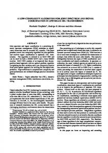
where B = ζC. Since ζ is in the order of 10−5 the degradation due to the approximation used in the proposed algorithm described in section IV is almost negligible. The noise power, for small angles, has been shown in [13] to be almost equal to the noise power present in the system before applying the algorithm. If Eb is the energy per bit and No /2 the noise power density and since for BPSK, symbol energy and bit energy are the same we can say thatq the probability of b error for BPSK modulation is given by Pe = Q{ 2E } [14] does No not degrade significantly for low residual phase errors. This is, can be understood in the light of Equation 14. A. Simulation Parameters Simulations were performed with parameters from IEEE 802.11a WLAN standard: N = Nd = 64, NCP = 16 , BPSK modulation with 1/2 code rate convolution code, but constraint length was kept as 3; Carrier frequency = 5.4 GHz; Sampling Frequency Offset = 50 ppm. We have taken the largest SFO as per the standard’s requirement since, very small SFO does not have significant effect on the performance of the receiver. Residual carrier frequency error after CFO correction was varied from ∼ 30Hz to ∼ 4kHz to test the algorithm’s performance for small ( 800bits) and larger (4000bits) packet lengths. B. Performance Comparison For comparison in correspondence to our objective, an algorithm that estimates phases angles lφk C at the pilot locations using inverse tangent function is taken with reference to [3], [8]. A linear interpolation of the phase is done for all data sub-carriers. The compensation is \ done by multiplying the received signal of Equation 5 by e−j lφk C , [ where lφ k C is the estimated phase angle. In Figure 4 and 5, we denote our algorithm as alg-1 (dotted line) and the algorithm used as reference for comparison as alg-2 (solid line). A reference Bit Error Rate (BER) level of 10−5 was chosen from IEEE802.11a [11] standard for performance comparison . 1) Low Residual Phase Error: Figure 4 shows the BER vs SNR curve for both algorithms for low residual phase error. It can be observed that both algorithms perform very closely for residual carrier frequency error in the range of ∼ 30Hz (0.005ppm) to ∼ 300Hz (0.05ppm) with sampling frequency offset of 50 ppm for both small and medium sized packet of length 800 and 4000 bits. BER of ∼ 10−5 is achieved by both algorithms at almost same SNR of about (7dB). This confirms our analysis for small angles as stated in the beginning of section V. It may be noted that the estimation of the phase angle by angle functions is not perfect because of corruption
BER Vs SNR for low Cfo 0.1 0.01
BER
0.001 0.0001 1e-05 1e-06 1e-07 1
2
3
4 SNR
alg 1 800bits 0.005Cfo alg 1 800bits 0.05Cfo alg 2 800bits 0.005Cfo alg 2 800bits 0.05Cfo
Fig. 4.
5
6
7
alg 1 4000bits 0.005Cfo alg 1 4000bits 0.05Cfo alg 2 4000bits 0.005Cfo alg 2 4000bits 0.05Cfo
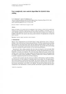
BER Vs SNR for low residual phase BER Vs SNR for high Cfo
1 0.1
BER
0.01
for OFDM based WLAN receivers to replace the complex (costly) inverse tangent and argmax function implementation. It has been observed that for low residual phase errors the proposed algorithm performs almost identical to the algorithm using phase angle estimation by inverse tangent functions. For higher residual phase errors the proposed algorithm’s performance is still stable when the other scheme almost fails. By being robust to larger residual errors it reduces stringent performance requirement of the Freq Synch block. This creates provision for lower performance requirement of the initial freq synch block followed by our tracking algorithm as given in Figure 1. Higher accuracy performance requirements of the Freq Synch block increases complexity [3] and implementation cost of the receiver. Further, our algorithm does not use the argmax or inverse tangent functions which are very costly in terms of hardware implementation. It may be mentioned here that low complexity implementation of inverse tangent function may be done using table lookup or cordic structure. With increased required resolution, table look up uses more space and cordic suffers from higher latency. In contrast, our algorithm does not have such limitations. We have thus seen for WLAN type of packet based wireless network using OFDM scheme the proposed algorithm for residual phase tracking can prove highly effective in reducing cost of receivers without compromising on performance. R EFERENCES
0.001 0.0001 1e-05 1e-06 1e-07 0
2
alg 1 alg 1 alg 2 alg 2
4
6 SNR
800bits 0.4Cfo 800bits 0.8Cfo 800bits 0.4Cfo 800bits 0.8Cfo
Fig. 5.
8
10
12
alg 1 4000bits 0.05Cfo alg 1 4000bits 0.07Cfo alg 2 4000bits 0.05Cfo alg 2 4000bits 0.07Cfo
BER Vs SNR for high residual phase
of the complex number by noise. At low angles this does not cause much deviation though. 2) High Residual Phase Error: Figure 5 shows graphs of BER vs SNR for both algorithms from simulation results for comparatively higher residual phase errors. Residual carrier frequency offset in the range of ∼ 300Hz (0.05ppm) to ∼ 4kHz (0.8ppm), sampling frequency offset of 50pmm for packet lengths of 800bits and 4000bits were considered. For 800bits packet length, residual carrier frequency offset of ∼ 2kHz (0.4ppm) alg-2 requires only about 2dB more SNR in comparison to alg-1 to meet the required performance level. But for residual carrier frequency offset of ∼ 4kHz (0.8ppm) for same previous packet length of 800bits alg-2 does not meet the required BER, where as algo-1 does meet the requirement. For larger packet length of 4000bits it can be seen that at residual carrier frequency offset of ∼ 300Hz (0.05ppm) alg-2 requires about 4dB more SNR to reach the BER of 10−5 as compared to alg-1. For larger residual carrier frequencies ∼ 400Hz (0.07ppm) alg-2 never reaches the desired performance criteria stated above, whereas alg-1 does so without significant change in SNR requirement. VI. C ONCLUSION We have presented an efficient low complexity residual phase correction algorithm, using piece-wise-linear approximation technique,
[1] Richard Van Nee & Ramjee Prasad, OFDM for Wireless Multimedia Communications. Artech House Publishers, 2000. [2] M. Speth, S.A. Fechtel, G. Fock & H. Meyr, “Optimum Receiver Design for Wireless Broad-Band Systems Using OFDM - Part I,” IEEE Transactions on Communications, vol. 47, no. 11, November 1999. [3] ——, “Optimum Receiver Design for Wireless Broad-Band Systems Using OFDM - Part II: A case study,” IEEE Transactions on Communications, vol. 49, no. 4, April 2001. [4] A. Dey, R.V. Rajakumar, S S Das, A. Pal, Balamurali., “Synchronization Algorithms For The IEEE 802.11 a/g Wireless Lan,http://kom.auc.dk/∼ssd/reports/ ,” 10th National Conference on Communications, Indian Institute of Science, Bangalore, Jan 30 - Feb 1 2004. [5] Klaus Witrisal, “OFDM Air Interface Design for Multimedia Communications,” Ph.D. dissertation, Delft University of Technology, The Netherlands, April 2002. [6] B. Yang, K.B. Letaief, R.S. Cheng & Z. Cao,, “Timing Recovery for OFDM Transmission,” IEEE Journal ON Selected Araes in Communications, vol. 18, no. 11, November 2000. [7] Baoguo Yang; Zhengxin Ma; Zhigang Cao, “ML-oriented DA sampling clock synchronization for OFDM systems,” WCC - ICCT 2000, vol. 1, pp. 781 – 784, 21-25 Aug 2000. [8] Juha Heiskala & John Terry, OFDM Wireless LANs: A Theoritical and Practical Guide, 2nd ed. Sams Publishing, July 2001. [9] I. Abhayawardhana, V.S.; Wassell, “Residual frequency offset correction for coherently modulated ofdm systems in wireless communication,” in Vehicular Technology Conference, vol. 2, VTC Spring 2002 2002, pp. 777–781. [10] Miaoudakis;et.al, “An all-digital feed-forward CFO cancellation scheme for HIPERLAN/2 in multipath environment,” in The 13th IEEE International Symposium on Personal, Indoor and Mobile Radio Communications, 2002, 4, Ed., Sept 2002, pp. 15–18. [11] IEEE Std 802.11a-1999, “Part 11: Wireless LAN Medium Access Control (MAC) and Physical Layer (PHY) specifications High-speed Physical Layer in the 5 GHz Band,” IEEE, Tech. Rep., 1999. [12] P. M. M. Pollet, T.; Spruyt, “The ber performance of ofdm systems using non-synchronized sampling,” in GLOBECOM ’94, vol. 1. IEEE, 28 Nov.-2 Dec. 1994 1994, pp. 253 – 257. [13] S.S.Das et. al, “Design of Low-Complexity OFDM-WLAN Systems Part I, http://kom.auc.dk/∼ssd/reports/,” Aalborg University, Department of Communication Techonology , Technical Report R-04-1004, ISSN 0908-1224, ISBN 87-90834-45-3, February 2004. [14] J.G.Proakis, Digital Communications, 3rd ed. Mc Graw Hill, 1995.